Downloaded 53 times


![Recursion in specifications Operations are often specified recursively Tail (Cons (L, v)) = if L = Create then Create else Cons (Tail (L), v) Cons ([5, 7], 9) = [5, 7, 9] Tail ([5, 7, 9]) = Tail (Cons ( [5, 7], 9)) = Cons (Tail ([5, 7]), 9) = Cons (Tail (Cons ([5], 7)), 9) = Cons (Cons (Tail ([5]), 7), 9) = Cons (Cons (Tail (Cons ([], 5)), 7), 9) = Cons (Cons ([Create], 7), 9) = Cons ([7], 9) = [7, 9]](https://image.slidesharecdn.com/sech910-120011444146910-5/85/SECh910-13-320.jpg)


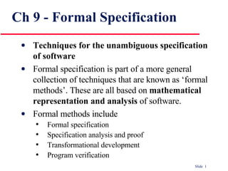
The document discusses formal specification techniques for software development. It covers formal specification as part of formal methods, which use mathematical representation and analysis. It also discusses different formal specification techniques like algebraic approaches, model-based approaches, and interface specification. While formal methods have limitations and challenges, they can be useful for safety-critical applications by reducing errors and rework.