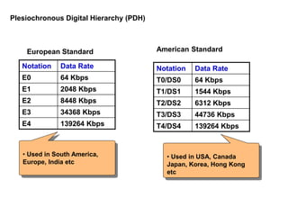
Plesiochronous Digital Hierarchy(PDH)
Notation Data Rate
E0 64 Kbps
E1 2048 Kbps
E2 8448 Kbps
E3 34368 Kbps
E4 139264 Kbps
Notation Data Rate
T0/DS0 64 Kbps
T1/DS1 1544 Kbps
T2/DS2 6312 Kbps
T3/DS3 44736 Kbps
T4/DS4 139264 Kbps
European Standard American Standard
• Used in South America,
Europe, India etc
• Used in USA, Canada
Japan, Korea, Hong Kong
etc
4.
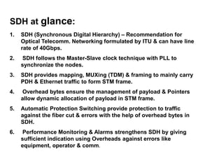
1. SDH (SynchronousDigital Hierarchy) – Recommendation for
Optical Telecomm. Networking formulated by ITU & can have line
rate of 40Gbps.
2. SDH follows the Master-Slave clock technique with PLL to
synchronize the nodes.
3. SDH provides mapping, MUXing (TDM) & framing to mainly carry
PDH & Ethernet traffic to form STM frame.
4. Overhead bytes ensure the management of payload & Pointers
allow dynamic allocation of payload in STM frame.
5. Automatic Protection Switching provide protection to traffic
against the fiber cut & errors with the help of overhead bytes in
SDH.
6. Performance Monitoring & Alarms strengthens SDH by giving
sufficient indication using Overheads against errors like
equipment, operator & comm.
SDH at glance:
5.
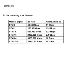
The hierarchyis as follows:
Optical Signal Bit Rate Abbreviated as
STM-0 51.84 Mbps 51 Mbps
STM-1 155.52 Mbps 155 Mbps
STM- 4 622.080 Mbps 622 Mbps
STM-16 2488.320 Mbps 2.4 Gbps
STM-64 9953.280 Mbps 10 Gbps
STM-256 39813.12 Mbps 40 Gbps
Standards
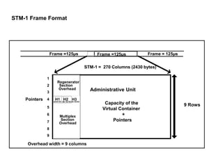
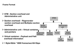
Frame Format
STM- Section overhead and
Administrative unit
Section overhead – Regenerator
section overhead and Multiplex section
overhead
Administrative unit – Virtual container
and pointers
Virtual container - Payload and Path
overhead information
1 Byte=8bits * 8000 frames/sec=64 Kbps
Payload
STM-N
Administrative
unit
Pointer
Virtual
Container
Path
overhead
Section
Overhead
Regenerator
Overhead
Multiplex
overhead
11.
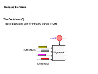
The Container (C)
–Basic packaging unit for tributary signals (PDH)
Mapping Elements
12.
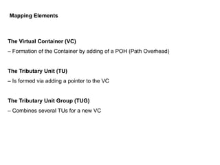
The Virtual Container(VC)
– Formation of the Container by adding of a POH (Path Overhead)
The Tributary Unit (TU)
– Is formed via adding a pointer to the VC
The Tributary Unit Group (TUG)
– Combines several TUs for a new VC
Mapping Elements
13.
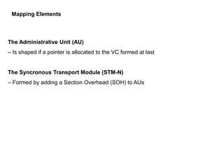
The Administrative Unit(AU)
– Is shaped if a pointer is allocated to the VC formed at last
The Syncronous Transport Module (STM-N)
– Formed by adding a Section Overhead (SOH) to AUs
Mapping Elements
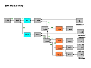
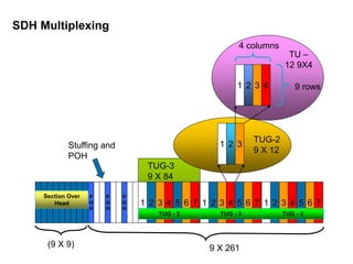
SDH Multiplexing
9 X261
7
4
3 6
5
2
1 7
4
3 6
5
2
1 7
4
3 6
5
2
1
3
2
1
4
3
2
1 9 rows
4 columns
TUG-2
9 X 12
TU –
12 9X4
TUG-3
9 X 84
P
O
H
P
O
H
P
O
H
Stuffing and
POH
TUG - 3
TUG - 3
TUG - 3
Section Over
Head
(9 X 9)
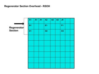
Regenerator Section Overhead- RSOH
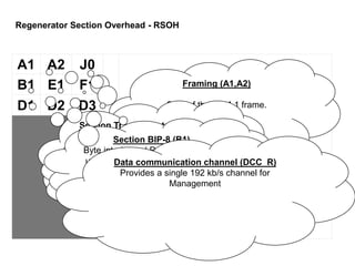
A1 A2 J0
B1 E1 F1
D1 D2 D3
Framing (A1,A2)
Start of the STM-1 frame.
Section Trace or Future Growth
(J0)
J0 carries section trace message.
Local Orderwire (E1)
Channel for voice communications
between any two NEs.
Section User Channel (F1)
A 64kb/s user channel.
Section BIP-8 (B1)
Byte interleaved Parity-8 (BIP-8) is
used for regenerator section error
monitoring.
Data communication channel (DCC_R)
Provides a single 192 kb/s channel for
Management
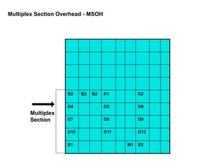
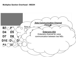
B2 K1 K2
D4D5 D6
D7 D8 D9
D10 D11 D12
S1 M1 E2
Line BIP-24 (B2)
Byte interleaved Parity-24 (BIP-
24) is used for multiplex section
error monitoring.
Multiplex Section Overhead - MSOH
Data Communication Channel
(DCC-M)
Provides a single 576 kb/s channel
for Management
Automatic Protection Switch
(APS) (K1,K2)
Used for APS signaling
Synchronization status or Future
growth (S1)
5-8 bits of the byte defines
Synchronous status message
Line Remote Error Indicator (M1)
Remote error indication. Conveys the
BIP-24 error count back to the source
Orderwire (E2)
Orderwire channel for voice
communication between two NEs
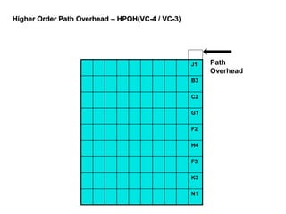
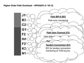
J1
B3
C2
G1
F2
H4
F3
K3
N1
Path Signal Label(C2)
Indicates the type of payload in
AU
Path Trace (J1)
J1 byte carries the trace
information at path level
Path BIP-8 (B3)
Path error monitoring
Path Status (G1)
Provides status and
performance information back
to the remote end
Indicator byte (H4)
Carries multiframe information
Path User Channel (F2)
User data channel at path level
Path User Channel (F3)
User data channel at path level
Bits 1-4 are allocated for APS.
Bits 5-8 are for future use.
Tandem Connection (N1)
IEC for tandem connection
monitoring at TCM source.
Higher Order Path Overhead – HPOH(VC-4 / VC-3)
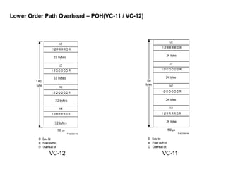
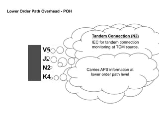
Lower Order PathOverhead - POH
V5
J2
N2
K4
Signal Label and parity check
Path Trace (J2)
J2 byte carries the trace
information at lower order path
level
Tandem Connection (N2)
IEC for tandem connection
monitoring at TCM source.
Carries APS information at
lower order path level