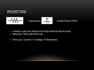
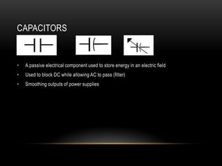
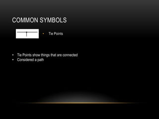
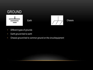
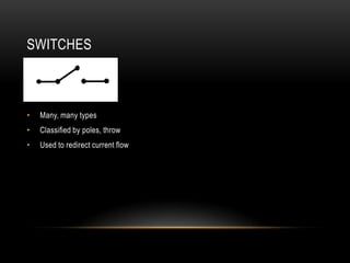
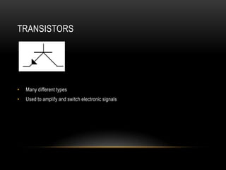
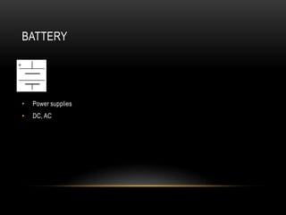
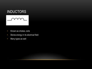
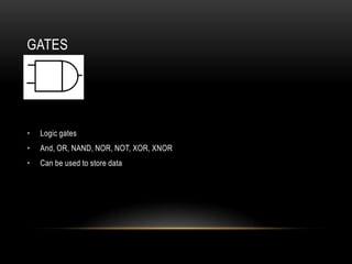
SCHEMATICS
Basic Electronics Refresher
            By
    Chris Franckowiak
WHAT ARE SCHEMATICS?


A schematic is a structural or procedural diagram, especially of an electrical or
mechanical system.


schematic. (n.d.) The American Heritage® Dictionary of the English Language,
Fourth Edition. (2003). Retrieved June 25 2012 from
http://www.thefreedictionary.com/schematic
SCHEMATICS
•   Used to graphically represent what a circuit is doing and how it is functioning.
•   An atlas or roadmap of an electrical circuit
COMMON SYMBOLS
•   The following slides look at some of the most common symbols found in electrical
    schematics
•   Not all-inclusive – many others used
RESISTORS

                    •    Fixed Resistor                  •   Variable Resistor (Pods)


 • A resistor is part of an electrical circuit that resists the flow of current
 • Measured in Ohms after Ohms Law

 • Ohms Law: I (current) = V (Voltage) / R (Resistance)
INDUCTORS
                  •    Air Core Inductor                     •   Variable Inductor


• A passive electrical component that stores energy in its magnetic field
• Also known as coils and chokes
• Used in analog circuits and signal processing
CAPACITORS


•   A passive electrical component used to store energy in an electric field
•   Used to block DC while allowing AC to pass (filter)
•   Smoothing outputs of power supplies
DIODES

                         General                                           Gunn


•   Many types (Zener, Avalanche, Gunn, IMPATT)
•   Low resistance to current flow in one direction and high (indefinite) resistance in the other
    direction
•   Used in rectifiers
COMMON SYMBOLS
                    •   Tie Points


• Tie Points show things that are connected
• Considered a path
GROUND

                        Earth                                       Chassis


•   Different types of grounds
•   Earth ground tied to earth
•   Chassis ground tied to common ground on the circuit/equipment
CONDUCTORS


•   Tie Points and overlapping lines
•   How current reaches individual components (resistors, capacitors, etc..)
SWITCHES


•   Many, many types
•   Classified by poles, throw
•   Used to redirect current flow
TRANSISTORS


•   Many different types
•   Used to amplify and switch electronic signals
BATTERY


•   Power supplies
•   DC, AC
INDUCTORS


•   Known as chokes, coils
•   Stores energy in its electrical field
•   Many types as well
GATES


•   Logic gates
•   And, OR, NAND, NOR, NOT, XOR, XNOR
•   Can be used to store data
CONCLUSION
•   Symbols represent how the circuit functions
•   Many slides could be made for each component (this is just a review of what you will see)
•   By knowing what each one is and how they work – schematics become very familiar
•   It is a learning process
Schematic powerpoint

Schematic powerpoint

  • 1.
  • 2.
    WHAT ARE SCHEMATICS? Aschematic is a structural or procedural diagram, especially of an electrical or mechanical system. schematic. (n.d.) The American Heritage® Dictionary of the English Language, Fourth Edition. (2003). Retrieved June 25 2012 from http://www.thefreedictionary.com/schematic
  • 3.
    SCHEMATICS • Used to graphically represent what a circuit is doing and how it is functioning. • An atlas or roadmap of an electrical circuit
  • 4.
    COMMON SYMBOLS • The following slides look at some of the most common symbols found in electrical schematics • Not all-inclusive – many others used
  • 5.
    RESISTORS • Fixed Resistor • Variable Resistor (Pods) • A resistor is part of an electrical circuit that resists the flow of current • Measured in Ohms after Ohms Law • Ohms Law: I (current) = V (Voltage) / R (Resistance)
  • 6.
    INDUCTORS • Air Core Inductor • Variable Inductor • A passive electrical component that stores energy in its magnetic field • Also known as coils and chokes • Used in analog circuits and signal processing
  • 7.
    CAPACITORS • A passive electrical component used to store energy in an electric field • Used to block DC while allowing AC to pass (filter) • Smoothing outputs of power supplies
  • 8.
    DIODES General Gunn • Many types (Zener, Avalanche, Gunn, IMPATT) • Low resistance to current flow in one direction and high (indefinite) resistance in the other direction • Used in rectifiers
  • 9.
    COMMON SYMBOLS • Tie Points • Tie Points show things that are connected • Considered a path
  • 10.
    GROUND Earth Chassis • Different types of grounds • Earth ground tied to earth • Chassis ground tied to common ground on the circuit/equipment
  • 11.
    CONDUCTORS • Tie Points and overlapping lines • How current reaches individual components (resistors, capacitors, etc..)
  • 12.
    SWITCHES • Many, many types • Classified by poles, throw • Used to redirect current flow
  • 13.
    TRANSISTORS • Many different types • Used to amplify and switch electronic signals
  • 14.
    BATTERY • Power supplies • DC, AC
  • 15.
    INDUCTORS • Known as chokes, coils • Stores energy in its electrical field • Many types as well
  • 16.
    GATES • Logic gates • And, OR, NAND, NOR, NOT, XOR, XNOR • Can be used to store data
  • 17.
    CONCLUSION • Symbols represent how the circuit functions • Many slides could be made for each component (this is just a review of what you will see) • By knowing what each one is and how they work – schematics become very familiar • It is a learning process