Downloaded 360 times


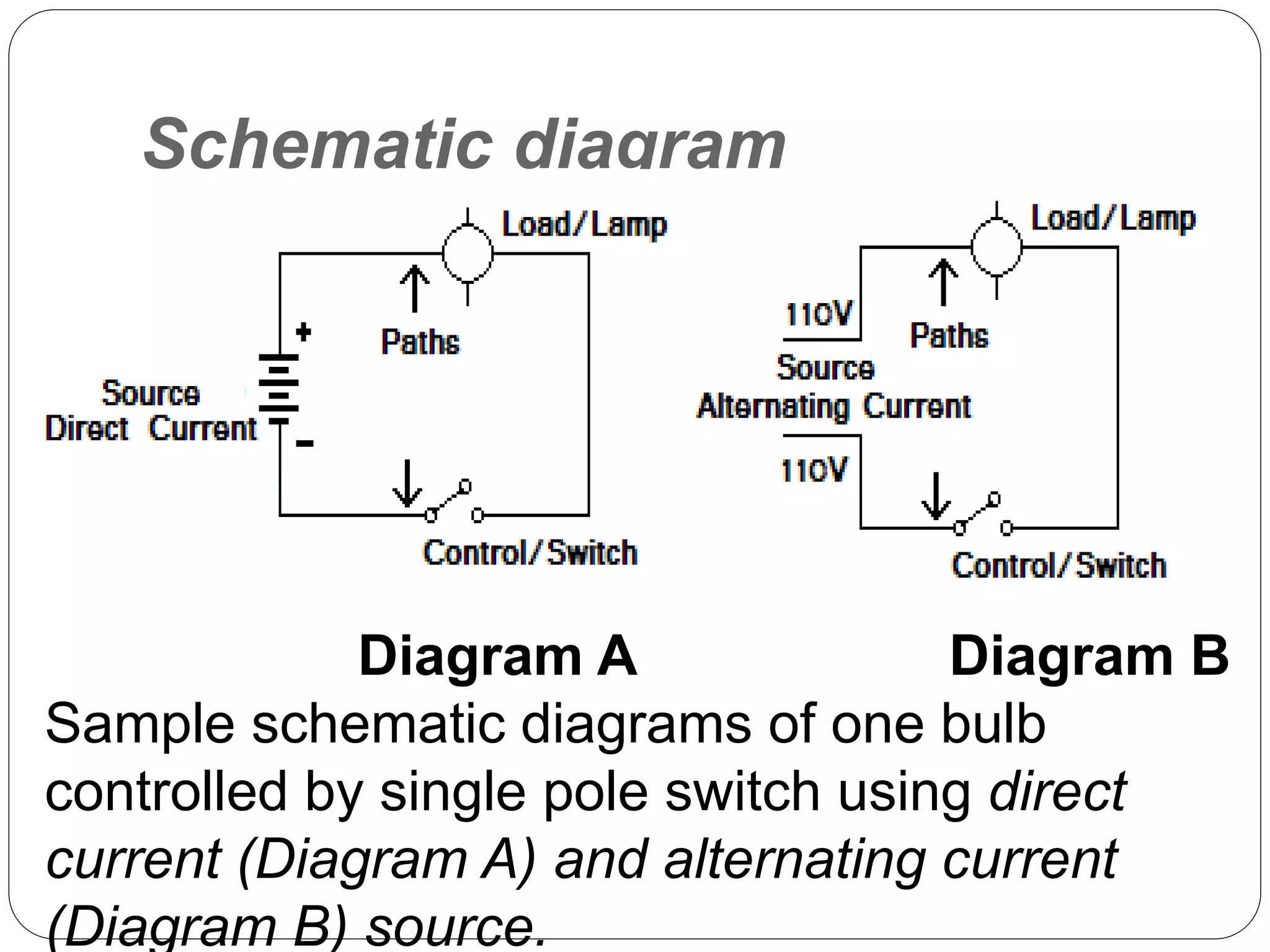


This document provides information about electrical wiring diagrams and circuits. It defines two types of diagrams - pictorial diagrams, which show the physical appearance of circuit components, and schematic diagrams, which use standard symbols to show how components are connected regardless of physical placement. It also describes two basic circuit types - series circuits where components are connected end to end and parallel circuits where components are wired across the lines. Finally, it defines an electrical plan as a graphical layout of wiring connections for a building.


