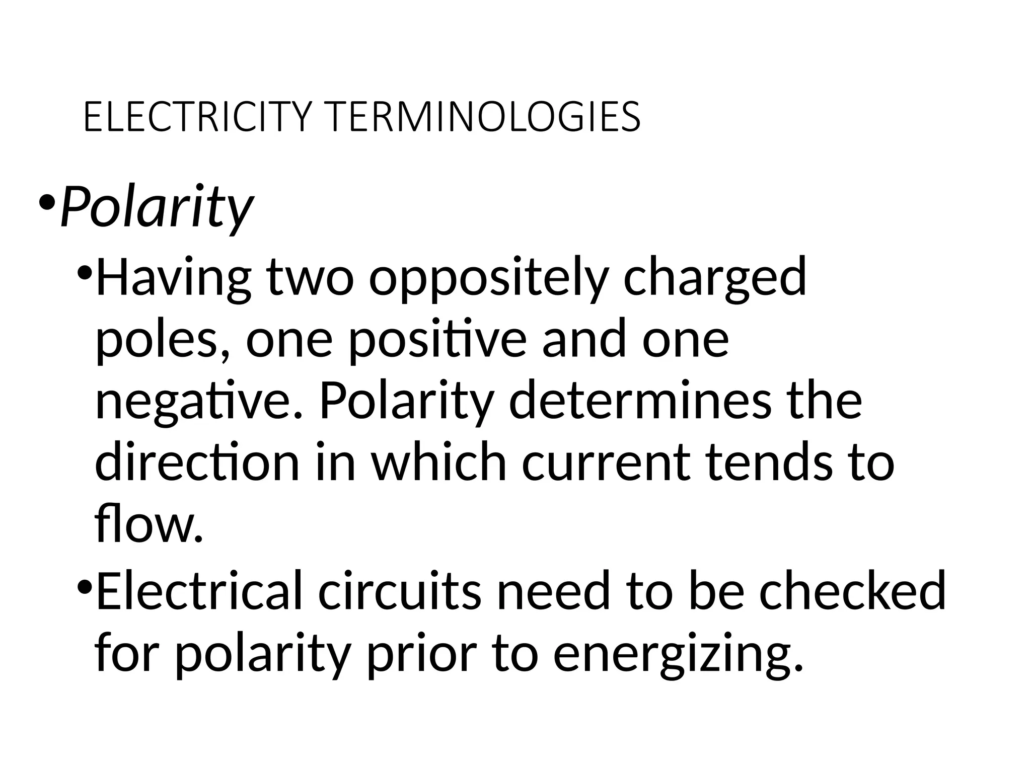
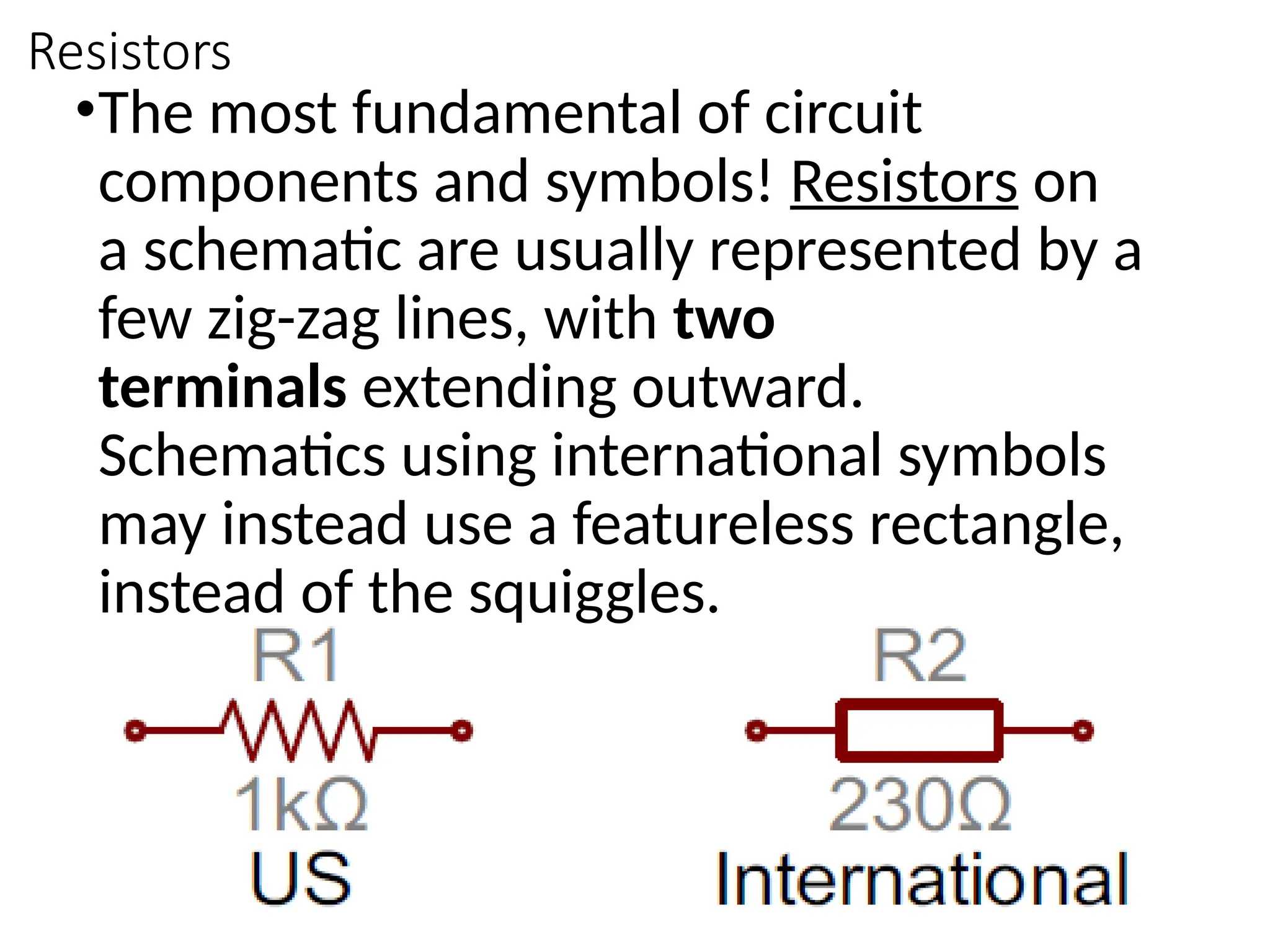
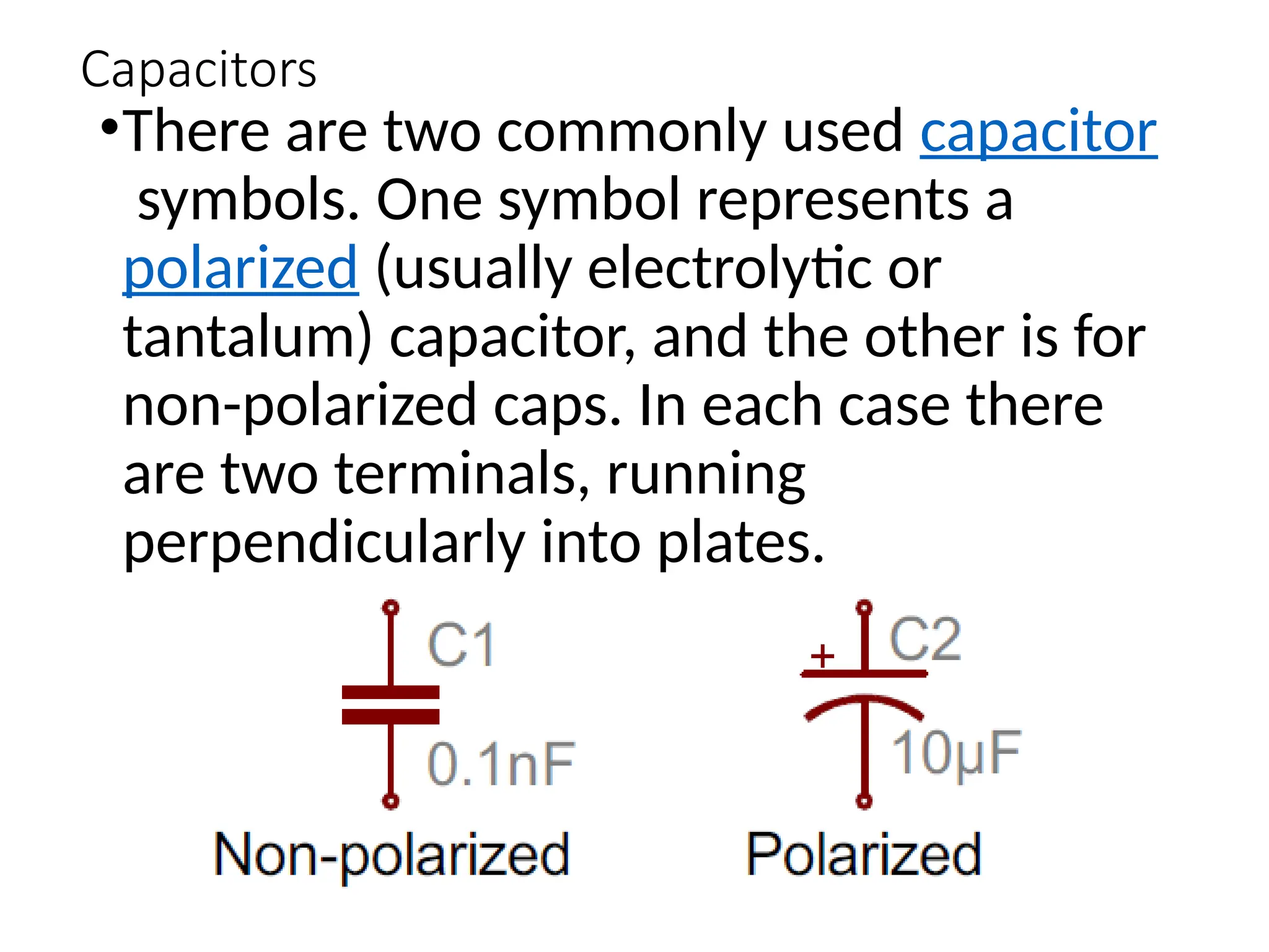
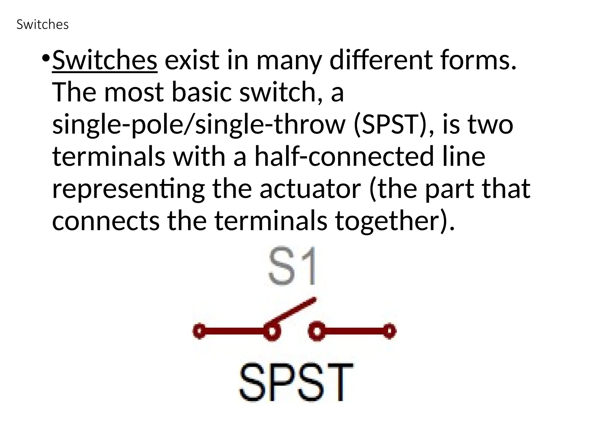
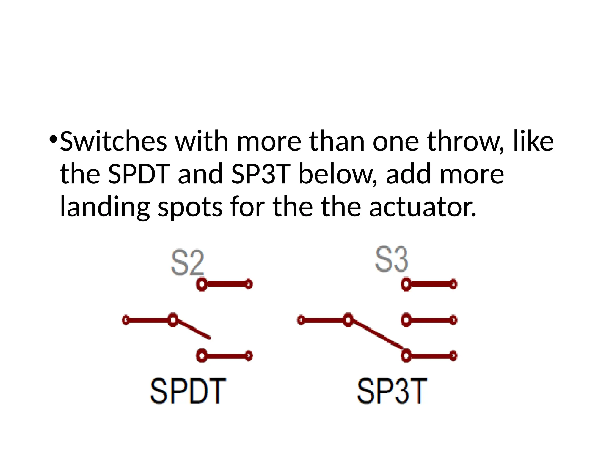
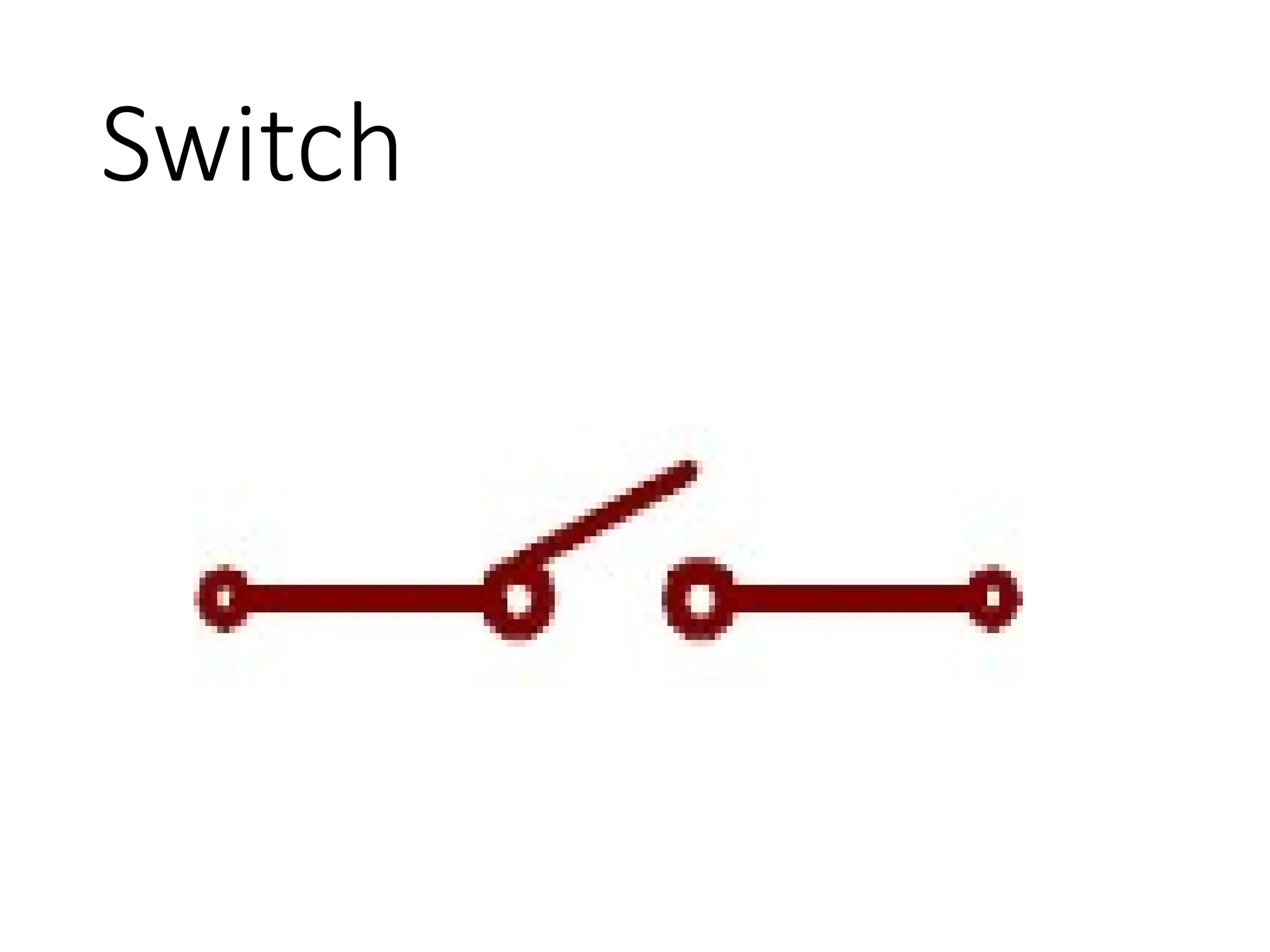
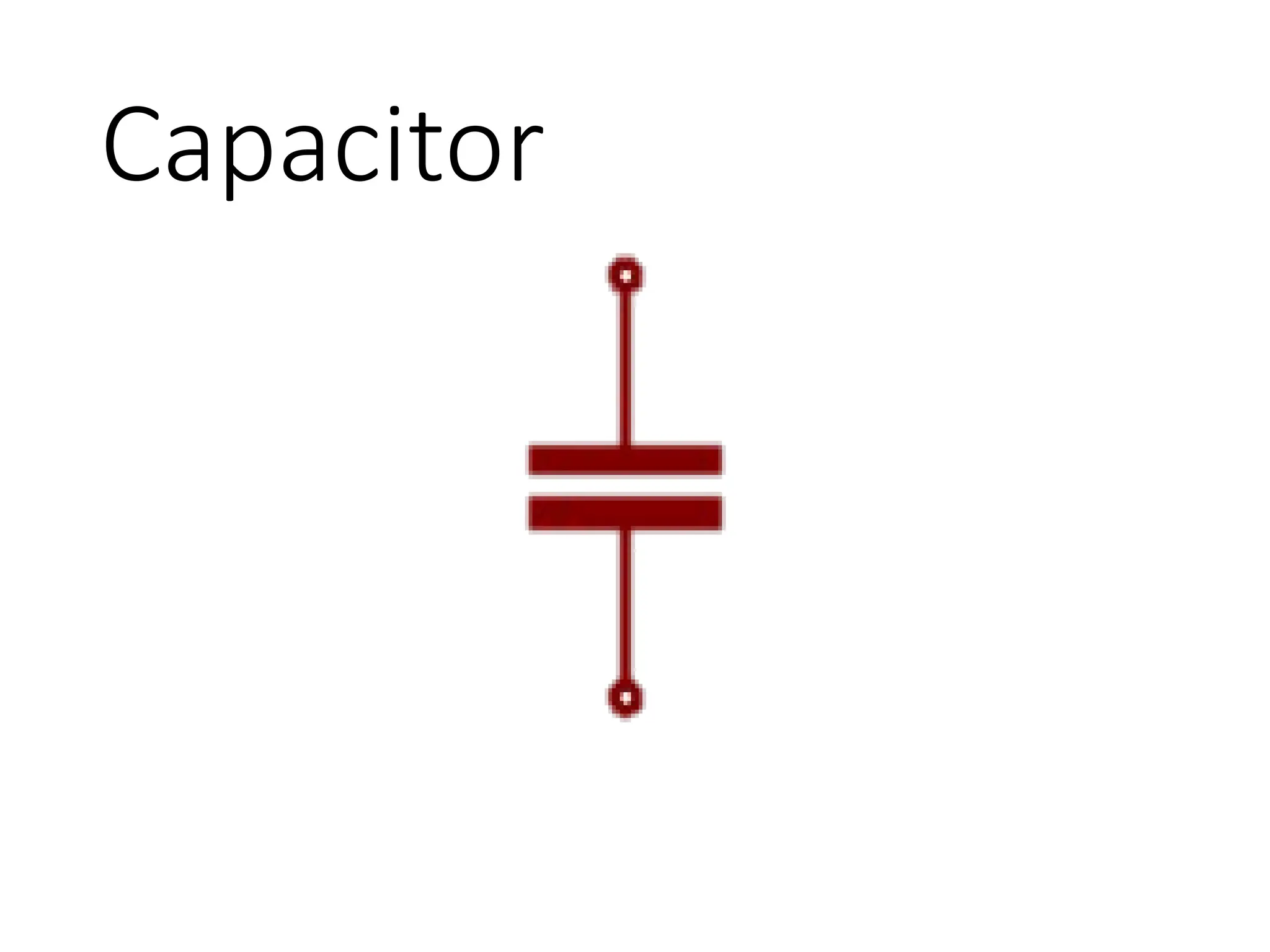
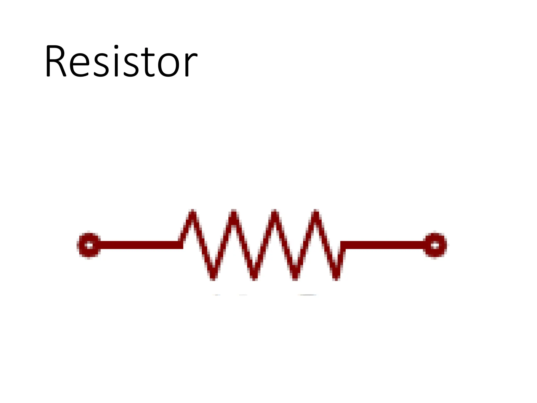
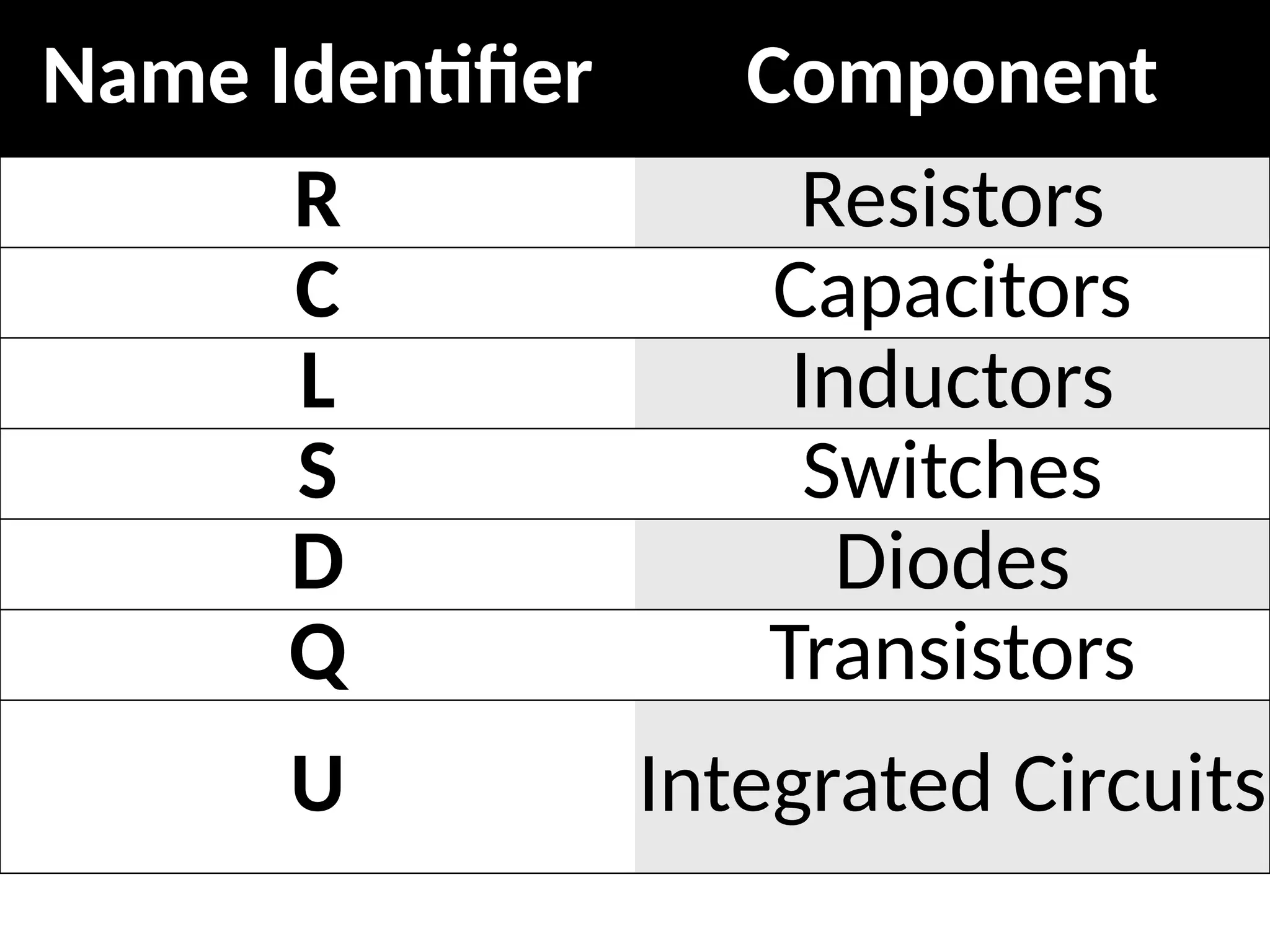
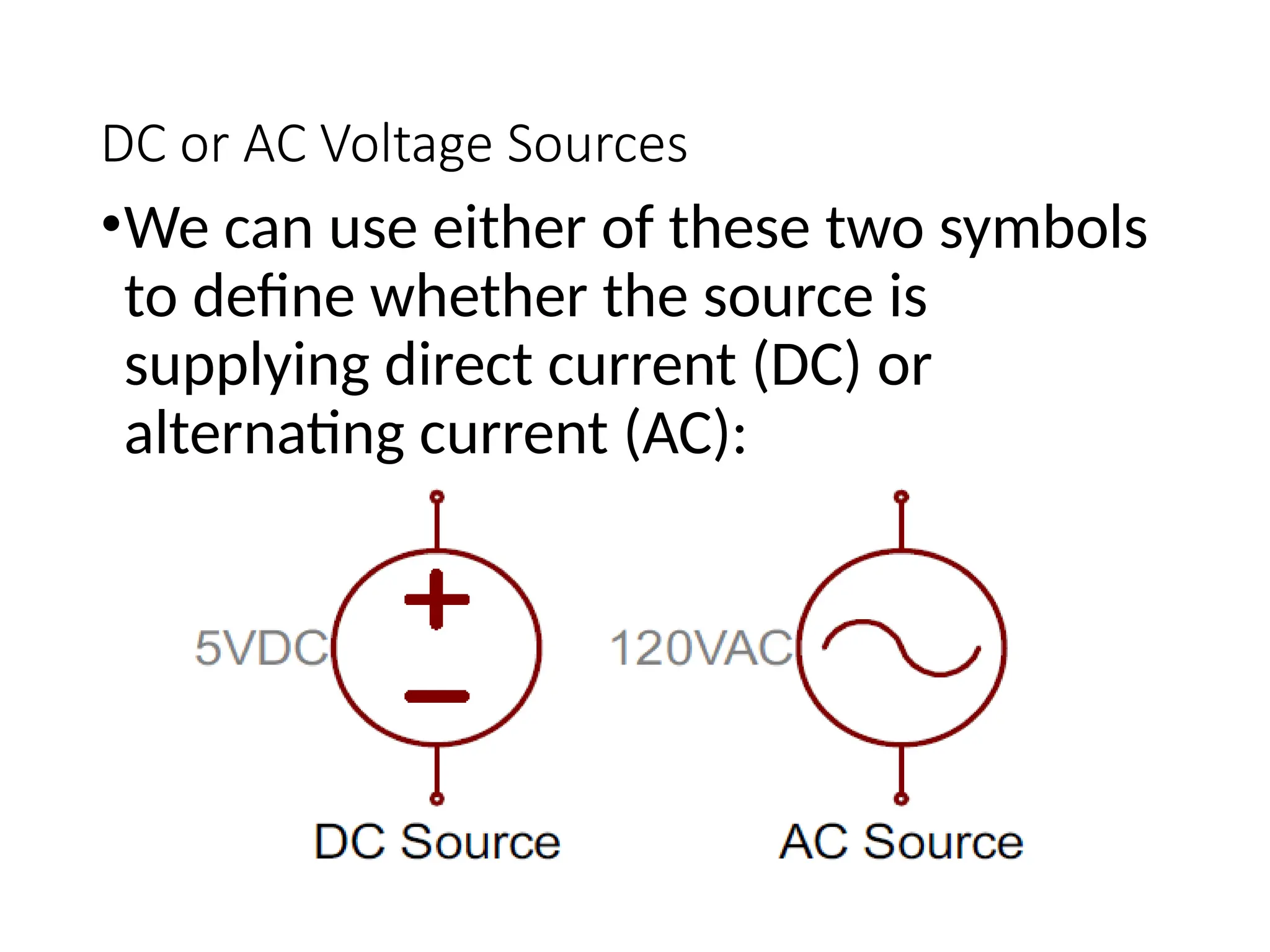
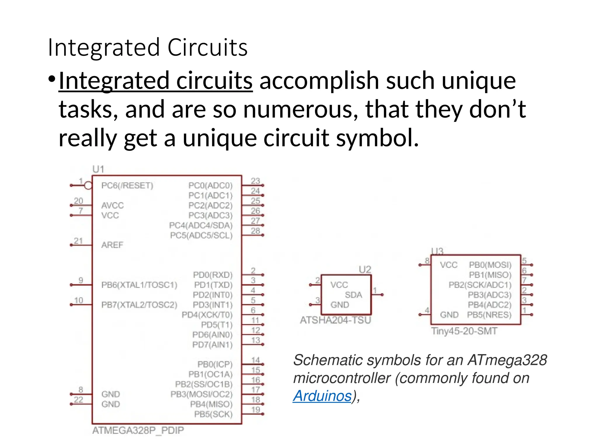
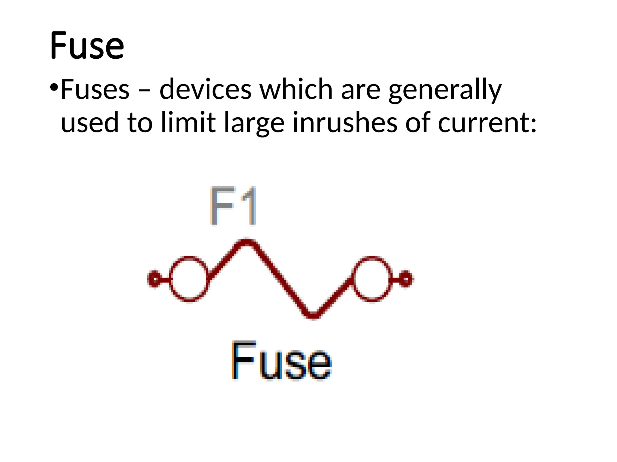
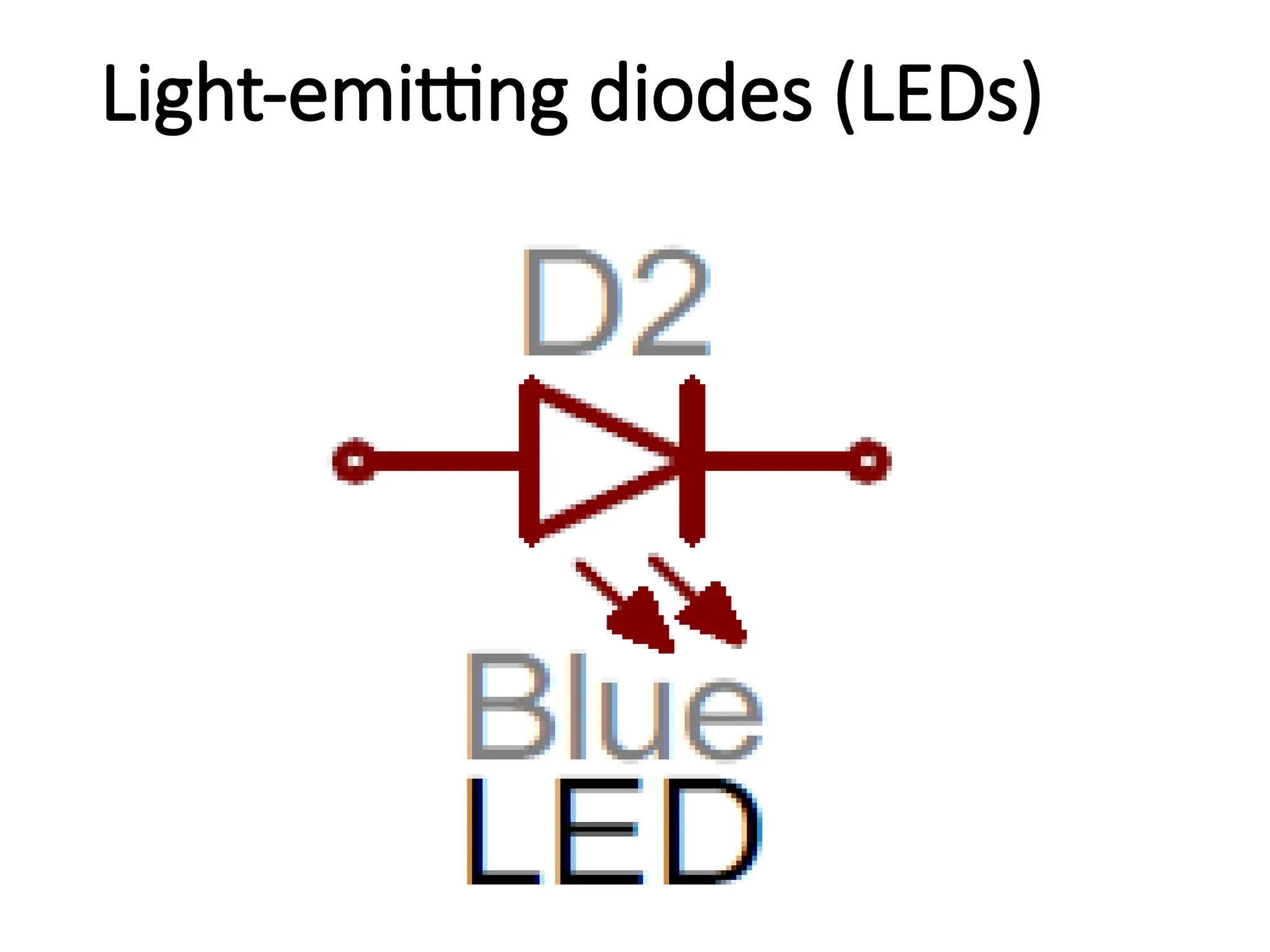
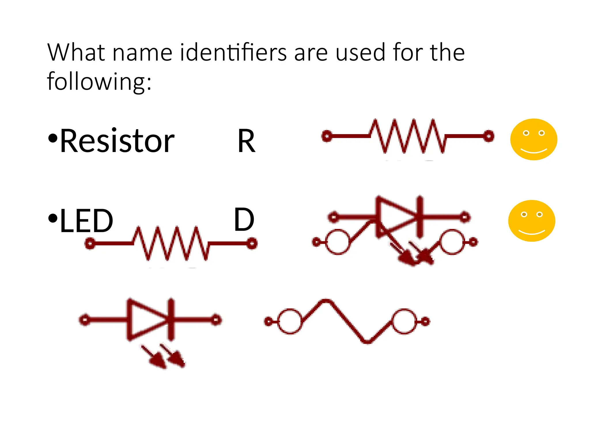
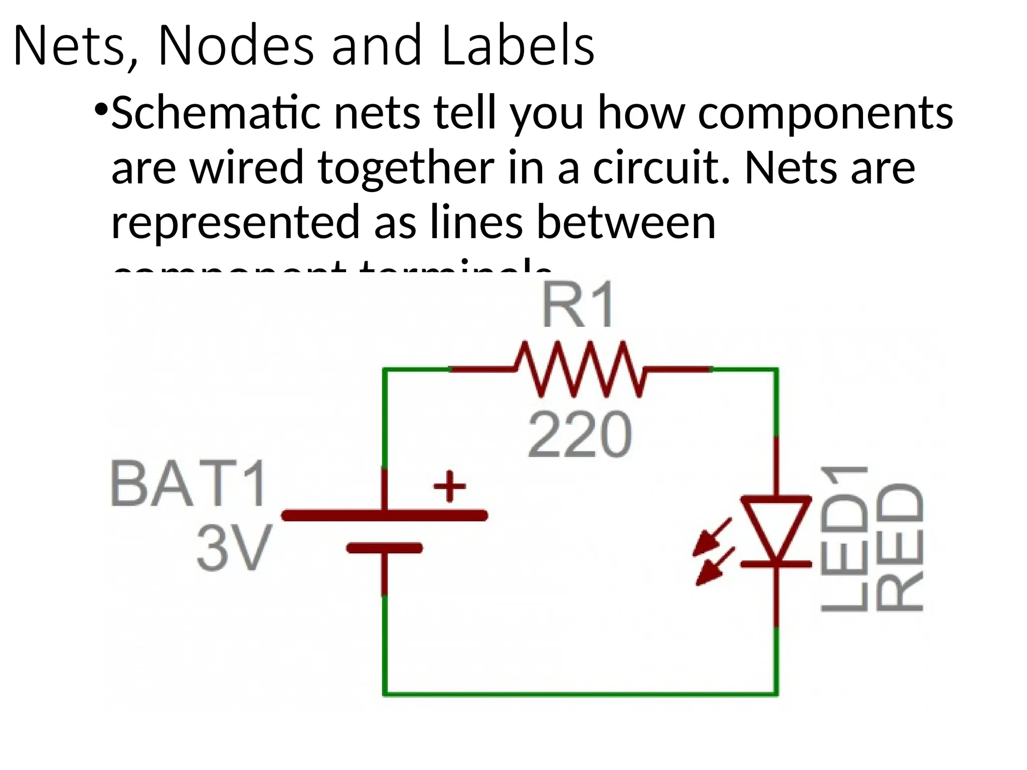
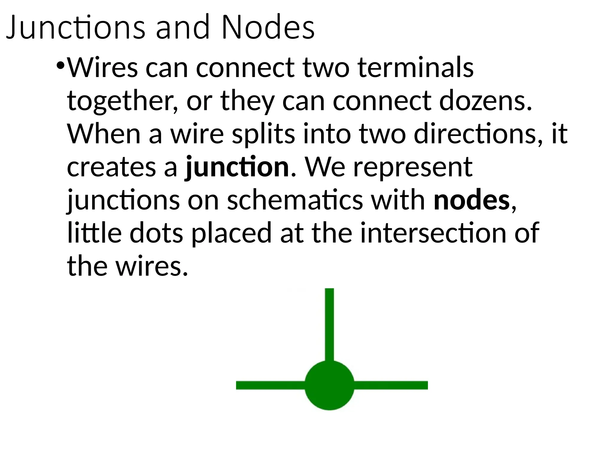
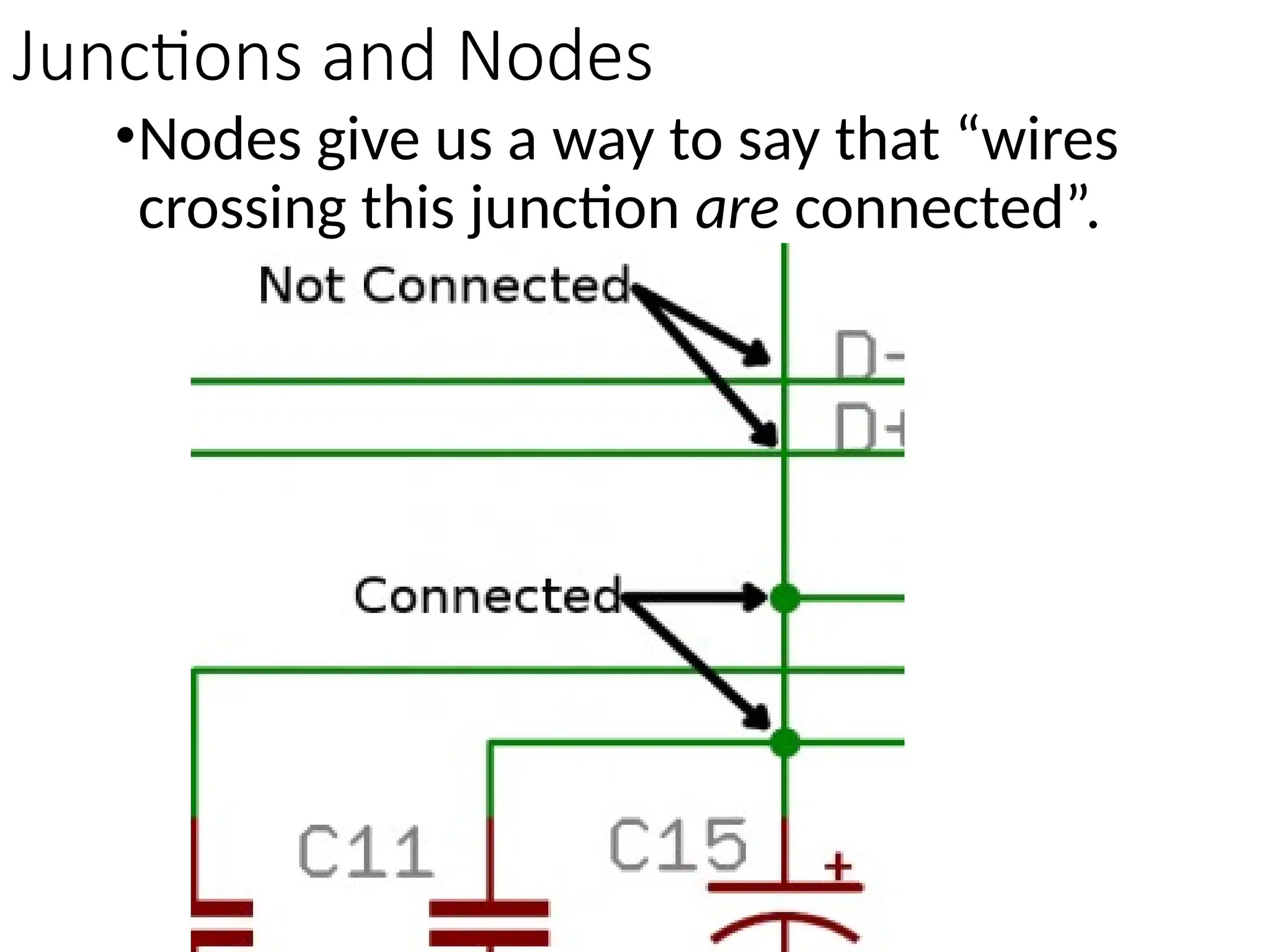
Schematic Diagram
Schematic Diagram
•Schematics are our
map to designing,
building, and
troubleshooting
circuits.
Electricity
•Electricity is the
phenomena associated with
the presence and flow of
electric charges.
ELECTRICITY TERMINOLOGIES
•Polarity
•Having two oppositely charged
poles, one positive and one
negative. Polarity determines the
direction in which current tends to
flow.
•Electrical circuits need to be checked
for polarity prior to energizing.
Current
•Electric current is a flow of
electric charge through a medium.
This charge is typically carried by
moving electrons in a conductor such
as wire. It can also be carried by ions
in an electrolyte. The current was
measured in amperes.
Resistance
•The electrical resistance of an
electrical element is the
opposition to the passage of an
electric current through that
element; the inverse quantity is
electrical conductance, the ease
at which an electric current
passes.
Conductor
•An electrical conductor is
anything that carries or moves
current. Copper is the most
common conductor and used in
wiring. Silver and gold also are
conductors. Some non metallic
conductors would be solutions
containing salts.
Non-Conductors
•Non-conductors are substance etc. that
does not easily conduct heat or electricity.
Those materials which cannot pass
electricity are known as non-conductors.
They do not pass electricity because they do
not have free electrons and ions to help in
flow of current. Non-conductors have large
resistance and zero conductivity. They are
widely used in coating of electric wires.
Plastic, glass, rubbers, ceramic are examples
of non-conductors. Moreover, they are also
known as insulators.
Dynamic VS Static Electricity
•Static electricity refers to the
accumulation of excess electric
charge in a region with poor
electrical conductivity (an
insulator), such that the charge
accumulation persists.
Dynamic electricity refers to the
movement of the charges in good
electrical conductors.
Resistors
•The most fundamental of circuit
components and symbols! Resistors on
a schematic are usually represented by a
few zig-zag lines, with two
terminals extending outward.
Schematics using international symbols
may instead use a featureless rectangle,
instead of the squiggles.
Capacitors
•There are two commonly used capacitor
symbols. One symbol represents a
polarized (usually electrolytic or
tantalum) capacitor, and the other is for
non-polarized caps. In each case there
are two terminals, running
perpendicularly into plates.
Switches
•Switches exist in many different forms.
The most basic switch, a
single-pole/single-throw (SPST), is two
terminals with a half-connected line
representing the actuator (the part that
connects the terminals together).
•Switches with more than one throw, like
the SPDT and SP3T below, add more
landing spots for the the actuator.
Electronic Components with
their Respective name
identifier
Switch
Capacitor
Resistor
Names and Values
•Values help define exactly
what a component is. For
schematic components like
resistors and capacitors, the
value tells us how many ohms
or farads they have.
Names and Values
•For other components, like
integrated circuits, the value
may just be the name of the
chip.
Names and Values
•The value of a
schematic component
calls out its most
important
characteristic.
Names and Values
•Component NAMES are
usually a combination
of one or two letters
and a number.
Names and Values
•The letter part of the
name identifies the type
of component – R’s for
resistors, C’s for
capacitors, U’s for
integrated circuits, etc.
Names and Values
•Component
name on a
schematic should
be unique.
R2
220
Names and Values
•Component names
help us reference
specific points in
schematics.
Names and Values
•The prefixes of
names are pretty
well standardized.
Name Identifier Component
R Resistors
C Capacitors
L Inductors
S Switches
D Diodes
Q Transistors
U Integrated Circuits
DC or AC Voltage Sources
•We can use either of these two symbols
to define whether the source is
supplying direct current (DC) or
alternating current (AC):
Integrated Circuits
•Integrated circuits accomplish such unique
tasks, and are so numerous, that they don’t
really get a unique circuit symbol.
Schematic symbols for an ATmega328
microcontroller (commonly found on
Arduinos),
Batteries
•Batteries, whether they’re those
cylindrical, alkaline AA’s or rechargeable
lithium-polymers, usually look like a pair
of disproportionate, parallel lines:
Fuse
•Fuses – devices which are generally
used to limit large inrushes of current:
Light-emitting diodes (LEDs)
What name identifiers are used for the
following:
•Resistor R
•LED D
Reading Schematics
•Understanding which
components are which on
a schematic is more than
half the battle towards
comprehending it.
Nets, Nodes and Labels
•Schematic nets tell you how components
are wired together in a circuit. Nets are
represented as lines between
component terminals.
Junctions and Nodes
•Wires can connect two terminals
together, or they can connect dozens.
When a wire splits into two directions, it
creates a junction. We represent
junctions on schematics with nodes,
little dots placed at the intersection of
the wires.
Junctions and Nodes
•Nodes give us a way to say that “wires
crossing this junction are connected”.
Activity
•Create a simple diagram of
a LED connected to a SPST
switch and a DC power
source.
Quiz

Creating Schematic Diagram presentation.pptx

  • 1.
  • 2.
    Schematic Diagram •Schematics areour map to designing, building, and troubleshooting circuits.
  • 3.
    Electricity •Electricity is the phenomenaassociated with the presence and flow of electric charges.
  • 4.
    ELECTRICITY TERMINOLOGIES •Polarity •Having twooppositely charged poles, one positive and one negative. Polarity determines the direction in which current tends to flow. •Electrical circuits need to be checked for polarity prior to energizing.
  • 5.
    Current •Electric current isa flow of electric charge through a medium. This charge is typically carried by moving electrons in a conductor such as wire. It can also be carried by ions in an electrolyte. The current was measured in amperes.
  • 6.
    Resistance •The electrical resistanceof an electrical element is the opposition to the passage of an electric current through that element; the inverse quantity is electrical conductance, the ease at which an electric current passes.
  • 7.
    Conductor •An electrical conductoris anything that carries or moves current. Copper is the most common conductor and used in wiring. Silver and gold also are conductors. Some non metallic conductors would be solutions containing salts.
  • 8.
    Non-Conductors •Non-conductors are substanceetc. that does not easily conduct heat or electricity. Those materials which cannot pass electricity are known as non-conductors. They do not pass electricity because they do not have free electrons and ions to help in flow of current. Non-conductors have large resistance and zero conductivity. They are widely used in coating of electric wires. Plastic, glass, rubbers, ceramic are examples of non-conductors. Moreover, they are also known as insulators.
  • 9.
    Dynamic VS StaticElectricity •Static electricity refers to the accumulation of excess electric charge in a region with poor electrical conductivity (an insulator), such that the charge accumulation persists. Dynamic electricity refers to the movement of the charges in good electrical conductors.
  • 10.
    Resistors •The most fundamentalof circuit components and symbols! Resistors on a schematic are usually represented by a few zig-zag lines, with two terminals extending outward. Schematics using international symbols may instead use a featureless rectangle, instead of the squiggles.
  • 11.
    Capacitors •There are twocommonly used capacitor symbols. One symbol represents a polarized (usually electrolytic or tantalum) capacitor, and the other is for non-polarized caps. In each case there are two terminals, running perpendicularly into plates.
  • 12.
    Switches •Switches exist inmany different forms. The most basic switch, a single-pole/single-throw (SPST), is two terminals with a half-connected line representing the actuator (the part that connects the terminals together).
  • 13.
    •Switches with morethan one throw, like the SPDT and SP3T below, add more landing spots for the the actuator.
  • 14.
    Electronic Components with theirRespective name identifier
  • 15.
  • 16.
  • 17.
  • 18.
    Names and Values •Valueshelp define exactly what a component is. For schematic components like resistors and capacitors, the value tells us how many ohms or farads they have.
  • 19.
    Names and Values •Forother components, like integrated circuits, the value may just be the name of the chip.
  • 20.
    Names and Values •Thevalue of a schematic component calls out its most important characteristic.
  • 21.
    Names and Values •ComponentNAMES are usually a combination of one or two letters and a number.
  • 22.
    Names and Values •Theletter part of the name identifies the type of component – R’s for resistors, C’s for capacitors, U’s for integrated circuits, etc.
  • 23.
    Names and Values •Component nameon a schematic should be unique.
  • 24.
  • 25.
    Names and Values •Componentnames help us reference specific points in schematics.
  • 26.
    Names and Values •Theprefixes of names are pretty well standardized.
  • 27.
    Name Identifier Component RResistors C Capacitors L Inductors S Switches D Diodes Q Transistors U Integrated Circuits
  • 28.
    DC or ACVoltage Sources •We can use either of these two symbols to define whether the source is supplying direct current (DC) or alternating current (AC):
  • 29.
    Integrated Circuits •Integrated circuitsaccomplish such unique tasks, and are so numerous, that they don’t really get a unique circuit symbol. Schematic symbols for an ATmega328 microcontroller (commonly found on Arduinos),
  • 30.
    Batteries •Batteries, whether they’rethose cylindrical, alkaline AA’s or rechargeable lithium-polymers, usually look like a pair of disproportionate, parallel lines:
  • 31.
    Fuse •Fuses – deviceswhich are generally used to limit large inrushes of current:
  • 32.
  • 33.
    What name identifiersare used for the following: •Resistor R •LED D
  • 34.
    Reading Schematics •Understanding which componentsare which on a schematic is more than half the battle towards comprehending it.
  • 35.
    Nets, Nodes andLabels •Schematic nets tell you how components are wired together in a circuit. Nets are represented as lines between component terminals.
  • 36.
    Junctions and Nodes •Wirescan connect two terminals together, or they can connect dozens. When a wire splits into two directions, it creates a junction. We represent junctions on schematics with nodes, little dots placed at the intersection of the wires.
  • 37.
    Junctions and Nodes •Nodesgive us a way to say that “wires crossing this junction are connected”.
  • 38.
    Activity •Create a simplediagram of a LED connected to a SPST switch and a DC power source.
  • 39.

Editor's Notes