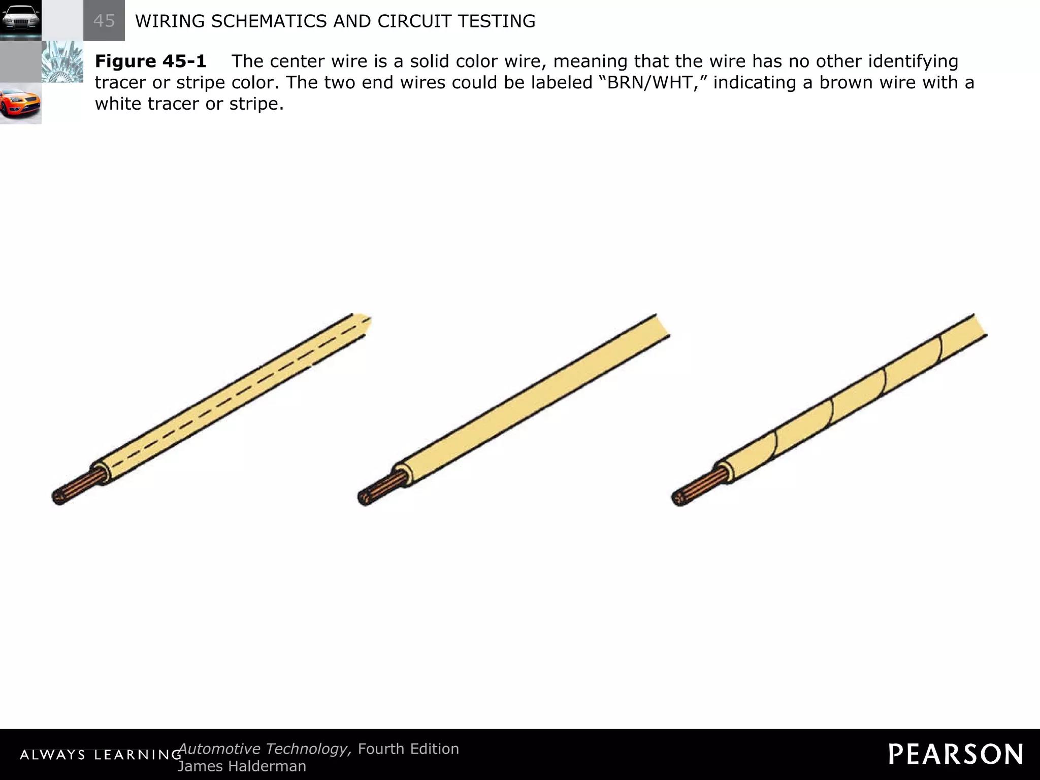
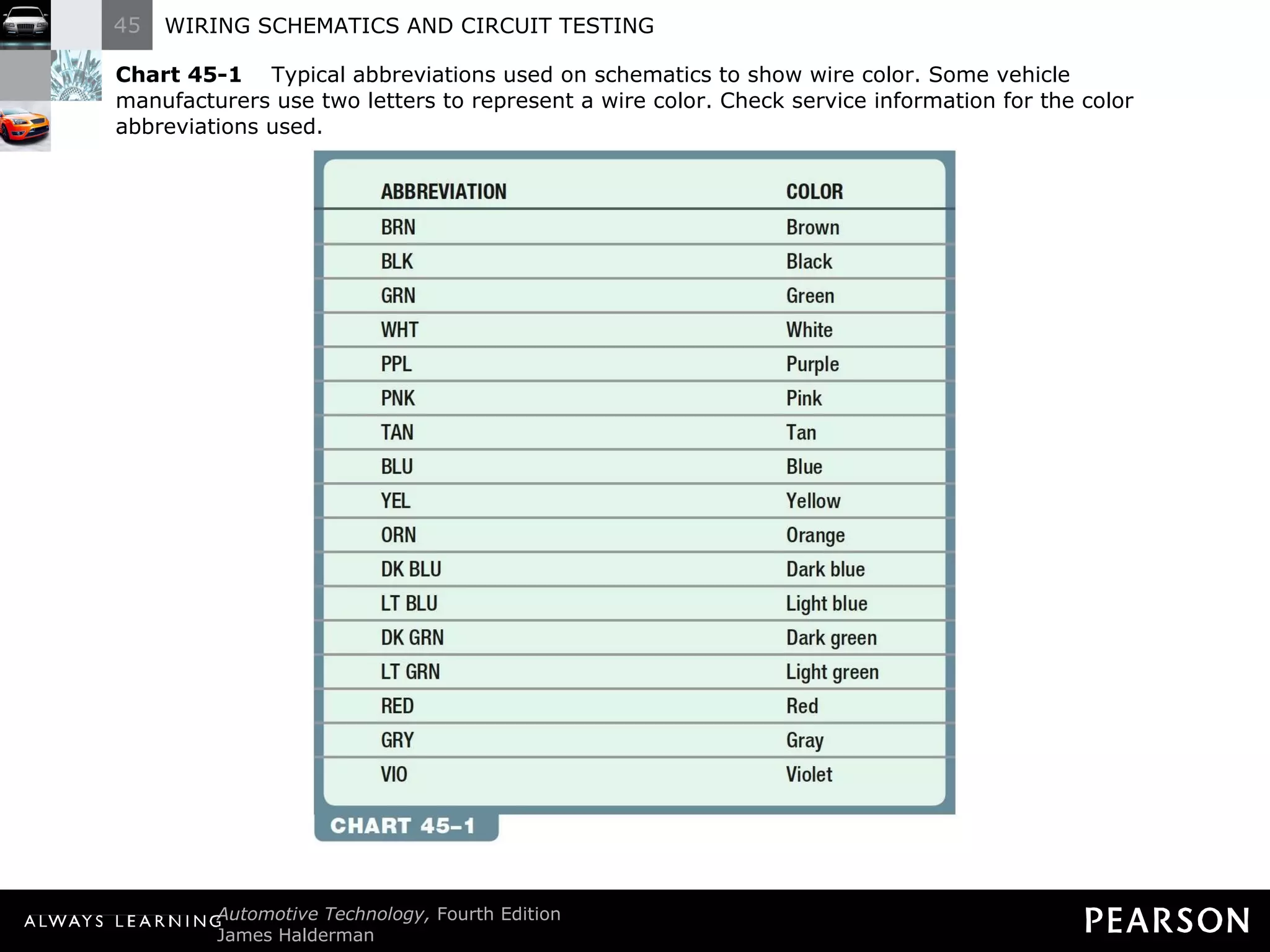
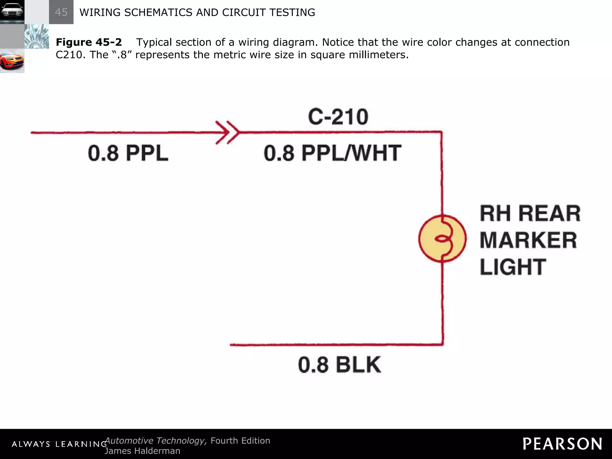
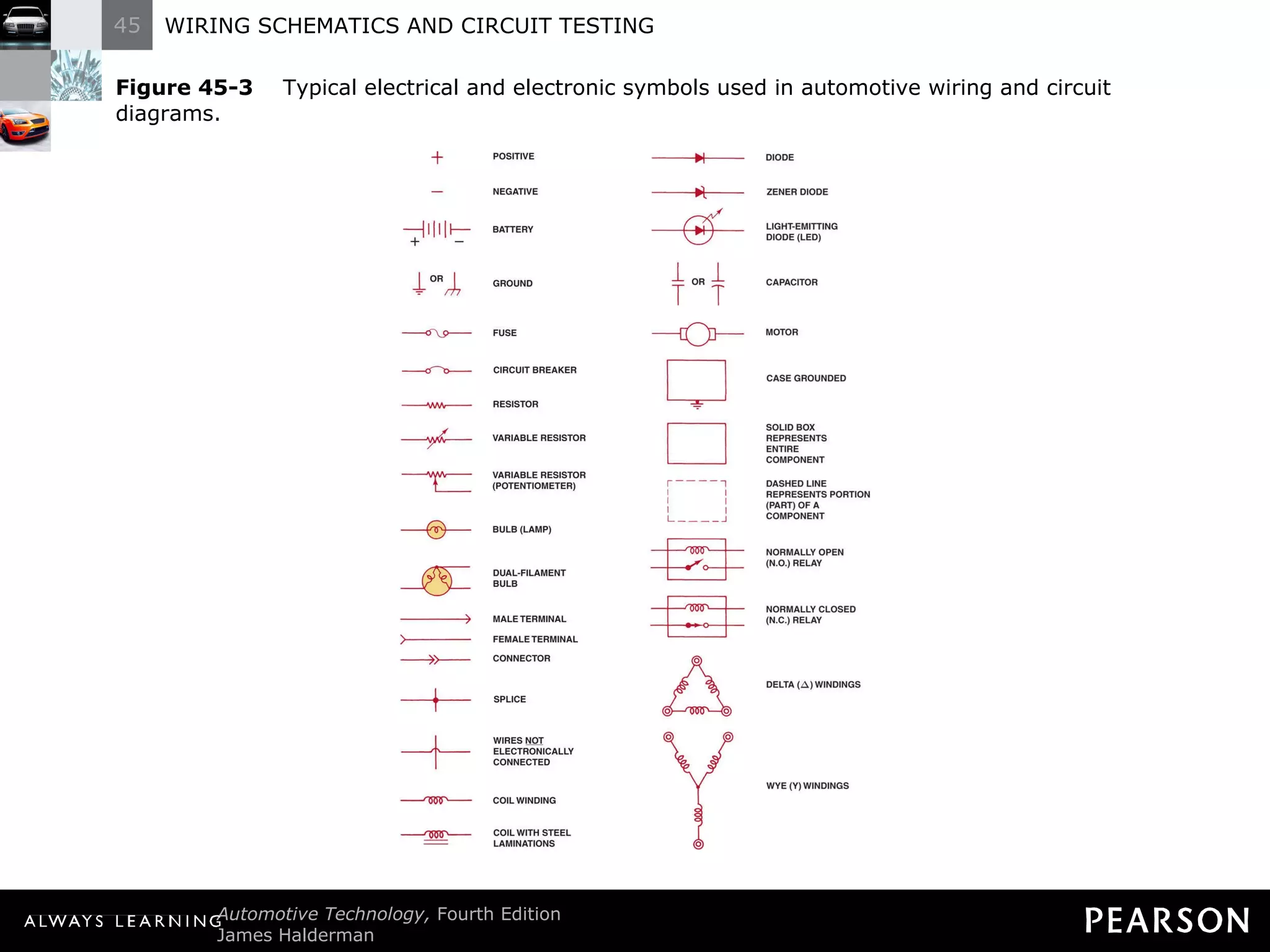
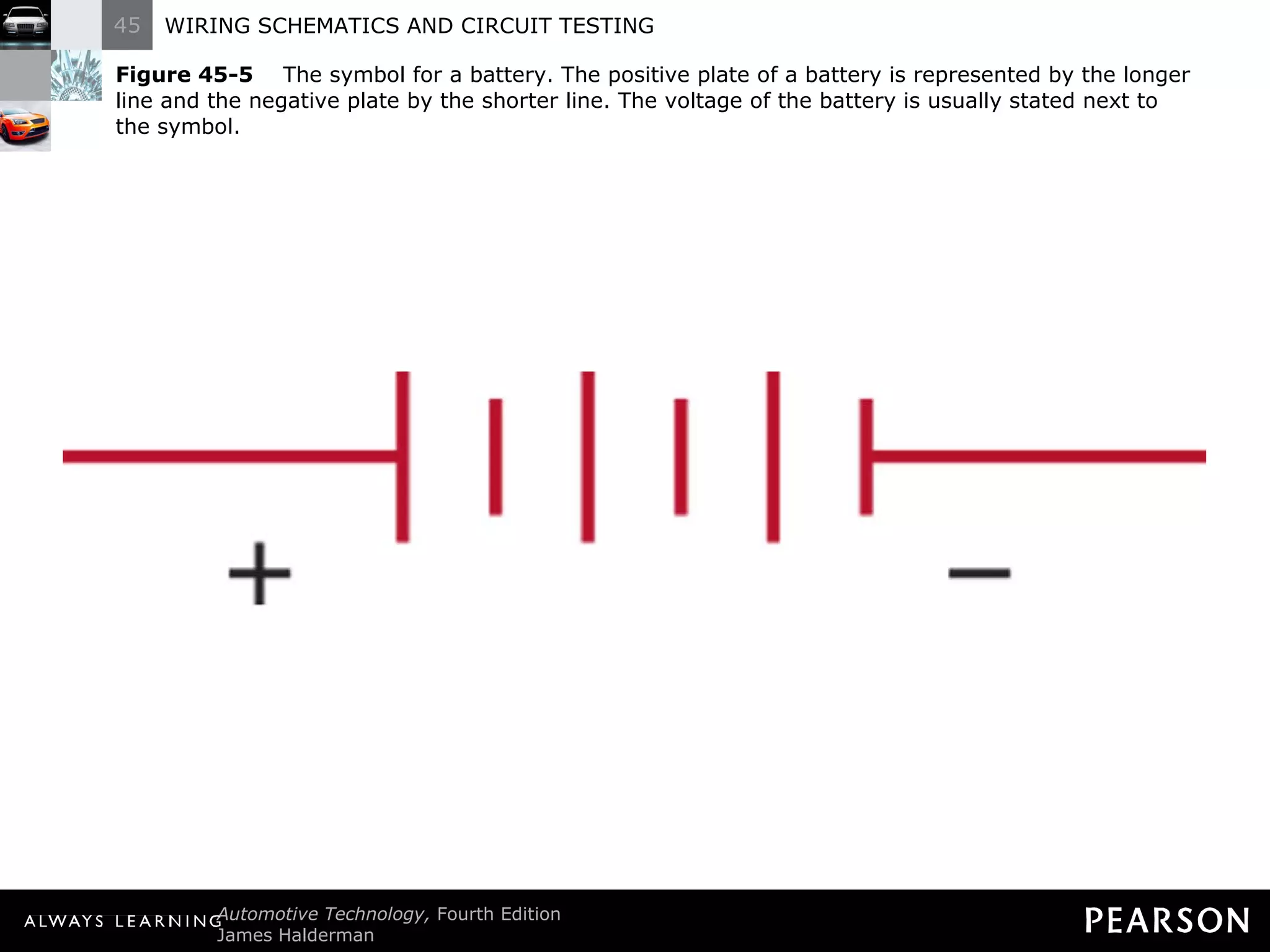
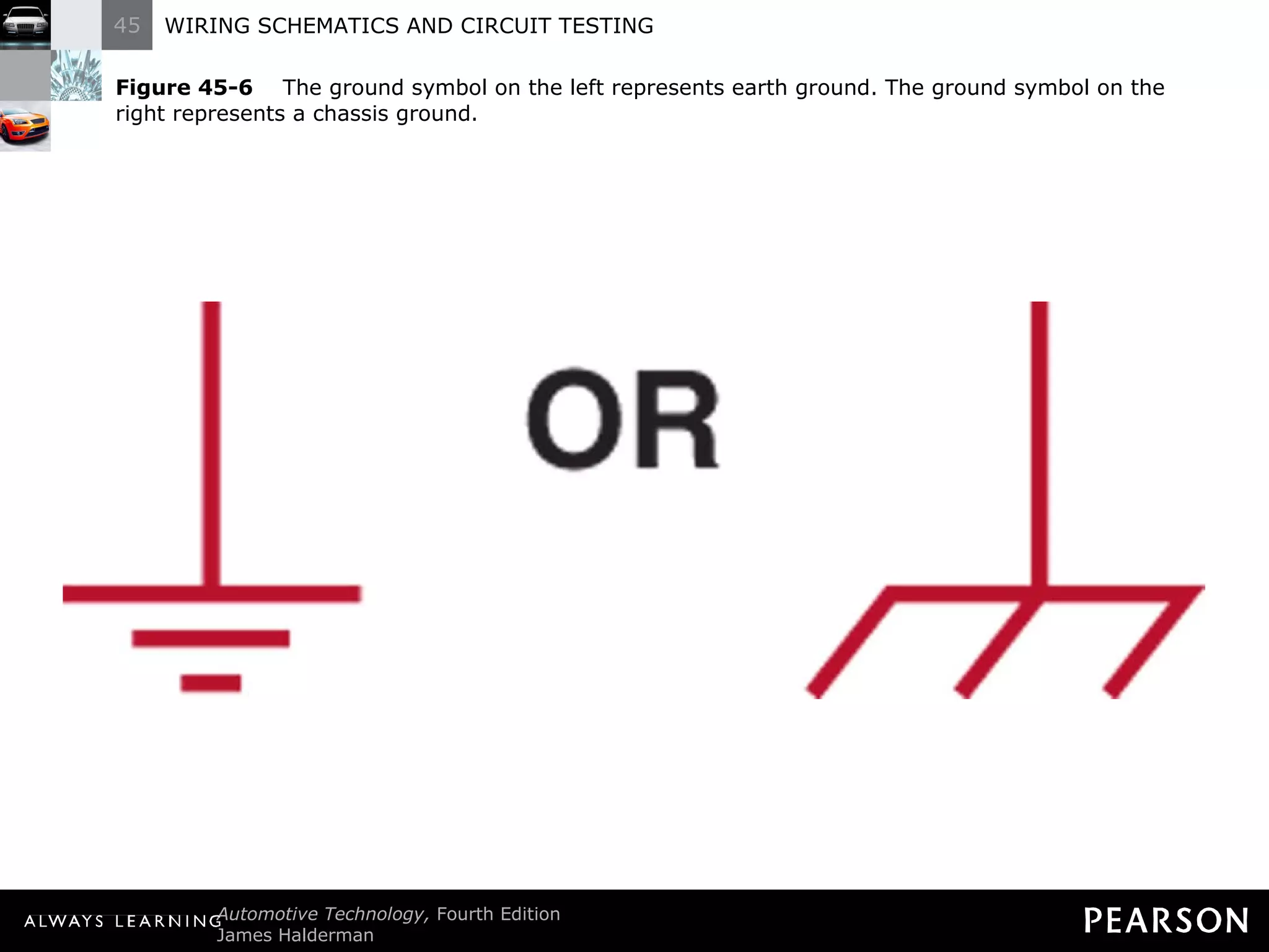
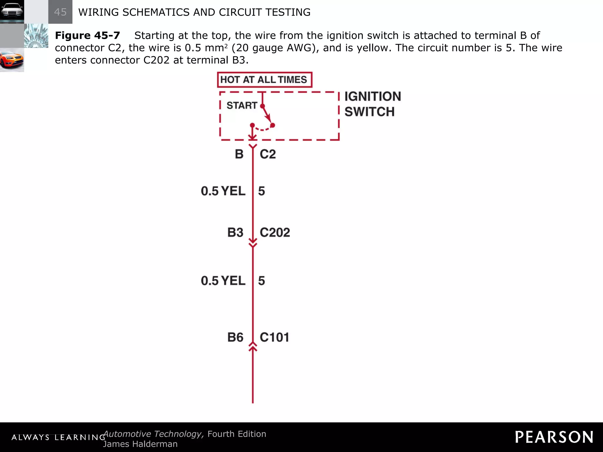
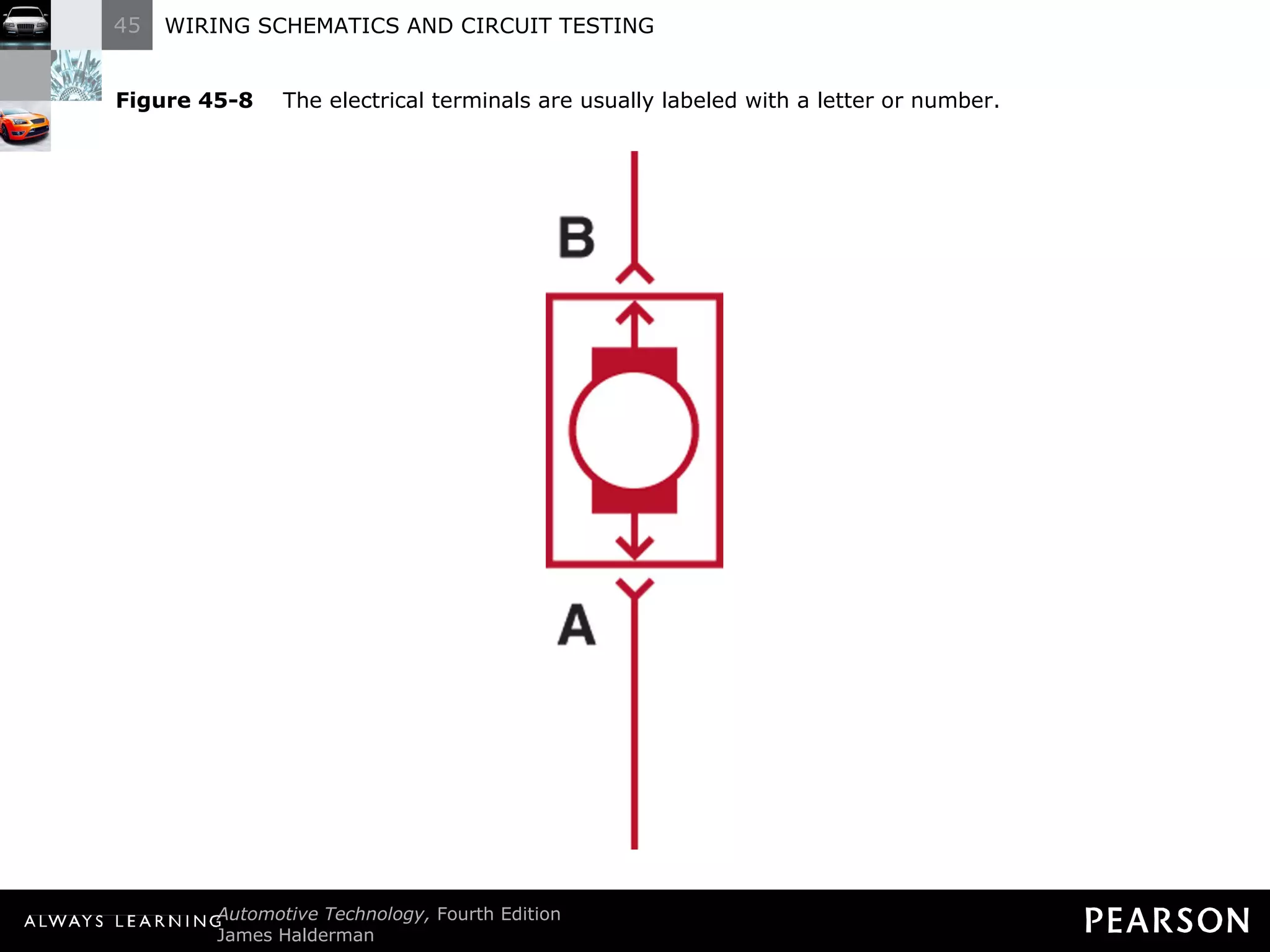
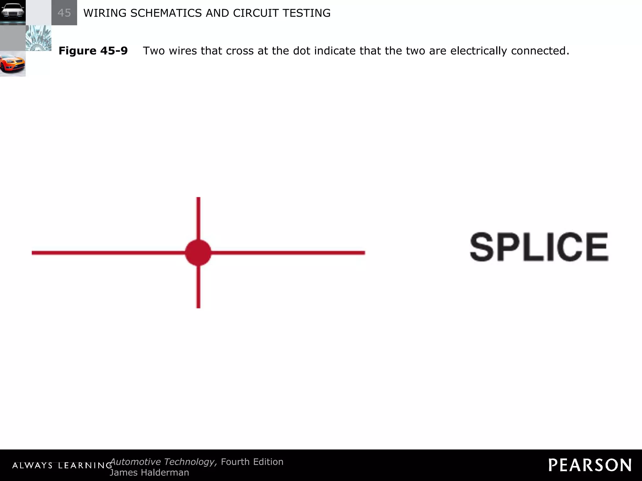
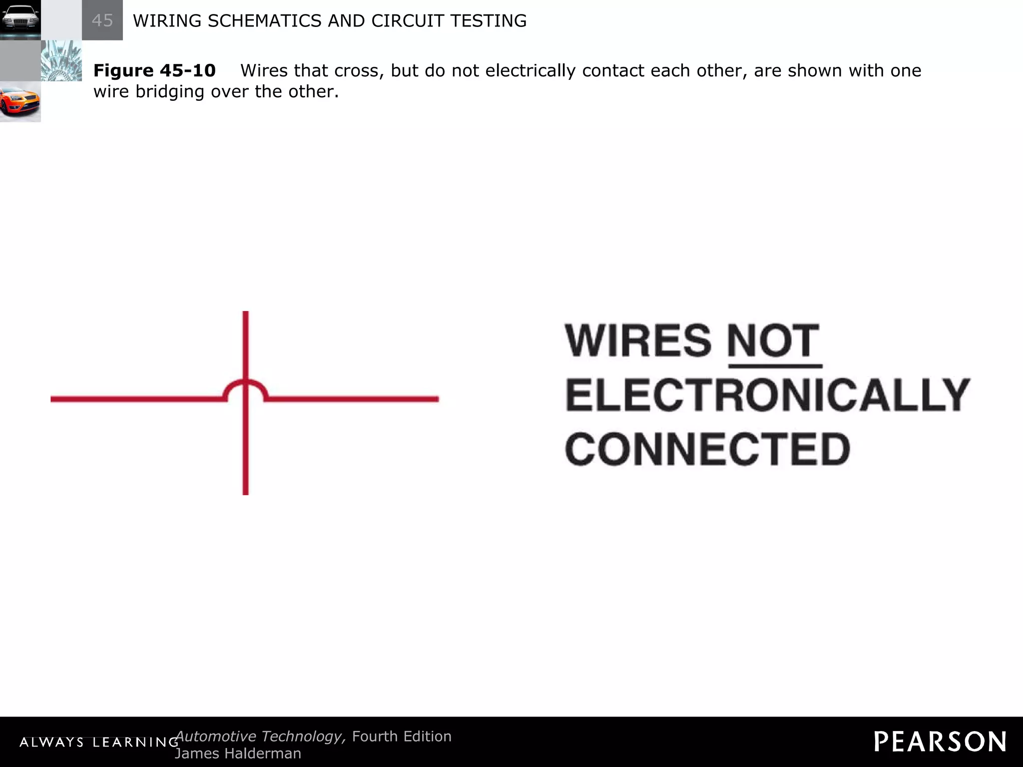
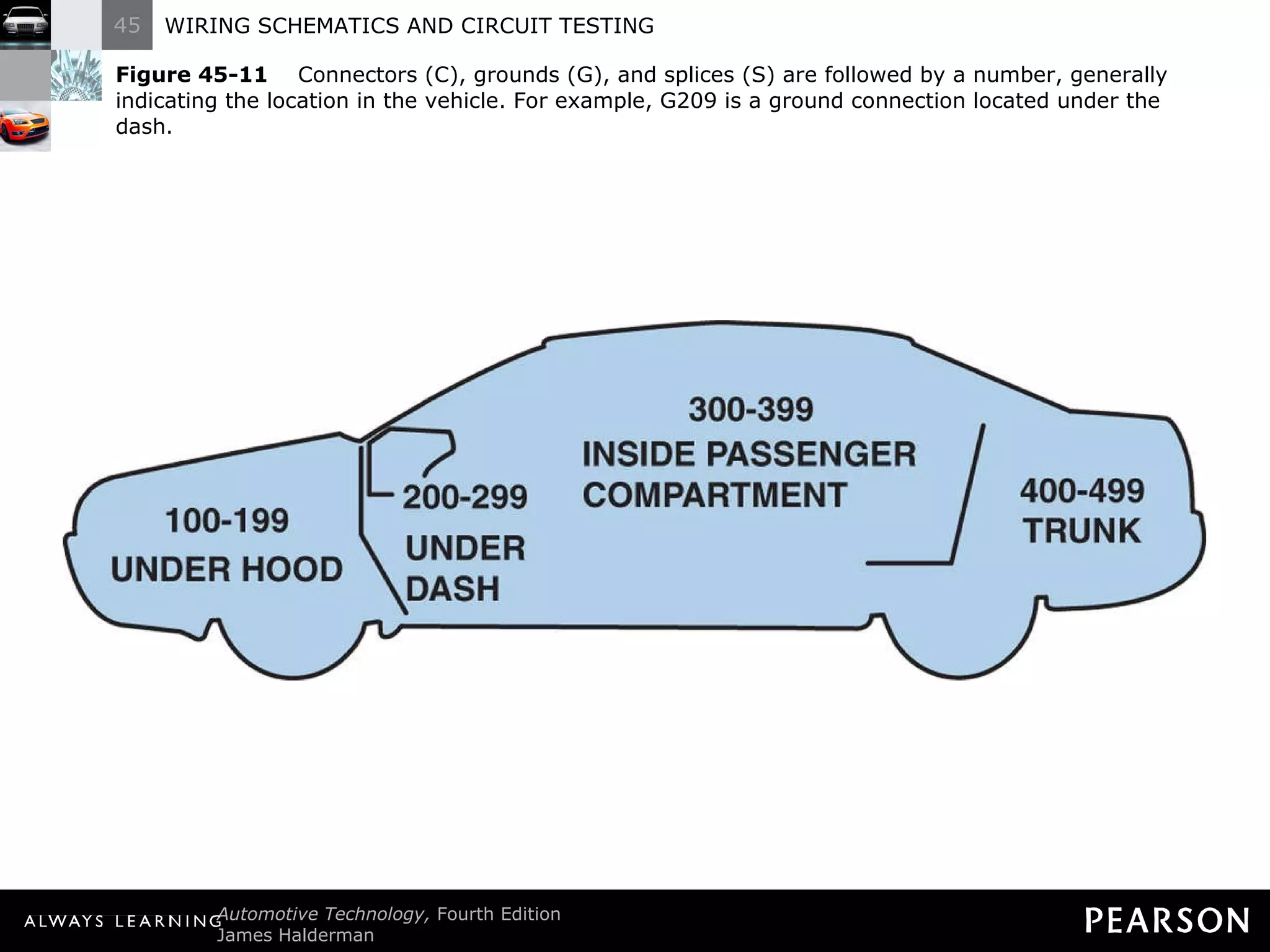
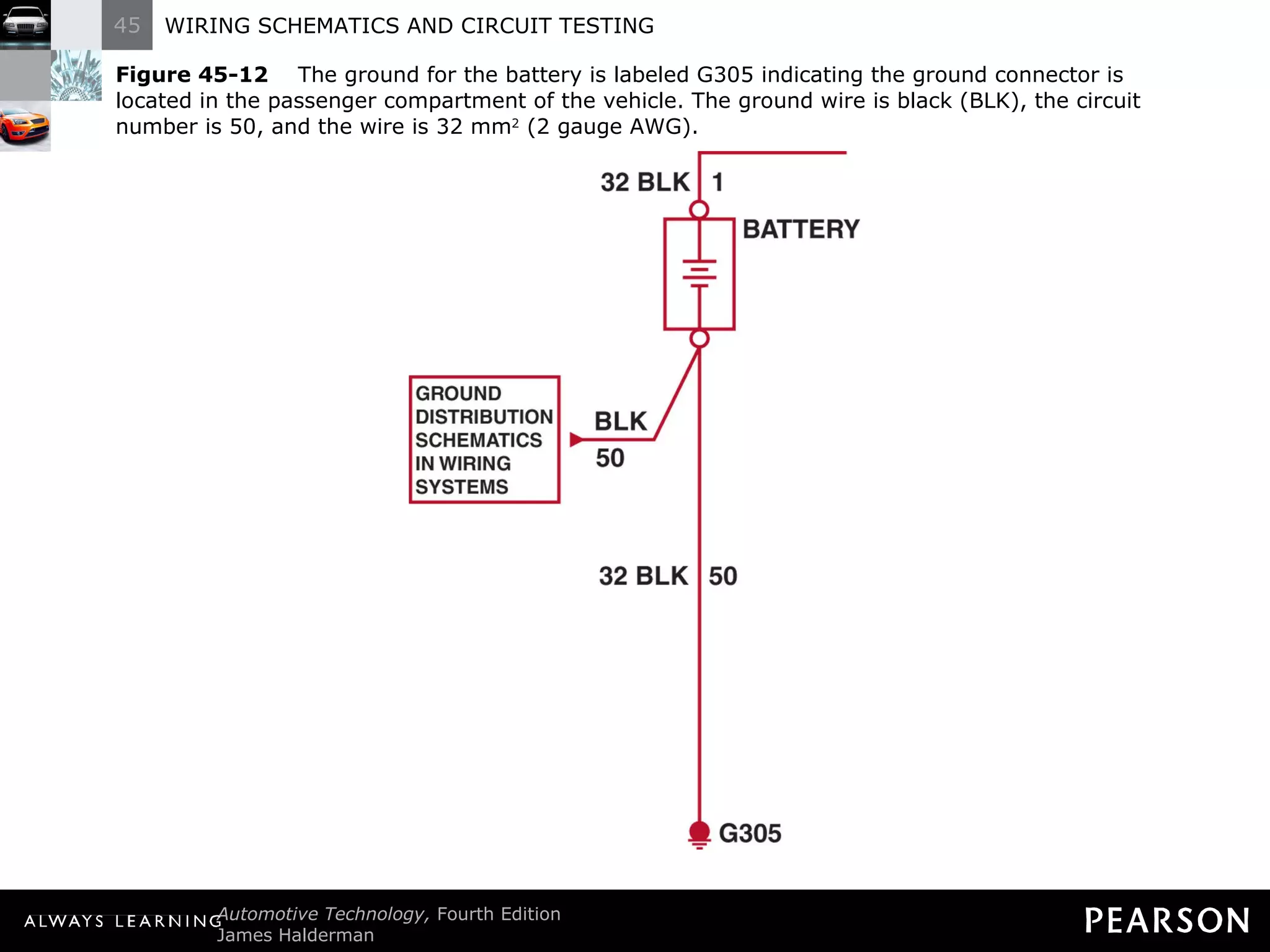
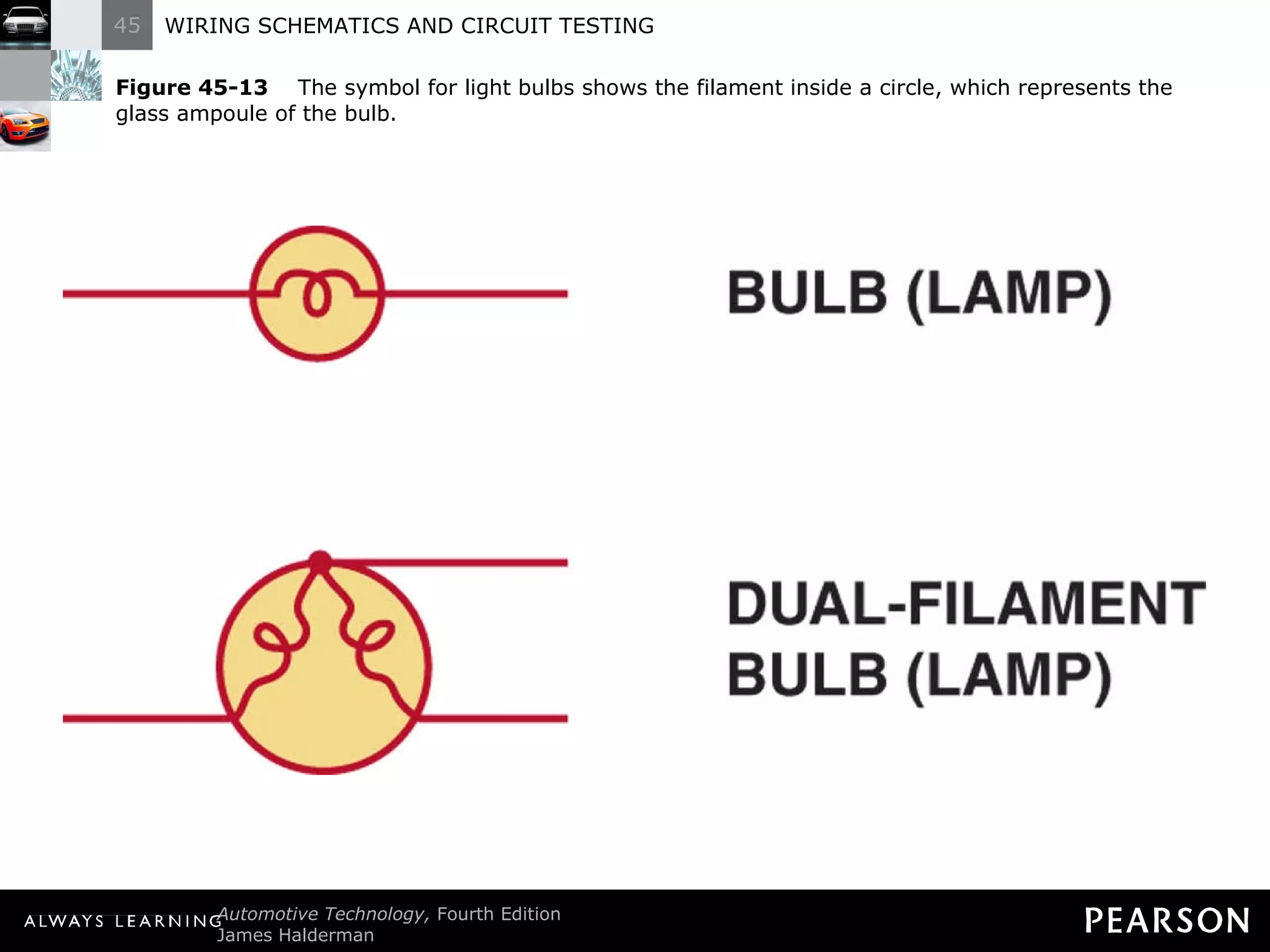
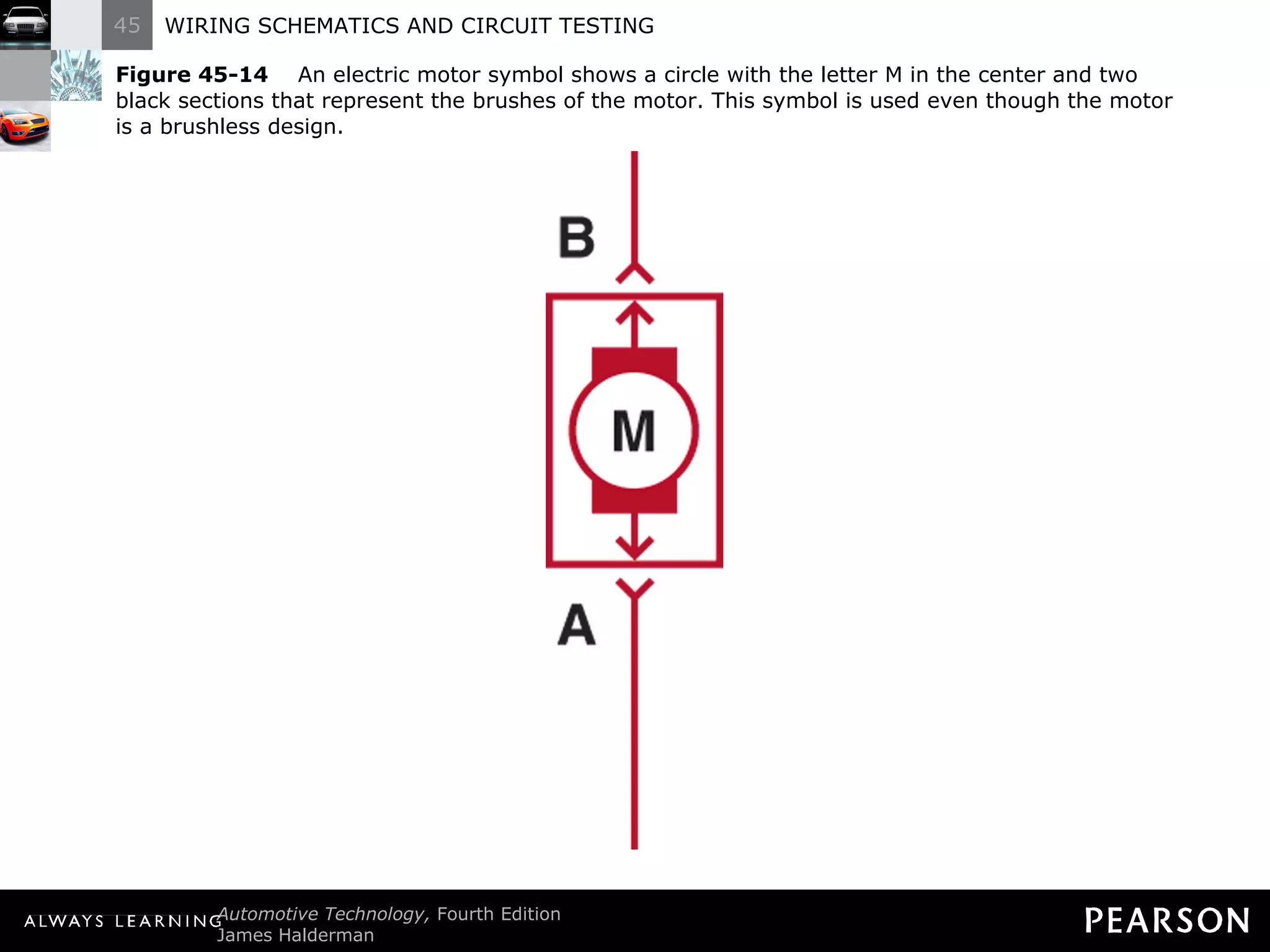
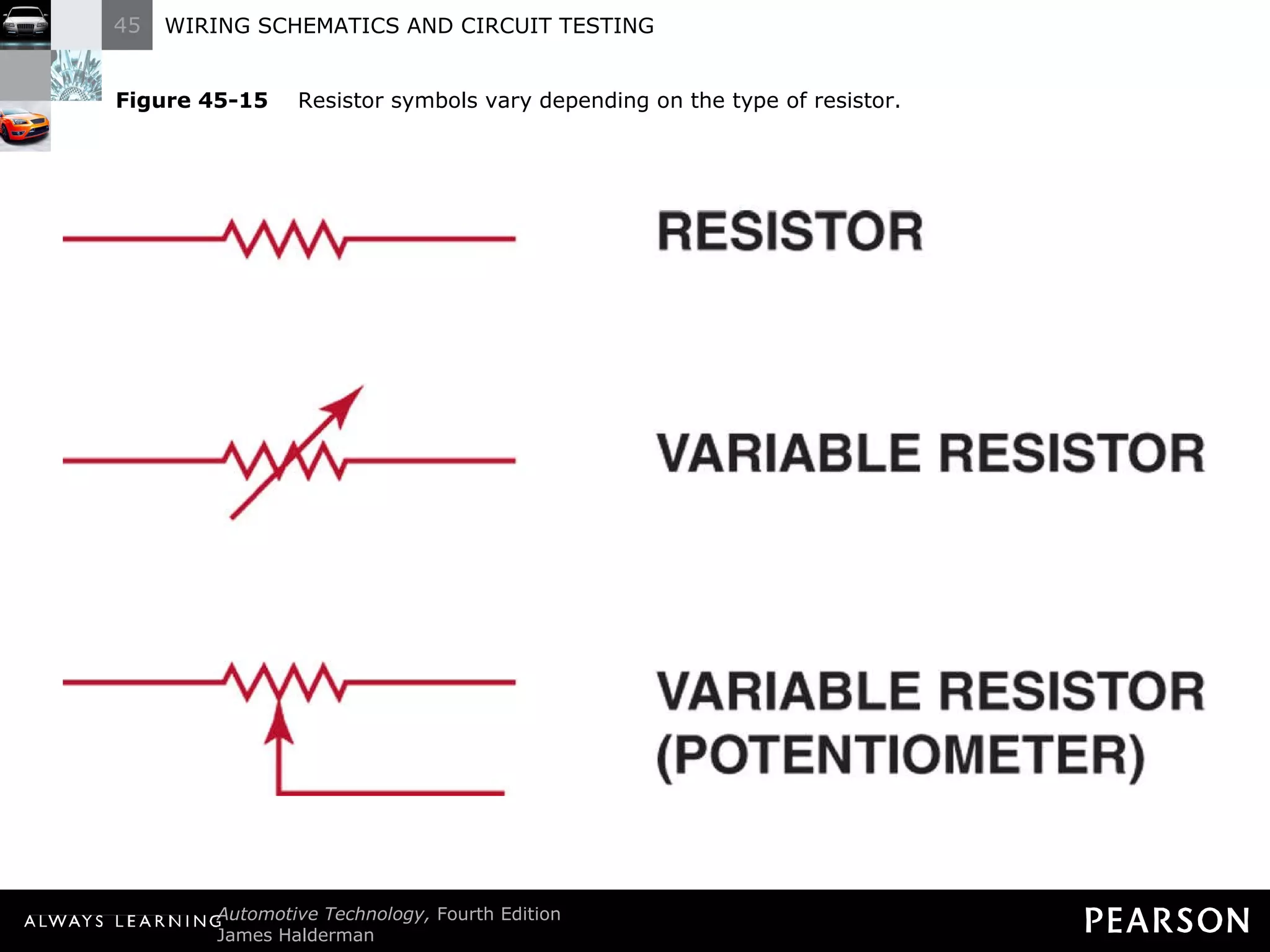
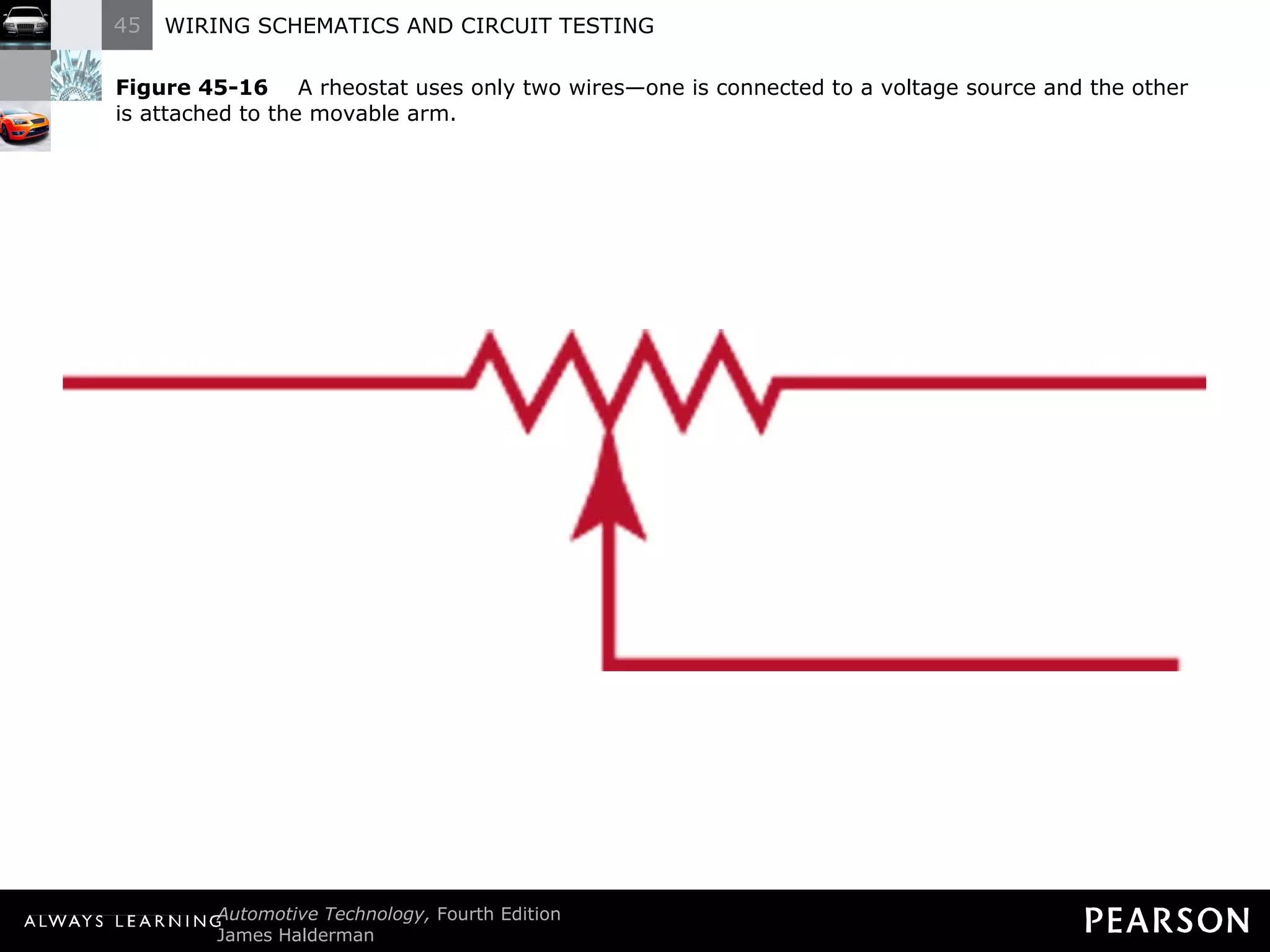
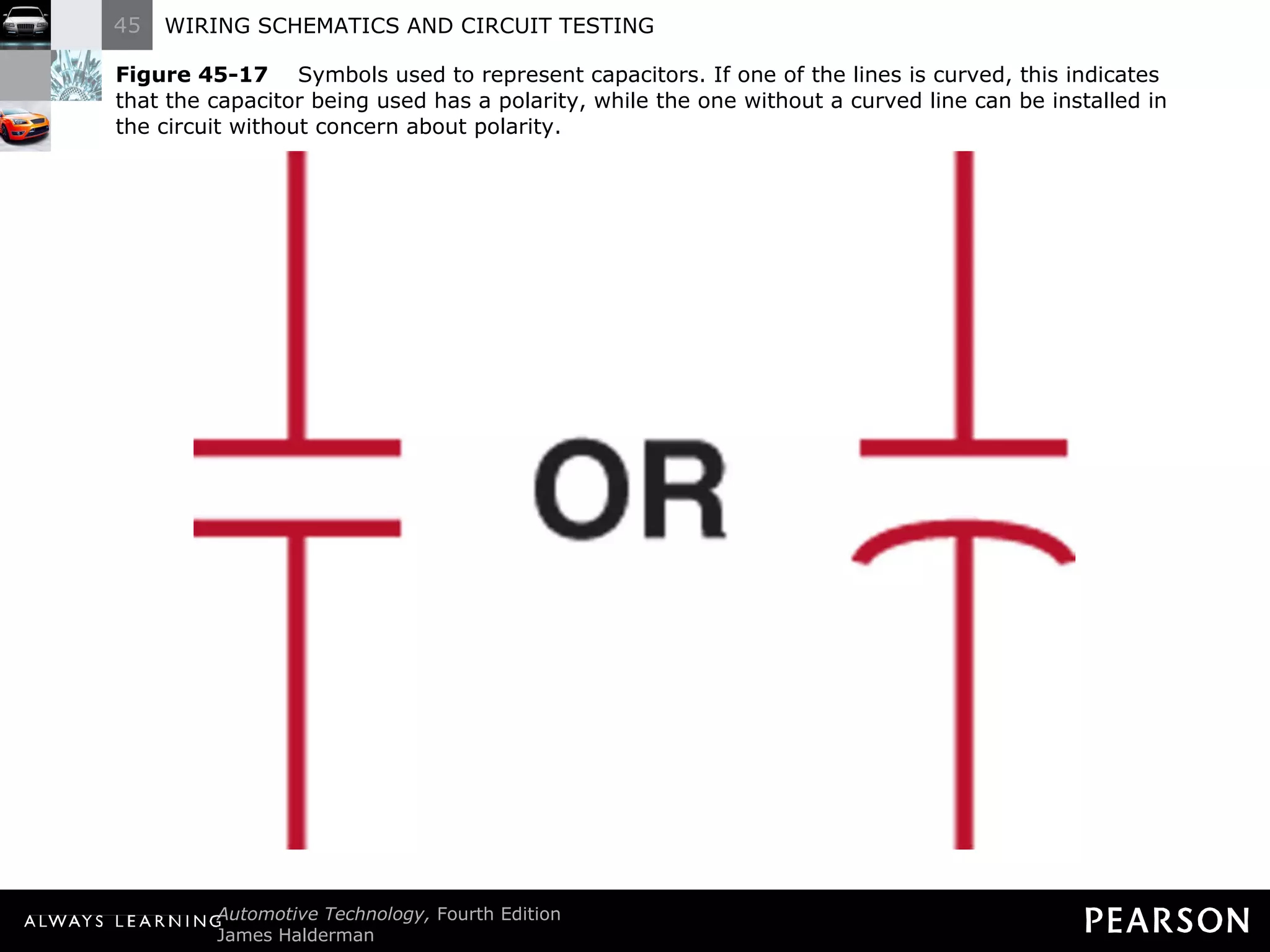
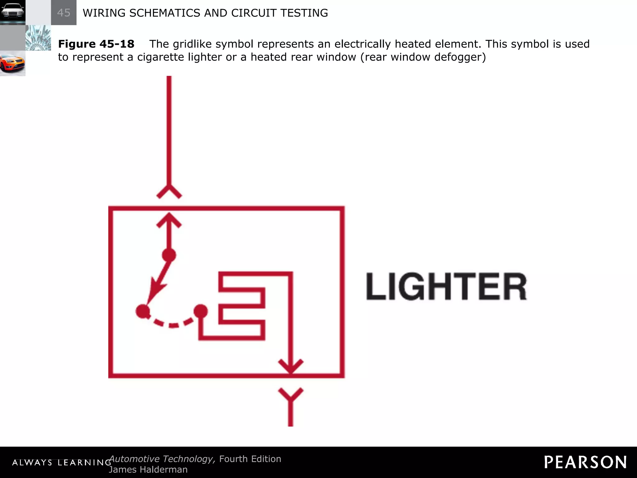
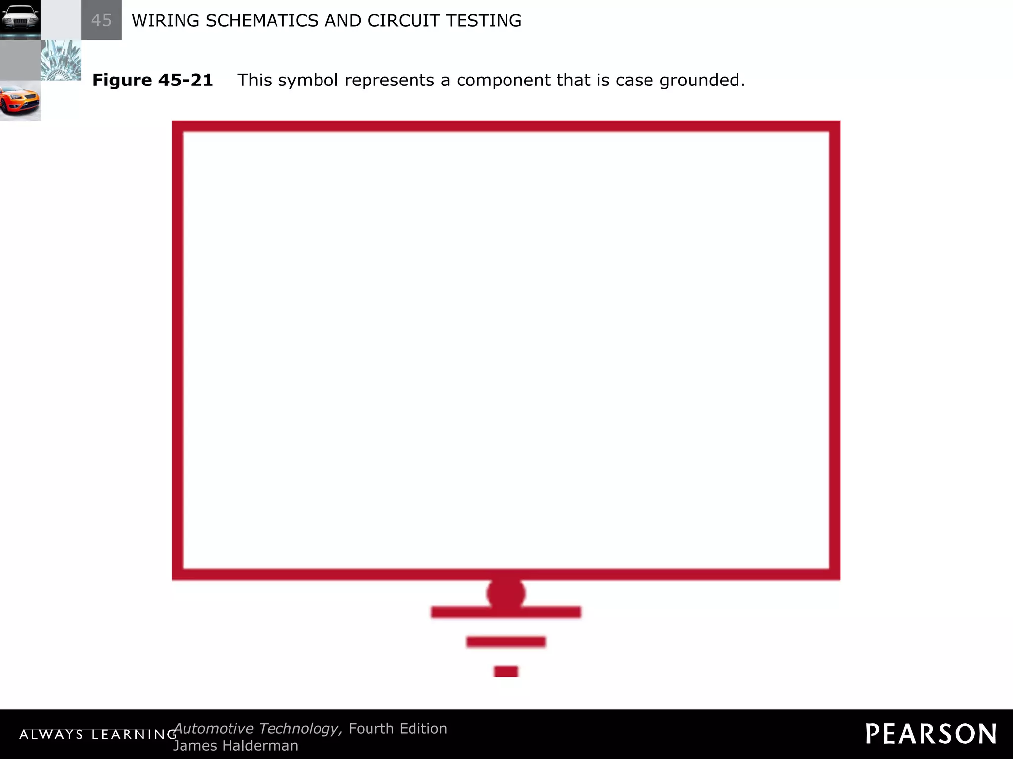
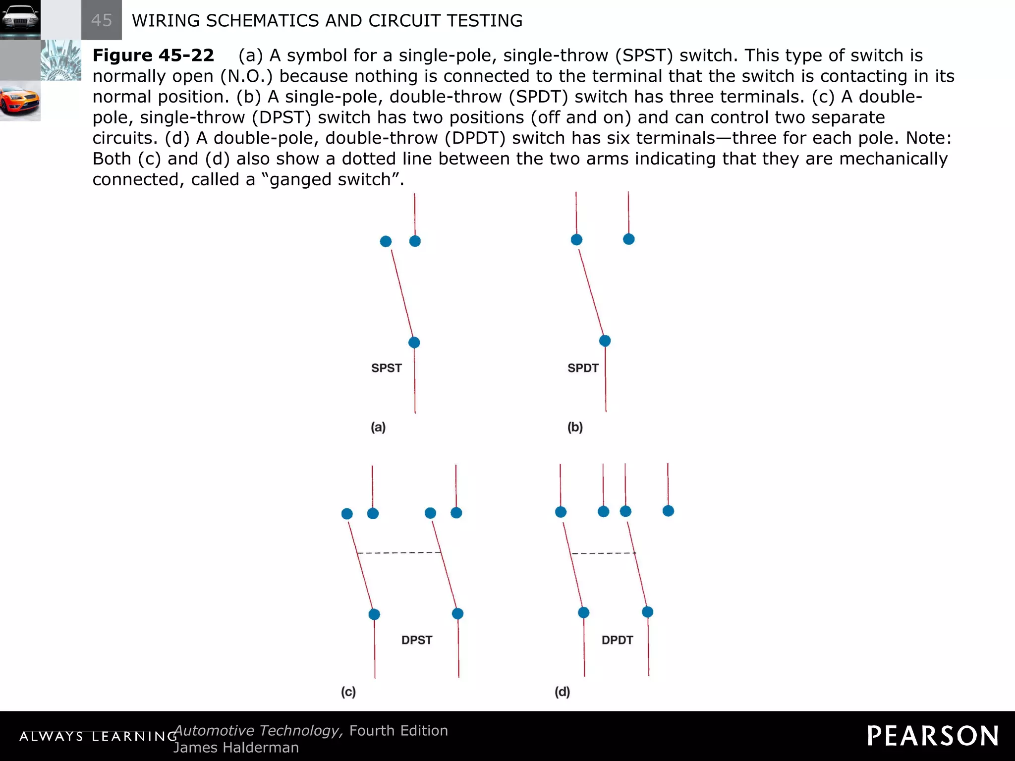
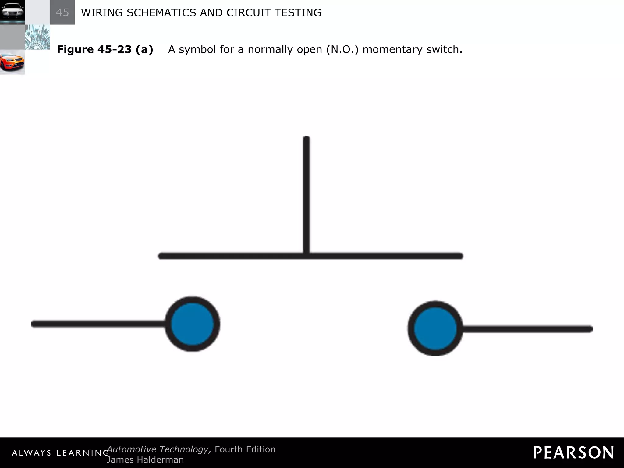
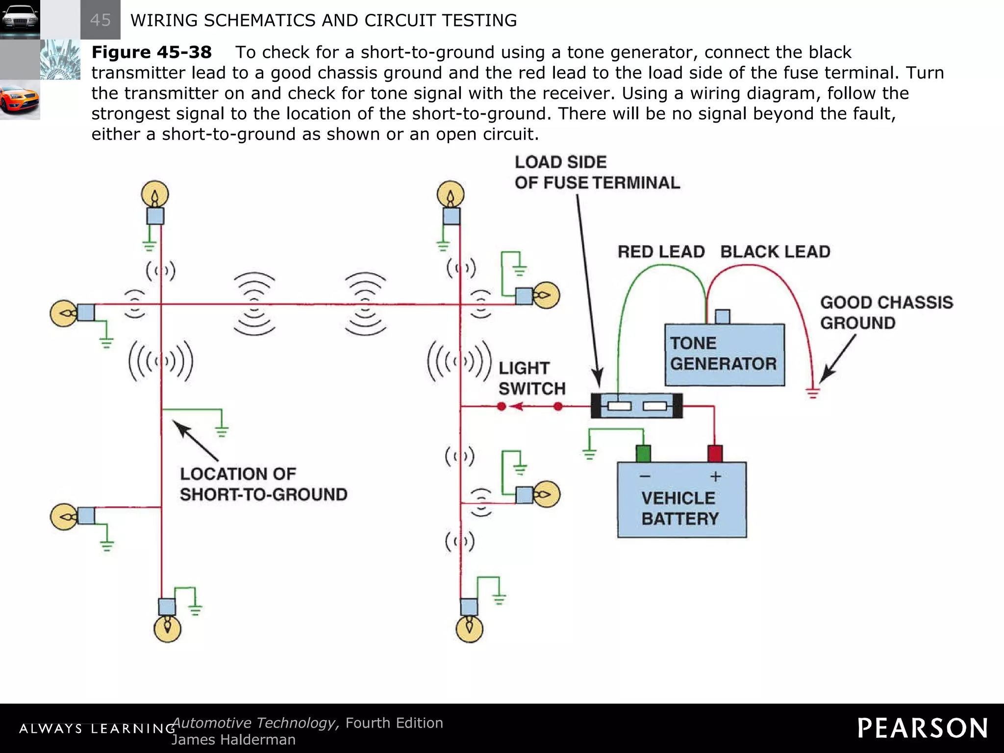
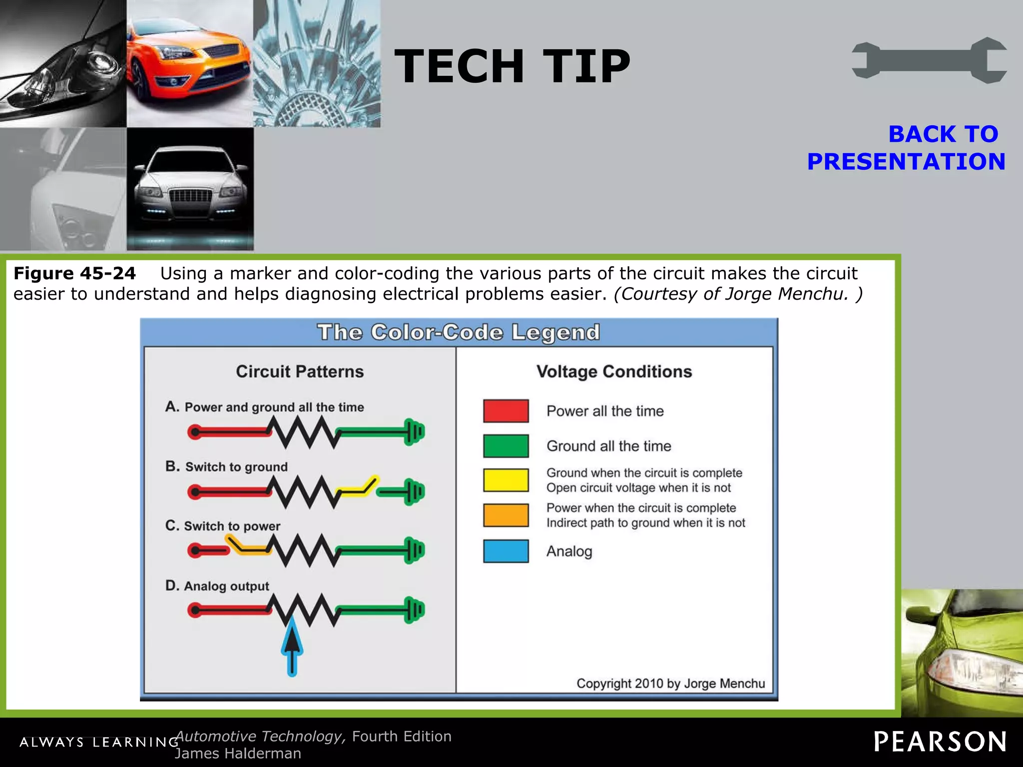
WIRING SCHEMATICS AND CIRCUIT TESTING 45
Objectives The student should be able to: Prepare for ASE Electrical/Electronic Systems (A6) certification test content area “A“ (General Electrical/Electronics System Diagnosis).  Interpret wiring schematics.  Explain how relays work.
Objectives The student should be able to: Discuss the various methods that can be used to locate a short circuit.  List the electrical troubleshooting diagnosis steps.
WIRING SCHEMATICS AND SYMBOLS
Wiring Schematics and Symbols Terminology A wiring schematic, sometimes called a diagram, uses symbols and lines to represent components and wires
Wiring Schematics and Symbols Terminology All circuit schematics or diagrams include: Power-side wiring of the circuit All splices
Wiring Schematics and Symbols Terminology All circuit schematics or diagrams include: Connectors Wire size
Wiring Schematics and Symbols Terminology All circuit schematics or diagrams include: Wire color Trace color (if any)
Wiring Schematics and Symbols Terminology All circuit schematics or diagrams include: Circuit number Electrical components
Wiring Schematics and Symbols Terminology All circuit schematics or diagrams include: Ground return paths Fuses and switches
Wiring Schematics and Symbols Circuit Information Most letters near or on a wire identify the color(s) of the wire The first color or color abbreviation is the color of the wire insulation
Wiring Schematics and Symbols Circuit Information The second color (if mentioned) is the color of the stripe or tracer on the base color
Wiring Schematics and Symbols Circuit Information Wires with different color tracers are indicated by both colors with a slash (/) between them
Figure 45-1   The center wire is a solid color wire, meaning that the wire has no other identifying tracer or stripe color. The two end wires could be labeled “BRN/WHT,” indicating a brown wire with a white tracer or stripe.
Chart 45-1  Typical abbreviations used on schematics to show wire color. Some vehicle manufacturers use two letters to represent a wire color. Check service information for the color abbreviations used.
Wiring Schematics and Symbols Wire Size Wire size is shown on all schematics
Figure 45-2   Typical section of a wiring diagram. Notice that the wire color changes at connection C210. The “.8” represents the metric wire size in square millimeters.
Figure 45-3   Typical electrical and electronic symbols used in automotive wiring and circuit diagrams.
SCHEMATIC SYMBOLS
Schematic Symbols  Photos or line drawings of actual components are replaced with a symbol Battery Plates of a battery are represented by long and short lines
Schematic Symbols  Battery Longer lines represent positive plates and shorter lines represent the negative plate
Schematic Symbols  Battery Each pair of short and long lines represents one cell of a battery
Schematic Symbols  Battery Most battery symbols use two or three pairs of long and short lines and then list the voltage of the battery next to the symbol
Schematic Symbols  Battery The positive terminal is often indicated with a plus sign (+) and is placed next to the long line of the end cell
Schematic Symbols  Battery The negative terminal is represented by a negative sign (−) and is placed next to the shorter cell line
Figure 45-5   The symbol for a battery. The positive plate of a battery is represented by the longer line and the negative plate by the shorter line. The voltage of the battery is usually stated next to the symbol.
Figure 45-6   The ground symbol on the left represents earth ground. The ground symbol on the right represents a chassis ground.
Schematic Symbols Wiring Electrical wiring is shown as straight lines with a few numbers and/or letters to indicate the following: Wire size Circuit numbers
Schematic Symbols Wiring Electrical wiring is shown as straight lines with a few numbers and/or letters to indicate the following: Wire color Terminals
Schematic Symbols Wiring Electrical wiring is shown as straight lines with a few numbers and/or letters to indicate the following: Splices Connectors
Schematic Symbols Wiring Electrical wiring is shown as straight lines with a few numbers and/or letters to indicate the following: Location Grounds and splices
Figure 45-7   Starting at the top, the wire from the ignition switch is attached to terminal B of connector C2, the wire is 0.5 mm 2  (20 gauge AWG), and is yellow. The circuit number is 5. The wire enters connector C202 at terminal B3.
Figure 45-8   The electrical terminals are usually labeled with a letter or number.
Figure 45-9   Two wires that cross at the dot indicate that the two are electrically connected.
Figure 45-10   Wires that cross, but do not electrically contact each other, are shown with one wire bridging over the other.
Figure 45-11   Connectors (C), grounds (G), and splices (S) are followed by a number, generally indicating the location in the vehicle. For example, G209 is a ground connection located under the dash.
Figure 45-12   The ground for the battery is labeled G305 indicating the ground connector is located in the passenger compartment of the vehicle. The ground wire is black (BLK), the circuit number is 50, and the wire is 32 mm 2  (2 gauge AWG).
Schematic Symbols Electrical Components Most electrical components have their own unique symbol A light bulb is represented by a circle with a filament inside A dual-filament bulb is shown with two filaments
Figure 45-13   The symbol for light bulbs shows the filament inside a circle, which represents the glass ampoule of the bulb.
Schematic Symbols Electric Motors Symbol is a circle with the letter M in the center and two electrical connections, one to the top and one at the bottom
Figure 45-14   An electric motor symbol shows a circle with the letter M in the center and two black sections that represent the brushes of the motor. This symbol is used even though the motor is a brushless design.
Schematic Symbols Resistors Symbol is a jagged line representing resistance to current flow If the resistor is variable an arrow is shown running through the symbol of a fixed resistor
Schematic Symbols Resistors A potentiometer is shown with an arrow pointing toward the resistance part of a fixed resistor
Figure 45-15   Resistor symbols vary depending on the type of resistor.
Figure 45-16   A rheostat uses only two wires—one is connected to a voltage source and the other is attached to the movable arm.
Schematic Symbols Capacitors Usually part of an electronic component, but not a replaceable component unless the vehicle is an older model
Figure 45-17   Symbols used to represent capacitors. If one of the lines is curved, this indicates that the capacitor being used has a polarity, while the one without a curved line can be installed in the circuit without concern about polarity.
Schematic Symbols Electric Heated Unit Electric grid-type rear window defoggers and cigarette lighters are shown with a square box-type symbol
Figure 45-18   The gridlike symbol represents an electrically heated element. This symbol is used to represent a cigarette lighter or a heated rear window (rear window defogger)
Schematic Symbols Boxed Components A component shown in a box using a solid line shows a box is the entire component If a box uses dashed lines, it represents part of a component
Figure 45-19   A dashed outline represents a portion (part) of a component.
Figure 45-20   A solid box represents an entire component.
Schematic Symbols Separate Replacement Part A schematic of General Motors vehicles shows the following: If a part name is underlined, it is a replaceable part
Schematic Symbols Separate Replacement Part A schematic of General Motors vehicles shows the following: If a part is not underlined, it is not available as a replaceable part, but is included with other components shown and sold as an assembly
Schematic Symbols Separate Replacement Part A schematic of General Motors vehicles shows the following: If the case itself is grounded, the ground symbol is attached to the component
Figure 45-21   This symbol represents a component that is case grounded.
Schematic Symbols Switches Electrical switches are drawn on a wiring diagram in their normal position. This can be one of two possible positions: Normally open Normally closed
Schematic Symbols Switches Poles refer to the number of circuits completed by the switch Throws refer to the number of output circuits
Schematic Symbols Switches Single-pole, single-throw (SPST) switches have only two positions (on or off)
Schematic Symbols Switches Single-pole, double-throw (SPDT) switches have three terminals, one wire in and two wires out
Schematic Symbols Switches NOTE: A SPDT switch is not an on or off type of switch but instead directs power from the source to either the high-beam lamps or the low-beam lamps.
Schematic Symbols Switches NOTE: All switches are shown on schematics in their normal position. This means that the headlight switch will be shown normally off, as are most other switches and controls.
Figure 45-22   (a) A symbol for a single-pole, single-throw (SPST) switch. This type of switch is normally open (N.O.) because nothing is connected to the terminal that the switch is contacting in its normal position. (b) A single-pole, double-throw (SPDT) switch has three terminals. (c) A double-pole, single-throw (DPST) switch has two positions (off and on) and can control two separate circuits. (d) A double-pole, double-throw (DPDT) switch has six terminals—three for each pole. Note: Both (c) and (d) also show a dotted line between the two arms indicating that they are mechanically connected, called a “ganged switch”.
Schematic Symbols  Momentary Switch Primarily used to send a voltage signal to a module or controller to request that a device be turned on or off
Schematic Symbols Momentary Switch The symbol uses two dots for the contact with a switch above them Momentary switches can be either normally open or normally closed
Schematic Symbols Momentary Switch A major advantage is that momentary switches can be lightweight and small
Schematic Symbols Momentary Switch Most momentary switches use a membrane constructed of foil and plastic
Figure 45-23 (a)   A symbol for a normally open (N.O.) momentary switch.
Figure 45-23 (b)   A symbol for a normally closed (N.C.) momentary switch.
RELAY TERMINAL IDENTIFICATION
Relay Terminal Identification Definition A relay is a magnetic switch that uses a movable armature to control a high-amperage circuit using a low-amperage electrical switch
Relay Terminal Identification ISO Relay Terminal Identification International Standards Organization (ISO) establishes standards for common identification of automotive relays
Figure 45-25   A relay uses a movable arm to complete a circuit whenever there is a power at terminal 86 and a ground at terminal 85. A typical relay only requires about 1/10 ampere through the relay coil. The movable arm then closes the contacts (#30 to #87) and can relay 30 amperes or more.
Figure 45-26   A cross-sectional view of a typical four-terminal relay. Current flowing through the coil (terminals 86 and 85) causes the movable arm (called the armature) to be drawn toward the coil magnet. The contact points complete the electrical circuit connected to terminals 30 and 87.
Relay Terminal Identification Relay Operation Coil (terminals 85 and 86) Provides magnetic pull to a movable arm
Relay Terminal Identification Relay Operation Coil (terminals 85 and 86) Resistance ranges from 50 to 150 ohms (usually between 60 and 100 ohms)
Relay Terminal Identification Relay Operation Coil (terminals 85 and 86) ISO identification of the terminals are 86 and 85 Terminal 86 represents power to the relay coil and terminal 85 represents the ground side of the coil
Relay Terminal Identification Relay Operation Coil (terminals 85 and 86) Relay coils can be controlled by supplying either power or ground to the relay coil winding Coil windings represent the control circuit
Relay Terminal Identification Relay Operation Other terminals used to control the load current Higher amperage current flows through terminals 30, 87, and often 87a
Relay Terminal Identification Relay Operation Other terminals used to control the load current In terminal 30 power is applied to a relay
Relay Terminal Identification Relay Operation Other terminals used to control the load current At rest, without power, and ground to the coil, the arm electrically connects terminals 30 and 87a if the relay has five terminals
Relay Terminal Identification Relay Operation Other terminals used to control the load current Power at terminal 85 and a ground at terminal 86 create a magnetic field in the coil winding drawing the arm toward the coil
Relay Terminal Identification Relay Operation Other terminals used to control the load current An electrically energized arm connects terminals 30 and 87
Figure 45-27   A typical relay showing the schematic of the wiring in the relay.
Figure 45-28   All schematics are shown in their normal, nonenergized position.
Figure 45-29   A typical horn circuit. Note that the relay contacts supply the heavy current to operate the horn when the horn switch simply completes a low-current circuit to ground, causing the relay contacts to close.
Relay Terminal Identification Relay Voltage Spike Control When there is no power, the magnetic field surrounding the coil collapses and creates a voltage as high as 100 volts or more
Relay Terminal Identification Relay Voltage Spike Control Voltage in the coil is applied in a forward direction through the diode, which conducts the current back into the winding eliminating the induced voltage spike
Figure 45-30   When the relay or solenoid coil current is turned off, the stored energy in the coil flows through the clamping diode and effectively reduces voltage spike.
Figure 45-31   A resistor used in parallel with the coil windings is a common spike reduction method used in many relays.
LOCATING AN OPEN CIRCUIT
Locating an Open Circuit Terminology An open circuit is a break in the electrical circuit preventing current from flowing
Locating an Open Circuit Terminology Examples include: Blown (open) light bulbs Cut or broken wires
Locating an Open Circuit Terminology Examples include: Disconnected or partially disconnected electrical connectors Electrically open switches
Locating an Open Circuit Terminology Examples include: Loose or broken ground connections or wires Blown fuse
Locating an Open Circuit Procedure to Locate and Open Circuit STEP 1: Perform a thorough visual inspection check for the following: Evidence of a previous repair (an electrical connector or ground connection can be accidentally left disconnected).
Locating an Open Circuit Procedure to Locate and Open Circuit STEP 1: Perform a thorough visual inspection check for the following: Evidence of recent body damage or body repairs (collisions can cause metal to move and cut wires or damage connectors or components).
Locating an Open Circuit Procedure to Locate and Open Circuit STEP 2: Print out the schematic. Trace the circuit and check for voltage at certain places to pinpoint the location of the open circuit.
Locating an Open Circuit Procedure to Locate and Open Circuit STEP 3: Check everything that does and does not work. Check the part of the circuit that is common to the other components that do not work.
Locating an Open Circuit Procedure to Locate and Open Circuit STEP 4: Check for voltage. Voltage is present up to the location of the open circuit fault.
COMMON POWER OR GROUND
Common Power or Ground To diagnose an electrical problem affecting multiple components check the electrical schematic for a common power source or ground
Common Power or Ground Examples of lights being powered by one fuse: Underhood light Inside lighted mirrors
Common Power or Ground Examples of lights being powered by one fuse: Dome light Left-side courtesy light Right-side courtesy light
Common Power or Ground If one or more of the listed items are faulty, check the fuse and common part of the circuit that feeds all of the affected lights. Check for a common ground if several components that seem unrelated are not functioning correctly. ?
Figure 45-32   A typical wiring diagram showing multiple switches and bulbs powered by one fuse.
Figure 45-33   To add additional lighting, simply tap into an existing light wire and connect a relay. Whenever the existing light is turned on, the coil of the relay is energized. The arm of the relay then connects power from another circuit (fuse) to the auxiliary lights without overloading the existing light circuit.
CIRCUIT TROUBLESHOOTING PROCEDURE
Circuit Troubleshooting Procedure STEP 1: Verify the malfunction. STEP 2: Check everything else that does or does not operate correctly. STEP 3: Check the fuse for the backup lights.
Circuit Troubleshooting Procedure STEP 4: Check for voltage at the backup light socket using a test light or voltmeter.
Circuit Troubleshooting Procedure If voltage is available, the problem is a defective bulb, a poor ground at the socket, or a ground wire connection to the body or frame
Circuit Troubleshooting Procedure If no voltage is available, consult a wiring diagram for the type of vehicle being tested
Figure 45-34   Always check the simple things first. Check the fuse for the circuit you are testing. Maybe a fault in another circuit controlled by the same fuse could have caused the fuse to blow. Use a test light to check that both sides of the fuse have voltage.
LOCATING  A SHORT CIRCUIT
Locating a Short Circuit  Terminology A short circuit is an electrical connection to another wire or to ground before the current flows through some or all of the resistance in the circuit
Locating a Short Circuit  Terminology A short-to-ground will always blow a fuse  A short-to-ground usually involves a wire on the power side of the circuit coming in contact with metal
Locating a Short Circuit  Terminology A thorough visual inspection should be performed around areas involving heat or movement A short-to-voltage may or may not cause the fuse to blow
Locating a Short Circuit  Terminology A short-to-voltage usually affects another circuit  Look for areas of heat or movement where two power wires could come in contact ?
Locating a Short Circuit Fuse Replacement Method Disconnect one component at a time and then replace the fuse If the new fuse blows, continue the process until you find the short location Not a preferred method
Locating a Short Circuit Circuit Breaker Method Connect an automotive circuit breaker to the contacts of the fuse holder with alligator clips
Locating a Short Circuit Circuit Breaker Method Disconnect all components in the defective circuit one at a time until the circuit breaker stops clicking
Locating a Short Circuit Circuit Breaker Method The unit that stopped the circuit breaker clicking is the one causing the short circuit
Locating a Short Circuit Circuit Breaker Method If the circuit breaker continues after all components are unplugged, the problem is in the wiring from the fuse panel to any one of the units in the circuit
Locating a Short Circuit Circuit Breaker Method NOTE: A heavy-duty (HD) flasher can also be used in place of a circuit breaker to open and close the circuit. Wires and terminals must be made to connect the flasher unit where the fuse normally plugs in.
Locating a Short Circuit Test Light Method Remove the blown fuse and connect a test light to the terminals of the fuse holder (polarity does not matter)
Locating a Short Circuit Test Light Method If there is a short circuit, the test light will go on Unplug the connectors or components protected by the fuse until the test light goes out
Locating a Short Circuit Test Light Method The circuit that was disconnected, which caused the test light to go out, is the shorted circuit
Locating a Short Circuit Buzzer Method Similar to the test light method Uses a buzzer to replace a fuse and act as an electrical load
Locating a Short Circuit Buzzer Method Buzzer will sound if the circuit is shorted and will stop when the part of the circuit that is grounded is unplugged
Locating a Short Circuit Ohmmeter Method An ohmmeter is connected to the fuse holder and ground Recommended method of finding a short circuit Never connect an ohmmeter to an operating circuit
Locating a Short Circuit Ohmmeter Method The correct procedure for locating a short using an ohmmeter is as follows: Connect one lead of an ohmmeter (set to a low scale) to a good clean metal ground and the other lead to the circuit (load) side of the fuse holder.
Locating a Short Circuit Ohmmeter Method The correct procedure for locating a short using an ohmmeter is as follows: The ohmmeter will read zero or almost zero ohms if the circuit or a component in the circuit is shorted.
Locating a Short Circuit Ohmmeter Method The correct procedure for locating a short using an ohmmeter is as follows: Disconnect one component in the circuit at a time and watch the ohmmeter. If the ohmmeter reading goes to high ohms or infinity, the component just unplugged was the source of the short circuit.
Locating a Short Circuit Ohmmeter Method The correct procedure for locating a short using an ohmmeter is as follows: If all of the components have been disconnected and the ohmmeter still reads low ohms, then disconnect electrical connectors until the ohmmeter reads high ohms. The location of the short to ground is then between the ohmmeter and the disconnected connector.
Locating a Short Circuit Ohmmeter Method CAUTION: Connecting the lead to the power side of the fuse holder will cause current flow through and damage to the ohmmeter.
Locating a Short Circuit Ohmmeter Method NOTE: Some meters, such as the Fluke 87, can be set to beep (alert) when the circuit closes or when the circuit opens—a very useful feature.
Locating a Short Circuit Gauss Gauge Method A pulsing circuit breaker (similar to a flasher unit) can be installed in the circuit in place of the fuse Current will flow through the circuit until the circuit breaker opens it
Locating a Short Circuit Gauss Gauge Method As soon as the circuit breaker opens the circuit, it closes again creating a pulsing magnetic field around the wire carrying the current
Locating a Short Circuit Gauss Gauge Method A Gauss gauge is a handheld meter that responds to weak magnetic fields and is used to observe this pulsing magnetic field
Figure 45-35 (a)   After removing the blown fuse, a pulsing circuit breaker is connected to the terminals of the fuse.
Figure 45-35 (b)   The circuit breaker causes current to flow, then stop, then flow again, through the circuit up to the point of the short-to-ground. By observing the Gauss gauge, the location of the short is indicated near where the needle stops moving due to the magnetic field created by the flow of current through the wire.
Figure 45-36   A Gauss gauge can be used to determine the location of a short circuit even behind a metal panel.
Locating a Short Circuit Electronic Tone Generator Test Used to locate a short-to-ground or an open circuit A tone generator tester generates a tone that can be heard through a receiver (probe)
Locating a Short Circuit Electronic Tone Generator Test The tone is generated as long as there is a continuous electrical path along the circuit
Locating a Short Circuit Electronic Tone Generator Test The signal will stop if there is a short-to-ground or an open in the circuit
Figure 45-37   A tone generator-type tester used to locate open circuits and circuits that are shorted-to-ground. Included with this tester is a transmitter (tone generator), receiver probe, and headphones for use in noisy shops.
Figure 45-38   To check for a short-to-ground using a tone generator, connect the black transmitter lead to a good chassis ground and the red lead to the load side of the fuse terminal. Turn the transmitter on and check for tone signal with the receiver. Using a wiring diagram, follow the strongest signal to the location of the short-to-ground. There will be no signal beyond the fault, either a short-to-ground as shown or an open circuit.
ELECTRICAL TROUBLESHOOTING GUIDE
Electrical Troubleshooting Guide Remember the following hints to find the problem faster and more easily. For a device to work, it must have two things: power and ground. If there is no power to a device, an open power side (blown fuse, etc.) is indicated.
Electrical Troubleshooting Guide Remember the following hints to find the problem faster and more easily. If there is power on both sides of a device, an open ground is indicated.
Electrical Troubleshooting Guide Remember the following hints to find the problem faster and more easily. If a fuse blows immediately, a grounded power-side wire is indicated.
Electrical Troubleshooting Guide Remember the following hints to find the problem faster and more easily. Most electrical faults result from heat or movement. Most noncomputer-controlled devices operate by opening and closing the power side of the circuit (power-side switch).
Electrical Troubleshooting Guide Remember the following hints to find the problem faster and more easily. Most computer-controlled devices operate by opening and closing the ground side of the circuit (ground-side switch).
STEP-BY-STEP TROUBLESHOOTING PROCEDURE
Step-By-Step Troubleshooting Procedure The following procedure provides a step-by-step guide for troubleshooting an electrical fault. STEP 1: Determine the customer concern (complaint) and get as much information as possible from the customer or service advisor. When did the problem start?
Step-By-Step Troubleshooting Procedure The following procedure provides a step-by-step guide for troubleshooting an electrical fault. STEP 1: Determine the customer concern (complaint) and get as much information as possible from the customer or service advisor. Under what conditions does the problem occur?
Step-By-Step Troubleshooting Procedure The following procedure provides a step-by-step guide for troubleshooting an electrical fault. STEP 1: Determine the customer concern (complaint) and get as much information as possible from the customer or service advisor. Have there been any recent previous repairs to the vehicle?
Step-By-Step Troubleshooting Procedure The following procedure provides a step-by-step guide for troubleshooting an electrical fault. STEP 2: Verify the customer’s concern by actually observing the fault.
Step-By-Step Troubleshooting Procedure The following procedure provides a step-by-step guide for troubleshooting an electrical fault. STEP 3: Perform a thorough visual inspection and be sure to check everything that does and does not work.
Step-By-Step Troubleshooting Procedure The following procedure provides a step-by-step guide for troubleshooting an electrical fault. STEP 4: Check for technical service bulletins (TSBs). STEP 5: Locate the wiring schematic for the circuit being diagnosed.
Step-By-Step Troubleshooting Procedure The following procedure provides a step-by-step guide for troubleshooting an electrical fault. STEP 6: Check the factory service information and follow the troubleshooting procedure. Determine how the circuit works.
Step-By-Step Troubleshooting Procedure The following procedure provides a step-by-step guide for troubleshooting an electrical fault. STEP 6: Check the factory service information and follow the troubleshooting procedure. Determine which part of the circuit is good, based on what works and what does not work.
Step-By-Step Troubleshooting Procedure The following procedure provides a step-by-step guide for troubleshooting an electrical fault. STEP 6: Check the factory service information and follow the troubleshooting procedure. Isolate the problem area.
Step-By-Step Troubleshooting Procedure The following procedure provides a step-by-step guide for troubleshooting an electrical fault. STEP 7: Determine the root cause and repair the vehicle.
Step-By-Step Troubleshooting Procedure The following procedure provides a step-by-step guide for troubleshooting an electrical fault. STEP 8: Verify the repair and complete the work order by listing the three Cs (complaint, cause, and correction).
Step-By-Step Troubleshooting Procedure NOTE: Split the circuit in half to help isolate the problem and start at the relay (if the circuit has a relay).
TECH TIP Read the Arrows Wiring diagrams indicate connections by symbols that look like arrows. Do  not  read these “arrows” as pointers showing the direction of current flow. Also observe that the power side (positive side) of the circuit is usually the female end of the connector. If a connector becomes disconnected, it will be difficult for the circuit to become shorted to ground or to another circuit because the wire is recessed inside the connector. BACK TO  PRESENTATION Figure 45-4   In this typical connector, note that the positive terminal is usually a female connector.
TECH TIP Color-Coding Is Key to Understanding Whenever diagnosing an electrical problem, it is common practice to print out the schematic of the circuit and then take it to the vehicle. A meter is then used to check for voltage at various parts of the circuit to help determine where there is a fault. BACK TO  PRESENTATION The diagnosis can be made easier if the parts of the circuit are first color coded using markers or color pencils. A color-coding system that has been widely used is one developed by Jorge Menchu ( www.aeswave.com ). The colors represent voltage conditions in various parts of a circuit. Once the circuit has been color coded, then the circuit can be tested using the factory wire colors as a guide. Figure 45-24   Using a marker and color-coding the various parts of the circuit makes the circuit easier to understand and helps diagnosing electrical problems easier.  (Courtesy of Jorge Menchu. )
TECH TIP Divide the Circuit in Half When diagnosing any circuit that has a relay, start testing at the relay and divide the circuit in half. High current portion: Remove the relay and check that there are 12 volts at the terminal 30 socket. If there is, then the power side is okay. BACK TO  PRESENTATION Use an ohmmeter and check between terminal 87 socket and ground. If the load circuit has continuity, there should be some resistance. If OL, the circuit is electrically open. Control circuit (low current): With the relay removed from the socket, check that there is 12 volts to terminal 86 with the ignition on and the control switch on. If not, check service information to see if power should be applied to terminal 86, then continue troubleshooting the switch power and related circuit. Check the relay itself: Use an ohmmeter and measure for continuity and resistance. Between terminals 85 and 86 (coil), there should be 60 to 100 ohms. If not, replace the relay. Between terminals 30 and 87 (high-amperage switch controls), there should be continuity (low ohms) when there is power applied to terminal 85 and a ground applied to terminal 86 that operates the relay. If OL is displayed on the meter set to read  ohms, the circuit is open which requires that  the reply be replaced. Between terminals 30 and 87a (if equipped), with the relay turned off, there should be low resistance (less than 5 ohms).
FREQUENTLY ASKED QUESTION What Is the Difference Between a Relay and a Solenoid? Often, these terms are used differently among vehicle manufacturers, which can lead to some confusion. ? Relay: A relay is an electromagnetic switch that uses a movable arm. Because a relay uses a movable arm, it is generally limited to current flow not exceeding 30 amperes.  Solenoid: A solenoid is an electromagnetic switch that uses a movable core. Because of this type of design, a solenoid is capable of handling 200 amperes or more and is used in the starter motor circuit and other high-amperage applications, such as in the glow plug circuit of diesel engines. BACK TO  PRESENTATION
REAL WORLD FIX The Electric Mirror Fault Story Often, a customer will notice just one fault even though other lights or systems may not be working correctly. For example, a customer noticed that the electric mirrors stopped working. The service technician checked all electrical components in the vehicle and discovered that the interior lights were also not working. The interior lights were not mentioned by the customer as being a problem most likely  because the driver only used the vehicle in  daylight hours. The service technician found the interior light and power accessory fuse blown. Replacing the fuse restored the proper operation of the  electric outside mirror and the interior lights. However, what caused the fuse to blow? A visual inspection of the dome light, next to the electric sunroof, showed an area where a wire was bare. Evidence showed the bare wire had touched the metal roof, which could cause the fuse to blow. The technician covered the bare wire with a section of vacuum hose and then taped the hose with electrical tape to complete the repair. BACK TO  PRESENTATION
TECH TIP Do It Right—Install a Relay Often the owners of vehicles, especially owners of pickup trucks and sport utility vehicles (SUVs), want to add additional electrical accessories or lighting. It is tempting in these cases to simply splice into an existing circuit. However, when another circuit or component is added, the current that flows through the newly added component is also added to the current for the original component. This additional current can easily overload the fuse and wiring. Do not simply install a larger amperage fuse; the wire gauge size was not engineered for the additional current and could overheat.  The solution is to install a relay, which uses a small coil to create a magnetic field that causes a movable arm to switch on a higher current circuit. The typical relay coil has from 50 to 150 ohms (usually 60 to 100 ohms) of resistance and requires just 0.24 to 0.08 ampere when connected to a 12 volt source. This small additional current will not be enough to overload the existing circuit. BACK TO  PRESENTATION Figure 45-33   To add additional lighting, simply tap into an existing light wire and connect a relay. Whenever the existing light is turned on, the coil of the relay is energized. The arm of the relay then connects power from another circuit (fuse) to the auxiliary lights without overloading the existing light circuit.
FREQUENTLY ASKED QUESTION Where to Start? The common question is, where does a technician start the troubleshooting when using a wiring diagram (schematic)? HINT 1 If the circuit contains a relay, start your diagnosis at the relay. The entire circuit can be tested at the terminals of the relay. ? BACK TO  PRESENTATION Often a ground is used by more than one component. Therefore, ensure that everything else is working correctly. If not, then the fault may lie at the common ground (or power) connection. HINT 2 - The easiest first step is to locate the unit on the schematic that is not working at all or not working correctly. Trace where the unit gets its ground connection. Trace where the unit gets its power  connection. HINT 3 - Divide the circuit in half by locating a connector or a part of the circuit that can be accessed easily. Then check for power and ground at this midpoint. This step could save you much time. HINT 4 - Use a fused jumper wire to substitute a ground or a power source to replace a suspected switch or section of wire.
TECH TIP Heat or Movement Electrical shorts are commonly caused either by movement, which causes the insulation around the wiring to be worn away, or by heat melting the insulation. When checking for a short circuit, first check the wiring that is susceptible to heat, movement, and damage. BACK TO  PRESENTATION Heat. Wiring near heat sources, such as the exhaust system, cigarette lighter, or alternator Wire movement. Wiring that moves, such as in areas near the doors, trunk, or hood Damage. Wiring subject to mechanical injury, such as in the trunk, where heavy objects can move around and smash or damage wiring, can also occur as a result of an accident or previous repair.
TECH TIP Wiggle Test Intermittent electrical problems are common yet difficult to locate. To help locate these hard-to-find problems, try operating the circuit and then start wiggling the wires and connections that control the circuit. If in doubt where the wiring goes, try moving all the wiring starting at the battery.  Pay particular attention to wiring running near the battery or the windshield washer container. Corrosion can cause wiring to fail, and battery acid fumes and alcohol-based windshield washer fluid can start or contribute to the problem. If you notice any change in the operation of the device being tested while wiggling the wiring, look closer in the area you were wiggling until you locate and correct the actual problem. BACK TO  PRESENTATION
REAL WORLD FIX Shocking Experience A customer complained that after driving for a while, he got a static shock whenever he grabbed the door handle when exiting the vehicle. The customer thought that there must be an electrical fault and that the shock was coming from the vehicle itself. BACK TO  PRESENTATION In a way, the shock was caused by the vehicle, but it was not a fault. The service technician sprayed the cloth seats with an antistatic spray and the problem did not reoccur. Obviously, a static charge was being created by the movement of the driver’s clothing on the seats and then discharged when the driver touched the metal door handle. Figure 45-39   Antistatic spray can be used by customers to prevent being shocked when they touch a metal object like the door handle.

Halderman ch045 lecture

  • 1.
    WIRING SCHEMATICS ANDCIRCUIT TESTING 45
  • 2.
    Objectives The studentshould be able to: Prepare for ASE Electrical/Electronic Systems (A6) certification test content area “A“ (General Electrical/Electronics System Diagnosis). Interpret wiring schematics. Explain how relays work.
  • 3.
    Objectives The studentshould be able to: Discuss the various methods that can be used to locate a short circuit. List the electrical troubleshooting diagnosis steps.
  • 4.
  • 5.
    Wiring Schematics andSymbols Terminology A wiring schematic, sometimes called a diagram, uses symbols and lines to represent components and wires
  • 6.
    Wiring Schematics andSymbols Terminology All circuit schematics or diagrams include: Power-side wiring of the circuit All splices
  • 7.
    Wiring Schematics andSymbols Terminology All circuit schematics or diagrams include: Connectors Wire size
  • 8.
    Wiring Schematics andSymbols Terminology All circuit schematics or diagrams include: Wire color Trace color (if any)
  • 9.
    Wiring Schematics andSymbols Terminology All circuit schematics or diagrams include: Circuit number Electrical components
  • 10.
    Wiring Schematics andSymbols Terminology All circuit schematics or diagrams include: Ground return paths Fuses and switches
  • 11.
    Wiring Schematics andSymbols Circuit Information Most letters near or on a wire identify the color(s) of the wire The first color or color abbreviation is the color of the wire insulation
  • 12.
    Wiring Schematics andSymbols Circuit Information The second color (if mentioned) is the color of the stripe or tracer on the base color
  • 13.
    Wiring Schematics andSymbols Circuit Information Wires with different color tracers are indicated by both colors with a slash (/) between them
  • 14.
    Figure 45-1 The center wire is a solid color wire, meaning that the wire has no other identifying tracer or stripe color. The two end wires could be labeled “BRN/WHT,” indicating a brown wire with a white tracer or stripe.
  • 15.
    Chart 45-1 Typical abbreviations used on schematics to show wire color. Some vehicle manufacturers use two letters to represent a wire color. Check service information for the color abbreviations used.
  • 16.
    Wiring Schematics andSymbols Wire Size Wire size is shown on all schematics
  • 17.
    Figure 45-2 Typical section of a wiring diagram. Notice that the wire color changes at connection C210. The “.8” represents the metric wire size in square millimeters.
  • 18.
    Figure 45-3 Typical electrical and electronic symbols used in automotive wiring and circuit diagrams.
  • 19.
  • 20.
    Schematic Symbols Photos or line drawings of actual components are replaced with a symbol Battery Plates of a battery are represented by long and short lines
  • 21.
    Schematic Symbols Battery Longer lines represent positive plates and shorter lines represent the negative plate
  • 22.
    Schematic Symbols Battery Each pair of short and long lines represents one cell of a battery
  • 23.
    Schematic Symbols Battery Most battery symbols use two or three pairs of long and short lines and then list the voltage of the battery next to the symbol
  • 24.
    Schematic Symbols Battery The positive terminal is often indicated with a plus sign (+) and is placed next to the long line of the end cell
  • 25.
    Schematic Symbols Battery The negative terminal is represented by a negative sign (−) and is placed next to the shorter cell line
  • 26.
    Figure 45-5 The symbol for a battery. The positive plate of a battery is represented by the longer line and the negative plate by the shorter line. The voltage of the battery is usually stated next to the symbol.
  • 27.
    Figure 45-6 The ground symbol on the left represents earth ground. The ground symbol on the right represents a chassis ground.
  • 28.
    Schematic Symbols WiringElectrical wiring is shown as straight lines with a few numbers and/or letters to indicate the following: Wire size Circuit numbers
  • 29.
    Schematic Symbols WiringElectrical wiring is shown as straight lines with a few numbers and/or letters to indicate the following: Wire color Terminals
  • 30.
    Schematic Symbols WiringElectrical wiring is shown as straight lines with a few numbers and/or letters to indicate the following: Splices Connectors
  • 31.
    Schematic Symbols WiringElectrical wiring is shown as straight lines with a few numbers and/or letters to indicate the following: Location Grounds and splices
  • 32.
    Figure 45-7 Starting at the top, the wire from the ignition switch is attached to terminal B of connector C2, the wire is 0.5 mm 2 (20 gauge AWG), and is yellow. The circuit number is 5. The wire enters connector C202 at terminal B3.
  • 33.
    Figure 45-8 The electrical terminals are usually labeled with a letter or number.
  • 34.
    Figure 45-9 Two wires that cross at the dot indicate that the two are electrically connected.
  • 35.
    Figure 45-10 Wires that cross, but do not electrically contact each other, are shown with one wire bridging over the other.
  • 36.
    Figure 45-11 Connectors (C), grounds (G), and splices (S) are followed by a number, generally indicating the location in the vehicle. For example, G209 is a ground connection located under the dash.
  • 37.
    Figure 45-12 The ground for the battery is labeled G305 indicating the ground connector is located in the passenger compartment of the vehicle. The ground wire is black (BLK), the circuit number is 50, and the wire is 32 mm 2 (2 gauge AWG).
  • 38.
    Schematic Symbols ElectricalComponents Most electrical components have their own unique symbol A light bulb is represented by a circle with a filament inside A dual-filament bulb is shown with two filaments
  • 39.
    Figure 45-13 The symbol for light bulbs shows the filament inside a circle, which represents the glass ampoule of the bulb.
  • 40.
    Schematic Symbols ElectricMotors Symbol is a circle with the letter M in the center and two electrical connections, one to the top and one at the bottom
  • 41.
    Figure 45-14 An electric motor symbol shows a circle with the letter M in the center and two black sections that represent the brushes of the motor. This symbol is used even though the motor is a brushless design.
  • 42.
    Schematic Symbols ResistorsSymbol is a jagged line representing resistance to current flow If the resistor is variable an arrow is shown running through the symbol of a fixed resistor
  • 43.
    Schematic Symbols ResistorsA potentiometer is shown with an arrow pointing toward the resistance part of a fixed resistor
  • 44.
    Figure 45-15 Resistor symbols vary depending on the type of resistor.
  • 45.
    Figure 45-16 A rheostat uses only two wires—one is connected to a voltage source and the other is attached to the movable arm.
  • 46.
    Schematic Symbols CapacitorsUsually part of an electronic component, but not a replaceable component unless the vehicle is an older model
  • 47.
    Figure 45-17 Symbols used to represent capacitors. If one of the lines is curved, this indicates that the capacitor being used has a polarity, while the one without a curved line can be installed in the circuit without concern about polarity.
  • 48.
    Schematic Symbols ElectricHeated Unit Electric grid-type rear window defoggers and cigarette lighters are shown with a square box-type symbol
  • 49.
    Figure 45-18 The gridlike symbol represents an electrically heated element. This symbol is used to represent a cigarette lighter or a heated rear window (rear window defogger)
  • 50.
    Schematic Symbols BoxedComponents A component shown in a box using a solid line shows a box is the entire component If a box uses dashed lines, it represents part of a component
  • 51.
    Figure 45-19 A dashed outline represents a portion (part) of a component.
  • 52.
    Figure 45-20 A solid box represents an entire component.
  • 53.
    Schematic Symbols SeparateReplacement Part A schematic of General Motors vehicles shows the following: If a part name is underlined, it is a replaceable part
  • 54.
    Schematic Symbols SeparateReplacement Part A schematic of General Motors vehicles shows the following: If a part is not underlined, it is not available as a replaceable part, but is included with other components shown and sold as an assembly
  • 55.
    Schematic Symbols SeparateReplacement Part A schematic of General Motors vehicles shows the following: If the case itself is grounded, the ground symbol is attached to the component
  • 56.
    Figure 45-21 This symbol represents a component that is case grounded.
  • 57.
    Schematic Symbols SwitchesElectrical switches are drawn on a wiring diagram in their normal position. This can be one of two possible positions: Normally open Normally closed
  • 58.
    Schematic Symbols SwitchesPoles refer to the number of circuits completed by the switch Throws refer to the number of output circuits
  • 59.
    Schematic Symbols SwitchesSingle-pole, single-throw (SPST) switches have only two positions (on or off)
  • 60.
    Schematic Symbols SwitchesSingle-pole, double-throw (SPDT) switches have three terminals, one wire in and two wires out
  • 61.
    Schematic Symbols SwitchesNOTE: A SPDT switch is not an on or off type of switch but instead directs power from the source to either the high-beam lamps or the low-beam lamps.
  • 62.
    Schematic Symbols SwitchesNOTE: All switches are shown on schematics in their normal position. This means that the headlight switch will be shown normally off, as are most other switches and controls.
  • 63.
    Figure 45-22 (a) A symbol for a single-pole, single-throw (SPST) switch. This type of switch is normally open (N.O.) because nothing is connected to the terminal that the switch is contacting in its normal position. (b) A single-pole, double-throw (SPDT) switch has three terminals. (c) A double-pole, single-throw (DPST) switch has two positions (off and on) and can control two separate circuits. (d) A double-pole, double-throw (DPDT) switch has six terminals—three for each pole. Note: Both (c) and (d) also show a dotted line between the two arms indicating that they are mechanically connected, called a “ganged switch”.
  • 64.
    Schematic Symbols Momentary Switch Primarily used to send a voltage signal to a module or controller to request that a device be turned on or off
  • 65.
    Schematic Symbols MomentarySwitch The symbol uses two dots for the contact with a switch above them Momentary switches can be either normally open or normally closed
  • 66.
    Schematic Symbols MomentarySwitch A major advantage is that momentary switches can be lightweight and small
  • 67.
    Schematic Symbols MomentarySwitch Most momentary switches use a membrane constructed of foil and plastic
  • 68.
    Figure 45-23 (a) A symbol for a normally open (N.O.) momentary switch.
  • 69.
    Figure 45-23 (b) A symbol for a normally closed (N.C.) momentary switch.
  • 70.
  • 71.
    Relay Terminal IdentificationDefinition A relay is a magnetic switch that uses a movable armature to control a high-amperage circuit using a low-amperage electrical switch
  • 72.
    Relay Terminal IdentificationISO Relay Terminal Identification International Standards Organization (ISO) establishes standards for common identification of automotive relays
  • 73.
    Figure 45-25 A relay uses a movable arm to complete a circuit whenever there is a power at terminal 86 and a ground at terminal 85. A typical relay only requires about 1/10 ampere through the relay coil. The movable arm then closes the contacts (#30 to #87) and can relay 30 amperes or more.
  • 74.
    Figure 45-26 A cross-sectional view of a typical four-terminal relay. Current flowing through the coil (terminals 86 and 85) causes the movable arm (called the armature) to be drawn toward the coil magnet. The contact points complete the electrical circuit connected to terminals 30 and 87.
  • 75.
    Relay Terminal IdentificationRelay Operation Coil (terminals 85 and 86) Provides magnetic pull to a movable arm
  • 76.
    Relay Terminal IdentificationRelay Operation Coil (terminals 85 and 86) Resistance ranges from 50 to 150 ohms (usually between 60 and 100 ohms)
  • 77.
    Relay Terminal IdentificationRelay Operation Coil (terminals 85 and 86) ISO identification of the terminals are 86 and 85 Terminal 86 represents power to the relay coil and terminal 85 represents the ground side of the coil
  • 78.
    Relay Terminal IdentificationRelay Operation Coil (terminals 85 and 86) Relay coils can be controlled by supplying either power or ground to the relay coil winding Coil windings represent the control circuit
  • 79.
    Relay Terminal IdentificationRelay Operation Other terminals used to control the load current Higher amperage current flows through terminals 30, 87, and often 87a
  • 80.
    Relay Terminal IdentificationRelay Operation Other terminals used to control the load current In terminal 30 power is applied to a relay
  • 81.
    Relay Terminal IdentificationRelay Operation Other terminals used to control the load current At rest, without power, and ground to the coil, the arm electrically connects terminals 30 and 87a if the relay has five terminals
  • 82.
    Relay Terminal IdentificationRelay Operation Other terminals used to control the load current Power at terminal 85 and a ground at terminal 86 create a magnetic field in the coil winding drawing the arm toward the coil
  • 83.
    Relay Terminal IdentificationRelay Operation Other terminals used to control the load current An electrically energized arm connects terminals 30 and 87
  • 84.
    Figure 45-27 A typical relay showing the schematic of the wiring in the relay.
  • 85.
    Figure 45-28 All schematics are shown in their normal, nonenergized position.
  • 86.
    Figure 45-29 A typical horn circuit. Note that the relay contacts supply the heavy current to operate the horn when the horn switch simply completes a low-current circuit to ground, causing the relay contacts to close.
  • 87.
    Relay Terminal IdentificationRelay Voltage Spike Control When there is no power, the magnetic field surrounding the coil collapses and creates a voltage as high as 100 volts or more
  • 88.
    Relay Terminal IdentificationRelay Voltage Spike Control Voltage in the coil is applied in a forward direction through the diode, which conducts the current back into the winding eliminating the induced voltage spike
  • 89.
    Figure 45-30 When the relay or solenoid coil current is turned off, the stored energy in the coil flows through the clamping diode and effectively reduces voltage spike.
  • 90.
    Figure 45-31 A resistor used in parallel with the coil windings is a common spike reduction method used in many relays.
  • 91.
  • 92.
    Locating an OpenCircuit Terminology An open circuit is a break in the electrical circuit preventing current from flowing
  • 93.
    Locating an OpenCircuit Terminology Examples include: Blown (open) light bulbs Cut or broken wires
  • 94.
    Locating an OpenCircuit Terminology Examples include: Disconnected or partially disconnected electrical connectors Electrically open switches
  • 95.
    Locating an OpenCircuit Terminology Examples include: Loose or broken ground connections or wires Blown fuse
  • 96.
    Locating an OpenCircuit Procedure to Locate and Open Circuit STEP 1: Perform a thorough visual inspection check for the following: Evidence of a previous repair (an electrical connector or ground connection can be accidentally left disconnected).
  • 97.
    Locating an OpenCircuit Procedure to Locate and Open Circuit STEP 1: Perform a thorough visual inspection check for the following: Evidence of recent body damage or body repairs (collisions can cause metal to move and cut wires or damage connectors or components).
  • 98.
    Locating an OpenCircuit Procedure to Locate and Open Circuit STEP 2: Print out the schematic. Trace the circuit and check for voltage at certain places to pinpoint the location of the open circuit.
  • 99.
    Locating an OpenCircuit Procedure to Locate and Open Circuit STEP 3: Check everything that does and does not work. Check the part of the circuit that is common to the other components that do not work.
  • 100.
    Locating an OpenCircuit Procedure to Locate and Open Circuit STEP 4: Check for voltage. Voltage is present up to the location of the open circuit fault.
  • 101.
  • 102.
    Common Power orGround To diagnose an electrical problem affecting multiple components check the electrical schematic for a common power source or ground
  • 103.
    Common Power orGround Examples of lights being powered by one fuse: Underhood light Inside lighted mirrors
  • 104.
    Common Power orGround Examples of lights being powered by one fuse: Dome light Left-side courtesy light Right-side courtesy light
  • 105.
    Common Power orGround If one or more of the listed items are faulty, check the fuse and common part of the circuit that feeds all of the affected lights. Check for a common ground if several components that seem unrelated are not functioning correctly. ?
  • 106.
    Figure 45-32 A typical wiring diagram showing multiple switches and bulbs powered by one fuse.
  • 107.
    Figure 45-33 To add additional lighting, simply tap into an existing light wire and connect a relay. Whenever the existing light is turned on, the coil of the relay is energized. The arm of the relay then connects power from another circuit (fuse) to the auxiliary lights without overloading the existing light circuit.
  • 108.
  • 109.
    Circuit Troubleshooting ProcedureSTEP 1: Verify the malfunction. STEP 2: Check everything else that does or does not operate correctly. STEP 3: Check the fuse for the backup lights.
  • 110.
    Circuit Troubleshooting ProcedureSTEP 4: Check for voltage at the backup light socket using a test light or voltmeter.
  • 111.
    Circuit Troubleshooting ProcedureIf voltage is available, the problem is a defective bulb, a poor ground at the socket, or a ground wire connection to the body or frame
  • 112.
    Circuit Troubleshooting ProcedureIf no voltage is available, consult a wiring diagram for the type of vehicle being tested
  • 113.
    Figure 45-34 Always check the simple things first. Check the fuse for the circuit you are testing. Maybe a fault in another circuit controlled by the same fuse could have caused the fuse to blow. Use a test light to check that both sides of the fuse have voltage.
  • 114.
    LOCATING ASHORT CIRCUIT
  • 115.
    Locating a ShortCircuit Terminology A short circuit is an electrical connection to another wire or to ground before the current flows through some or all of the resistance in the circuit
  • 116.
    Locating a ShortCircuit Terminology A short-to-ground will always blow a fuse A short-to-ground usually involves a wire on the power side of the circuit coming in contact with metal
  • 117.
    Locating a ShortCircuit Terminology A thorough visual inspection should be performed around areas involving heat or movement A short-to-voltage may or may not cause the fuse to blow
  • 118.
    Locating a ShortCircuit Terminology A short-to-voltage usually affects another circuit Look for areas of heat or movement where two power wires could come in contact ?
  • 119.
    Locating a ShortCircuit Fuse Replacement Method Disconnect one component at a time and then replace the fuse If the new fuse blows, continue the process until you find the short location Not a preferred method
  • 120.
    Locating a ShortCircuit Circuit Breaker Method Connect an automotive circuit breaker to the contacts of the fuse holder with alligator clips
  • 121.
    Locating a ShortCircuit Circuit Breaker Method Disconnect all components in the defective circuit one at a time until the circuit breaker stops clicking
  • 122.
    Locating a ShortCircuit Circuit Breaker Method The unit that stopped the circuit breaker clicking is the one causing the short circuit
  • 123.
    Locating a ShortCircuit Circuit Breaker Method If the circuit breaker continues after all components are unplugged, the problem is in the wiring from the fuse panel to any one of the units in the circuit
  • 124.
    Locating a ShortCircuit Circuit Breaker Method NOTE: A heavy-duty (HD) flasher can also be used in place of a circuit breaker to open and close the circuit. Wires and terminals must be made to connect the flasher unit where the fuse normally plugs in.
  • 125.
    Locating a ShortCircuit Test Light Method Remove the blown fuse and connect a test light to the terminals of the fuse holder (polarity does not matter)
  • 126.
    Locating a ShortCircuit Test Light Method If there is a short circuit, the test light will go on Unplug the connectors or components protected by the fuse until the test light goes out
  • 127.
    Locating a ShortCircuit Test Light Method The circuit that was disconnected, which caused the test light to go out, is the shorted circuit
  • 128.
    Locating a ShortCircuit Buzzer Method Similar to the test light method Uses a buzzer to replace a fuse and act as an electrical load
  • 129.
    Locating a ShortCircuit Buzzer Method Buzzer will sound if the circuit is shorted and will stop when the part of the circuit that is grounded is unplugged
  • 130.
    Locating a ShortCircuit Ohmmeter Method An ohmmeter is connected to the fuse holder and ground Recommended method of finding a short circuit Never connect an ohmmeter to an operating circuit
  • 131.
    Locating a ShortCircuit Ohmmeter Method The correct procedure for locating a short using an ohmmeter is as follows: Connect one lead of an ohmmeter (set to a low scale) to a good clean metal ground and the other lead to the circuit (load) side of the fuse holder.
  • 132.
    Locating a ShortCircuit Ohmmeter Method The correct procedure for locating a short using an ohmmeter is as follows: The ohmmeter will read zero or almost zero ohms if the circuit or a component in the circuit is shorted.
  • 133.
    Locating a ShortCircuit Ohmmeter Method The correct procedure for locating a short using an ohmmeter is as follows: Disconnect one component in the circuit at a time and watch the ohmmeter. If the ohmmeter reading goes to high ohms or infinity, the component just unplugged was the source of the short circuit.
  • 134.
    Locating a ShortCircuit Ohmmeter Method The correct procedure for locating a short using an ohmmeter is as follows: If all of the components have been disconnected and the ohmmeter still reads low ohms, then disconnect electrical connectors until the ohmmeter reads high ohms. The location of the short to ground is then between the ohmmeter and the disconnected connector.
  • 135.
    Locating a ShortCircuit Ohmmeter Method CAUTION: Connecting the lead to the power side of the fuse holder will cause current flow through and damage to the ohmmeter.
  • 136.
    Locating a ShortCircuit Ohmmeter Method NOTE: Some meters, such as the Fluke 87, can be set to beep (alert) when the circuit closes or when the circuit opens—a very useful feature.
  • 137.
    Locating a ShortCircuit Gauss Gauge Method A pulsing circuit breaker (similar to a flasher unit) can be installed in the circuit in place of the fuse Current will flow through the circuit until the circuit breaker opens it
  • 138.
    Locating a ShortCircuit Gauss Gauge Method As soon as the circuit breaker opens the circuit, it closes again creating a pulsing magnetic field around the wire carrying the current
  • 139.
    Locating a ShortCircuit Gauss Gauge Method A Gauss gauge is a handheld meter that responds to weak magnetic fields and is used to observe this pulsing magnetic field
  • 140.
    Figure 45-35 (a) After removing the blown fuse, a pulsing circuit breaker is connected to the terminals of the fuse.
  • 141.
    Figure 45-35 (b) The circuit breaker causes current to flow, then stop, then flow again, through the circuit up to the point of the short-to-ground. By observing the Gauss gauge, the location of the short is indicated near where the needle stops moving due to the magnetic field created by the flow of current through the wire.
  • 142.
    Figure 45-36 A Gauss gauge can be used to determine the location of a short circuit even behind a metal panel.
  • 143.
    Locating a ShortCircuit Electronic Tone Generator Test Used to locate a short-to-ground or an open circuit A tone generator tester generates a tone that can be heard through a receiver (probe)
  • 144.
    Locating a ShortCircuit Electronic Tone Generator Test The tone is generated as long as there is a continuous electrical path along the circuit
  • 145.
    Locating a ShortCircuit Electronic Tone Generator Test The signal will stop if there is a short-to-ground or an open in the circuit
  • 146.
    Figure 45-37 A tone generator-type tester used to locate open circuits and circuits that are shorted-to-ground. Included with this tester is a transmitter (tone generator), receiver probe, and headphones for use in noisy shops.
  • 147.
    Figure 45-38 To check for a short-to-ground using a tone generator, connect the black transmitter lead to a good chassis ground and the red lead to the load side of the fuse terminal. Turn the transmitter on and check for tone signal with the receiver. Using a wiring diagram, follow the strongest signal to the location of the short-to-ground. There will be no signal beyond the fault, either a short-to-ground as shown or an open circuit.
  • 148.
  • 149.
    Electrical Troubleshooting GuideRemember the following hints to find the problem faster and more easily. For a device to work, it must have two things: power and ground. If there is no power to a device, an open power side (blown fuse, etc.) is indicated.
  • 150.
    Electrical Troubleshooting GuideRemember the following hints to find the problem faster and more easily. If there is power on both sides of a device, an open ground is indicated.
  • 151.
    Electrical Troubleshooting GuideRemember the following hints to find the problem faster and more easily. If a fuse blows immediately, a grounded power-side wire is indicated.
  • 152.
    Electrical Troubleshooting GuideRemember the following hints to find the problem faster and more easily. Most electrical faults result from heat or movement. Most noncomputer-controlled devices operate by opening and closing the power side of the circuit (power-side switch).
  • 153.
    Electrical Troubleshooting GuideRemember the following hints to find the problem faster and more easily. Most computer-controlled devices operate by opening and closing the ground side of the circuit (ground-side switch).
  • 154.
  • 155.
    Step-By-Step Troubleshooting ProcedureThe following procedure provides a step-by-step guide for troubleshooting an electrical fault. STEP 1: Determine the customer concern (complaint) and get as much information as possible from the customer or service advisor. When did the problem start?
  • 156.
    Step-By-Step Troubleshooting ProcedureThe following procedure provides a step-by-step guide for troubleshooting an electrical fault. STEP 1: Determine the customer concern (complaint) and get as much information as possible from the customer or service advisor. Under what conditions does the problem occur?
  • 157.
    Step-By-Step Troubleshooting ProcedureThe following procedure provides a step-by-step guide for troubleshooting an electrical fault. STEP 1: Determine the customer concern (complaint) and get as much information as possible from the customer or service advisor. Have there been any recent previous repairs to the vehicle?
  • 158.
    Step-By-Step Troubleshooting ProcedureThe following procedure provides a step-by-step guide for troubleshooting an electrical fault. STEP 2: Verify the customer’s concern by actually observing the fault.
  • 159.
    Step-By-Step Troubleshooting ProcedureThe following procedure provides a step-by-step guide for troubleshooting an electrical fault. STEP 3: Perform a thorough visual inspection and be sure to check everything that does and does not work.
  • 160.
    Step-By-Step Troubleshooting ProcedureThe following procedure provides a step-by-step guide for troubleshooting an electrical fault. STEP 4: Check for technical service bulletins (TSBs). STEP 5: Locate the wiring schematic for the circuit being diagnosed.
  • 161.
    Step-By-Step Troubleshooting ProcedureThe following procedure provides a step-by-step guide for troubleshooting an electrical fault. STEP 6: Check the factory service information and follow the troubleshooting procedure. Determine how the circuit works.
  • 162.
    Step-By-Step Troubleshooting ProcedureThe following procedure provides a step-by-step guide for troubleshooting an electrical fault. STEP 6: Check the factory service information and follow the troubleshooting procedure. Determine which part of the circuit is good, based on what works and what does not work.
  • 163.
    Step-By-Step Troubleshooting ProcedureThe following procedure provides a step-by-step guide for troubleshooting an electrical fault. STEP 6: Check the factory service information and follow the troubleshooting procedure. Isolate the problem area.
  • 164.
    Step-By-Step Troubleshooting ProcedureThe following procedure provides a step-by-step guide for troubleshooting an electrical fault. STEP 7: Determine the root cause and repair the vehicle.
  • 165.
    Step-By-Step Troubleshooting ProcedureThe following procedure provides a step-by-step guide for troubleshooting an electrical fault. STEP 8: Verify the repair and complete the work order by listing the three Cs (complaint, cause, and correction).
  • 166.
    Step-By-Step Troubleshooting ProcedureNOTE: Split the circuit in half to help isolate the problem and start at the relay (if the circuit has a relay).
  • 167.
    TECH TIP Readthe Arrows Wiring diagrams indicate connections by symbols that look like arrows. Do not read these “arrows” as pointers showing the direction of current flow. Also observe that the power side (positive side) of the circuit is usually the female end of the connector. If a connector becomes disconnected, it will be difficult for the circuit to become shorted to ground or to another circuit because the wire is recessed inside the connector. BACK TO PRESENTATION Figure 45-4 In this typical connector, note that the positive terminal is usually a female connector.
  • 168.
    TECH TIP Color-CodingIs Key to Understanding Whenever diagnosing an electrical problem, it is common practice to print out the schematic of the circuit and then take it to the vehicle. A meter is then used to check for voltage at various parts of the circuit to help determine where there is a fault. BACK TO PRESENTATION The diagnosis can be made easier if the parts of the circuit are first color coded using markers or color pencils. A color-coding system that has been widely used is one developed by Jorge Menchu ( www.aeswave.com ). The colors represent voltage conditions in various parts of a circuit. Once the circuit has been color coded, then the circuit can be tested using the factory wire colors as a guide. Figure 45-24 Using a marker and color-coding the various parts of the circuit makes the circuit easier to understand and helps diagnosing electrical problems easier. (Courtesy of Jorge Menchu. )
  • 169.
    TECH TIP Dividethe Circuit in Half When diagnosing any circuit that has a relay, start testing at the relay and divide the circuit in half. High current portion: Remove the relay and check that there are 12 volts at the terminal 30 socket. If there is, then the power side is okay. BACK TO PRESENTATION Use an ohmmeter and check between terminal 87 socket and ground. If the load circuit has continuity, there should be some resistance. If OL, the circuit is electrically open. Control circuit (low current): With the relay removed from the socket, check that there is 12 volts to terminal 86 with the ignition on and the control switch on. If not, check service information to see if power should be applied to terminal 86, then continue troubleshooting the switch power and related circuit. Check the relay itself: Use an ohmmeter and measure for continuity and resistance. Between terminals 85 and 86 (coil), there should be 60 to 100 ohms. If not, replace the relay. Between terminals 30 and 87 (high-amperage switch controls), there should be continuity (low ohms) when there is power applied to terminal 85 and a ground applied to terminal 86 that operates the relay. If OL is displayed on the meter set to read ohms, the circuit is open which requires that the reply be replaced. Between terminals 30 and 87a (if equipped), with the relay turned off, there should be low resistance (less than 5 ohms).
  • 170.
    FREQUENTLY ASKED QUESTIONWhat Is the Difference Between a Relay and a Solenoid? Often, these terms are used differently among vehicle manufacturers, which can lead to some confusion. ? Relay: A relay is an electromagnetic switch that uses a movable arm. Because a relay uses a movable arm, it is generally limited to current flow not exceeding 30 amperes. Solenoid: A solenoid is an electromagnetic switch that uses a movable core. Because of this type of design, a solenoid is capable of handling 200 amperes or more and is used in the starter motor circuit and other high-amperage applications, such as in the glow plug circuit of diesel engines. BACK TO PRESENTATION
  • 171.
    REAL WORLD FIXThe Electric Mirror Fault Story Often, a customer will notice just one fault even though other lights or systems may not be working correctly. For example, a customer noticed that the electric mirrors stopped working. The service technician checked all electrical components in the vehicle and discovered that the interior lights were also not working. The interior lights were not mentioned by the customer as being a problem most likely because the driver only used the vehicle in daylight hours. The service technician found the interior light and power accessory fuse blown. Replacing the fuse restored the proper operation of the electric outside mirror and the interior lights. However, what caused the fuse to blow? A visual inspection of the dome light, next to the electric sunroof, showed an area where a wire was bare. Evidence showed the bare wire had touched the metal roof, which could cause the fuse to blow. The technician covered the bare wire with a section of vacuum hose and then taped the hose with electrical tape to complete the repair. BACK TO PRESENTATION
  • 172.
    TECH TIP DoIt Right—Install a Relay Often the owners of vehicles, especially owners of pickup trucks and sport utility vehicles (SUVs), want to add additional electrical accessories or lighting. It is tempting in these cases to simply splice into an existing circuit. However, when another circuit or component is added, the current that flows through the newly added component is also added to the current for the original component. This additional current can easily overload the fuse and wiring. Do not simply install a larger amperage fuse; the wire gauge size was not engineered for the additional current and could overheat. The solution is to install a relay, which uses a small coil to create a magnetic field that causes a movable arm to switch on a higher current circuit. The typical relay coil has from 50 to 150 ohms (usually 60 to 100 ohms) of resistance and requires just 0.24 to 0.08 ampere when connected to a 12 volt source. This small additional current will not be enough to overload the existing circuit. BACK TO PRESENTATION Figure 45-33 To add additional lighting, simply tap into an existing light wire and connect a relay. Whenever the existing light is turned on, the coil of the relay is energized. The arm of the relay then connects power from another circuit (fuse) to the auxiliary lights without overloading the existing light circuit.
  • 173.
    FREQUENTLY ASKED QUESTIONWhere to Start? The common question is, where does a technician start the troubleshooting when using a wiring diagram (schematic)? HINT 1 If the circuit contains a relay, start your diagnosis at the relay. The entire circuit can be tested at the terminals of the relay. ? BACK TO PRESENTATION Often a ground is used by more than one component. Therefore, ensure that everything else is working correctly. If not, then the fault may lie at the common ground (or power) connection. HINT 2 - The easiest first step is to locate the unit on the schematic that is not working at all or not working correctly. Trace where the unit gets its ground connection. Trace where the unit gets its power connection. HINT 3 - Divide the circuit in half by locating a connector or a part of the circuit that can be accessed easily. Then check for power and ground at this midpoint. This step could save you much time. HINT 4 - Use a fused jumper wire to substitute a ground or a power source to replace a suspected switch or section of wire.
  • 174.
    TECH TIP Heator Movement Electrical shorts are commonly caused either by movement, which causes the insulation around the wiring to be worn away, or by heat melting the insulation. When checking for a short circuit, first check the wiring that is susceptible to heat, movement, and damage. BACK TO PRESENTATION Heat. Wiring near heat sources, such as the exhaust system, cigarette lighter, or alternator Wire movement. Wiring that moves, such as in areas near the doors, trunk, or hood Damage. Wiring subject to mechanical injury, such as in the trunk, where heavy objects can move around and smash or damage wiring, can also occur as a result of an accident or previous repair.
  • 175.
    TECH TIP WiggleTest Intermittent electrical problems are common yet difficult to locate. To help locate these hard-to-find problems, try operating the circuit and then start wiggling the wires and connections that control the circuit. If in doubt where the wiring goes, try moving all the wiring starting at the battery. Pay particular attention to wiring running near the battery or the windshield washer container. Corrosion can cause wiring to fail, and battery acid fumes and alcohol-based windshield washer fluid can start or contribute to the problem. If you notice any change in the operation of the device being tested while wiggling the wiring, look closer in the area you were wiggling until you locate and correct the actual problem. BACK TO PRESENTATION
  • 176.
    REAL WORLD FIXShocking Experience A customer complained that after driving for a while, he got a static shock whenever he grabbed the door handle when exiting the vehicle. The customer thought that there must be an electrical fault and that the shock was coming from the vehicle itself. BACK TO PRESENTATION In a way, the shock was caused by the vehicle, but it was not a fault. The service technician sprayed the cloth seats with an antistatic spray and the problem did not reoccur. Obviously, a static charge was being created by the movement of the driver’s clothing on the seats and then discharged when the driver touched the metal door handle. Figure 45-39 Antistatic spray can be used by customers to prevent being shocked when they touch a metal object like the door handle.

Editor's Notes

  • #15 Figure 45-1 The center wire is a solid color wire, meaning that the wire has no other identifying tracer or stripe color. The two end wires could be labeled “BRN/WHT,” indicating a brown wire with a white tracer or stripe.
  • #16 Chart 45-1 Typical abbreviations used on schematics to show wire color. Some vehicle manufacturers use two letters to represent a wire color. Check service information for the color abbreviations used.
  • #18 Figure 45-2 Typical section of a wiring diagram. Notice that the wire color changes at connection C210. The “.8” represents the metric wire size in square millimeters.
  • #19 Figure 45-3 Typical electrical and electronic symbols used in automotive wiring and circuit diagrams.
  • #27 Figure 45-5 The symbol for a battery. The positive plate of a battery is represented by the longer line and the negative plate by the shorter line. The voltage of the battery is usually stated next to the symbol.
  • #28 Figure 45-6 The ground symbol on the left represents earth ground. The ground symbol on the right represents a chassis ground.
  • #33 Figure 45-7 Starting at the top, the wire from the ignition switch is attached to terminal B of connector C2, the wire is 0.5 mm 2 (20 gauge AWG), and is yellow. The circuit number is 5. The wire enters connector C202 at terminal B3.
  • #34 Figure 45-8 The electrical terminals are usually labeled with a letter or number.
  • #35 Figure 45-9 Two wires that cross at the dot indicate that the two are electrically connected.
  • #36 Figure 45-10 Wires that cross, but do not electrically contact each other, are shown with one wire bridging over the other.
  • #37 Figure 45-11 Connectors (C), grounds (G), and splices (S) are followed by a number, generally indicating the location in the vehicle. For example, G209 is a ground connection located under the dash.
  • #38 Figure 45-12 The ground for the battery is labeled G305 indicating the ground connector is located in the passenger compartment of the vehicle. The ground wire is black (BLK), the circuit number is 50, and the wire is 32 mm 2 (2 gauge AWG).
  • #40 Figure 45-13 The symbol for light bulbs shows the filament inside a circle, which represents the glass ampoule of the bulb.
  • #42 Figure 45-14 An electric motor symbol shows a circle with the letter M in the center and two black sections that represent the brushes of the motor. This symbol is used even though the motor is a brushless design.
  • #45 Figure 45-15 Resistor symbols vary depending on the type of resistor.
  • #46 Figure 45-16 A rheostat uses only two wires—one is connected to a voltage source and the other is attached to the movable arm.
  • #48 Figure 45-17 Symbols used to represent capacitors. If one of the lines is curved, this indicates that the capacitor being used has a polarity, while the one without a curved line can be installed in the circuit without concern about polarity.
  • #50 Figure 45-18 The gridlike symbol represents an electrically heated element. This symbol is used to represent a cigarette lighter or a heated rear window (rear window defogger)
  • #52 Figure 45-19 A dashed outline represents a portion (part) of a component.
  • #53 Figure 45-20 A solid box represents an entire component.
  • #57 Figure 45-21 This symbol represents a component that is case grounded.
  • #64 Figure 45-22 (a) A symbol for a single-pole, single-throw (SPST) switch. This type of switch is normally open (N.O.) because nothing is connected to the terminal that the switch is contacting in its normal position. (b) A single-pole, double-throw (SPDT) switch has three terminals. (c) A double-pole, single-throw (DPST) switch has two positions (off and on) and can control two separate circuits. (d) A double-pole, double-throw (DPDT) switch has six terminals—three for each pole. Note: Both (c) and (d) also show a dotted line between the two arms indicating that they are mechanically connected, called a “ganged switch”.
  • #69 Figure 45-23 (a) A symbol for a normally open (N.O.) momentary switch.
  • #70 Figure 45-23 (b) A symbol for a normally closed (N.C.) momentary switch.
  • #74 Figure 45-25 A relay uses a movable arm to complete a circuit whenever there is a power at terminal 86 and a ground at terminal 85. A typical relay only requires about 1/10 ampere through the relay coil. The movable arm then closes the contacts (#30 to #87) and can relay 30 amperes or more.
  • #75 Figure 45-26 A cross-sectional view of a typical four-terminal relay. Current flowing through the coil (terminals 86 and 85) causes the movable arm (called the armature) to be drawn toward the coil magnet. The contact points complete the electrical circuit connected to terminals 30 and 87.
  • #85 Figure 45-27 A typical relay showing the schematic of the wiring in the relay.
  • #86 Figure 45-28 All schematics are shown in their normal, nonenergized position.
  • #87 Figure 45-29 A typical horn circuit. Note that the relay contacts supply the heavy current to operate the horn when the horn switch simply completes a low-current circuit to ground, causing the relay contacts to close.
  • #90 Figure 45-30 When the relay or solenoid coil current is turned off, the stored energy in the coil flows through the clamping diode and effectively reduces voltage spike.
  • #91 Figure 45-31 A resistor used in parallel with the coil windings is a common spike reduction method used in many relays.
  • #107 Figure 45-32 A typical wiring diagram showing multiple switches and bulbs powered by one fuse.
  • #108 Figure 45-33 To add additional lighting, simply tap into an existing light wire and connect a relay. Whenever the existing light is turned on, the coil of the relay is energized. The arm of the relay then connects power from another circuit (fuse) to the auxiliary lights without overloading the existing light circuit.
  • #114 Figure 45-34 Always check the simple things first. Check the fuse for the circuit you are testing. Maybe a fault in another circuit controlled by the same fuse could have caused the fuse to blow. Use a test light to check that both sides of the fuse have voltage.
  • #141 Figure 45-35 (a) After removing the blown fuse, a pulsing circuit breaker is connected to the terminals of the fuse.
  • #142 Figure 45-35 (b) The circuit breaker causes current to flow, then stop, then flow again, through the circuit up to the point of the short-to-ground. By observing the Gauss gauge, the location of the short is indicated near where the needle stops moving due to the magnetic field created by the flow of current through the wire.
  • #143 Figure 45-36 A Gauss gauge can be used to determine the location of a short circuit even behind a metal panel.
  • #147 Figure 45-37 A tone generator-type tester used to locate open circuits and circuits that are shorted-to-ground. Included with this tester is a transmitter (tone generator), receiver probe, and headphones for use in noisy shops.
  • #148 Figure 45-38 To check for a short-to-ground using a tone generator, connect the black transmitter lead to a good chassis ground and the red lead to the load side of the fuse terminal. Turn the transmitter on and check for tone signal with the receiver. Using a wiring diagram, follow the strongest signal to the location of the short-to-ground. There will be no signal beyond the fault, either a short-to-ground as shown or an open circuit.