2
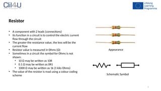
Resistor
• A componentwith 2 leads (connections)
• Its function in a circuit is to control the electric current
flow through the circuit
• The greater the resistance value, the less will be the
current flow
• Resistor value is measured in Ohms (Ω)
• Sometimes in a circuit the symbol for Ohms is not
shown:
• 10 Ω may be written as 10R
• 0.1 Ω may be written as 0R1
• 1000 Ω may be written as 1k (1 kilo Ohms)
• The value of the resistor is read using a colour coding
scheme
Appearance
Schematic Symbol
5
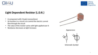
Light Dependent Resistor(L.D.R.)
• A component with 2 leads (connections)
• Its function in a circuit is to control the electric current
flow through the circuit
• The value of the resistor varies with light applied over it
• Resistance decreases as light increases
Appearance
Schematic Symbol
6.
6
Capacitor
• A componentwith 2 leads (connections)
• Its function in a circuit is to charge up to a voltage, hence
storing electrical charge (energy)
• Capacitor value is measured in Farads (F)
• Capacitors usually have a very low capacitance value:
• 0.000001 F is given as 1 µF (µ = micro = 1 x 10⁶
)
• 0.000000001 F is given as 1 nF (n = nano = 1 x 10⁹
)
• 0.000000000001 F is given as 1 pF (p = pico = 1 x 10¹²
)
• The value of the capacitor is read using a number coding
scheme
Appearance
Schematic Symbol
7.
7
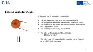
Reading Capacitor Value:
Ifthe code ‘103’ is printed on the capacitor:
• The first digit of the code is the first digit of the value
• The second digit of the code is the second digit of the value
• The third digit of the code is the number of zeros following the
first 2 digits of the value
• The resulting value is always in pico-farads
• The value of the capacitor will therefore be:
• 10000 pF or 10 nF
• The letter code 1KV means that the capacitor can be charged
up to 1000V (1kV) maximum.
8.
8
Polarized Capacitor
• Acapacitor whose leads are marked with (+) and (-)
• They are designed for higher capacitance values (range of
micro-farads)
• It is important to properly connect in the circuit to avoid
damage during operation
• Used only on DC (values of voltage that do not change
polarity)
• Capacitor marking:
• The longer lead is the (+)
• (-) lead indicated on the capacitor body
• The value and working voltage are written on the case (no
number coding used)
Appearance
Schematic Symbols
9.
9
Diode
• A componentwith 2 leads (connections)
• The connections are named ANODE and CATHODE
• Its function in a circuit is to control the direction of
electric current flow through the circuit
• When a DC voltage is applied across a diode:
• current will be allowed to pass if the (+) is
connected to the anode, and the (-) is connected to
the Cathode (DIODE IS FORWARD BIASED)
• current will not be allowed to pass if the (+) is
connected to the Cathode, and the (-) is connected
to the Anode (DIODE IS REVERSED BIASED)
• A ring printed on one side of the diode body indicates
the Cathode Lead
Appearance
Schematic Symbol
10.
10
Light Emitting Diode(L.E.D.):
• A component with 2 leads (connections)
• Its function in a circuit is to indicate the presence of
voltage, or to produce light.
• When the LED is connected in FORWARD BIAS MODE, it
will light up
• IMPORTANT :
• Never connect a LED in Reverse Bias
• it will not light up
• It will be damaged with just 5V
• The maximum voltage to be applied in Forward Bias
Mode is 5V, or the LED will be easily damaged. Appearance
Schematic Symbol
12
Transistor
• A componentwith 3 leads (connections)
• Its function in a circuit is as an electronic switch, or as an
amplifier
• Two types of transistors are available:
• NPN
• PNP
• The connections are named:
• COLLECTOR (C)
• BASE (B)
• EMITTER (E) Appearance
Schematic Symbols
14
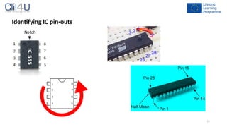
Integrated Circuits (IC)
•A component with a number of pins ranging from 8 to 40
(and more)
• A full electronic circuit is built inside the IC package, and
connected to pins located around the IC
• Each IC has its own functional circuit
• Always read the data sheet of the IC in order to find
out its function
Appearance
Schematic Symbol (example NE 555 timer IC)
16
Battery (DC PowerSupply)
• A source of DC Power used to supply electronic
components and circuits
• Can be in the form of a battery
• Can be in the form of a piece of electronic equipment
which is plugged into the 230V AC mains supply
• Called DC power supply
• Converts AC 230V into DC
• Steps down the DC into a low voltage suitable for
electronics
Appearance
Schematic Symbols
9V DC Battery Variable output DC
power supply
17.
17
Wire (Conductor)
• Usedto interconnect components to form a circuit
• Must be insulated
• Can be single stranded or multi-stranded
• Single stranded used during experiments to insert into the
prototyping (Breadboard) Board
• Multi-stranded type used in practice for improved flexibility
• In the circuit schematics, a wire is drawn as a LINE
Appearance
Schematic Symbols
Single stranded
wire
Multi-stranded
wire
18.
18
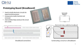
Prototyping Board (Breadboard)
•Used to build electronic circuits for
experimental purposes
• Components easily inserted and
removed
• Internal links help construct the circuit
very easily
Constructing a circuit on a Breadboard
Breadboard connections