Terminating and Connecting Electrical Wiring and Electronic Circuits (TCEC) .pptx
1) The document discusses electrical wiring and circuit diagrams. It defines key terms like load, source, and switch symbols.
2) It explains the basic steps for single pole and 3-way switch wiring installations, including connecting the source lines and load lines.
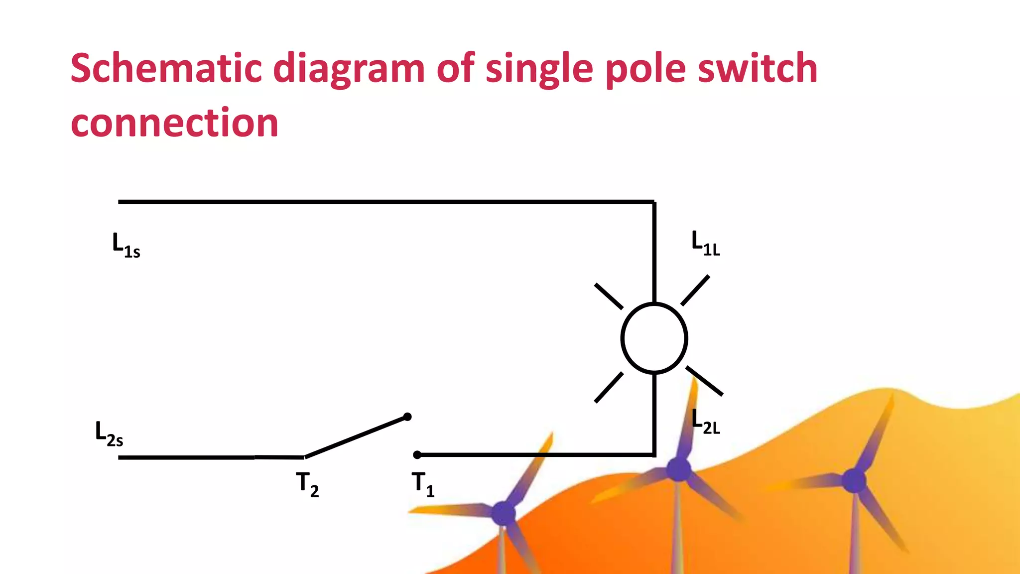
3) Examples of schematic and actual wiring diagrams are provided for single pole and 3-way switch connections to illustrate the concepts.
What are thethings to
consider in
planning / preparing
electrical wiring or
electronic circuit correctly?
5.
Electrical & Electronicsymbols and
images are used by engineers in circuit
diagrams and schematics to show how a
circuits components are connected
together.
6.
Different terms andsymbols
• Load
are electrical devices like lighting fixture and appliances
that consumes electrical energy
• Source
electrical energy coming from either alternating current or
direct current that provides electrical power to the circuit.
• L1s
= Line 1 of the source
• L2s
= Line 2 of the source
7.
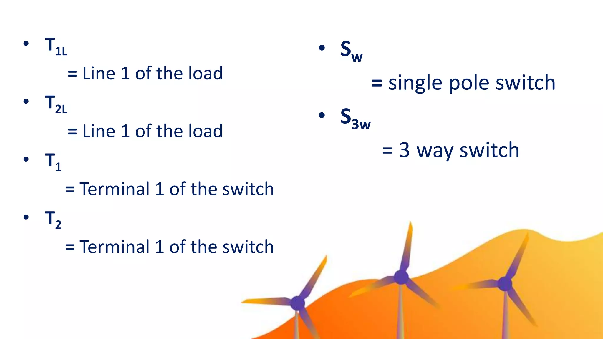
• T1L
= Line1 of the load
• T2L
= Line 1 of the load
• T1
= Terminal 1 of the switch
• T2
= Terminal 1 of the switch
• Sw
= single pole switch
• S3w
= 3 way switch
8.
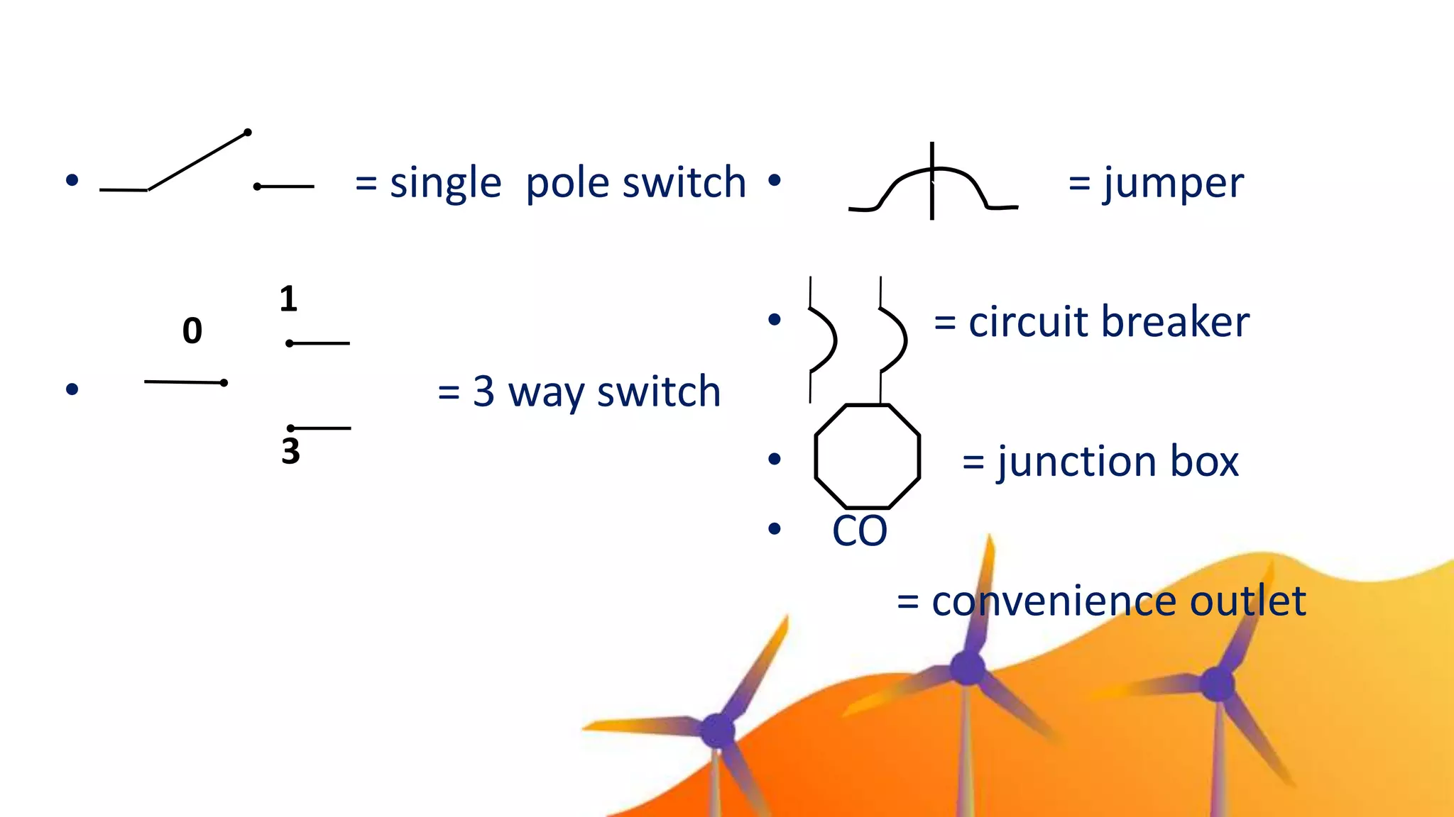
• = jumper
•= circuit breaker
• = junction box
• CO
= convenience outlet
`
• = single pole switch
• = 3 way switch
0
1
3
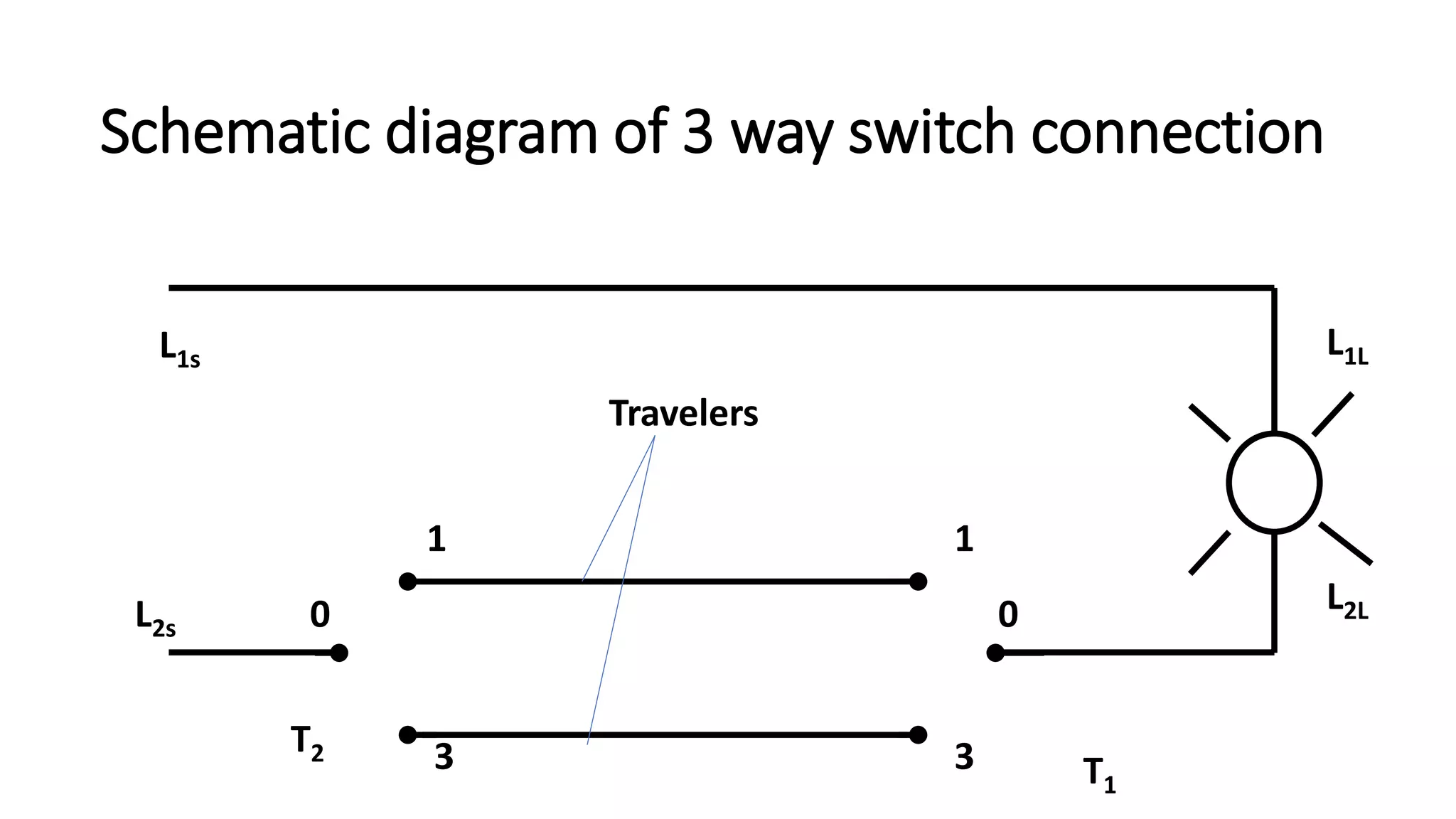
9.
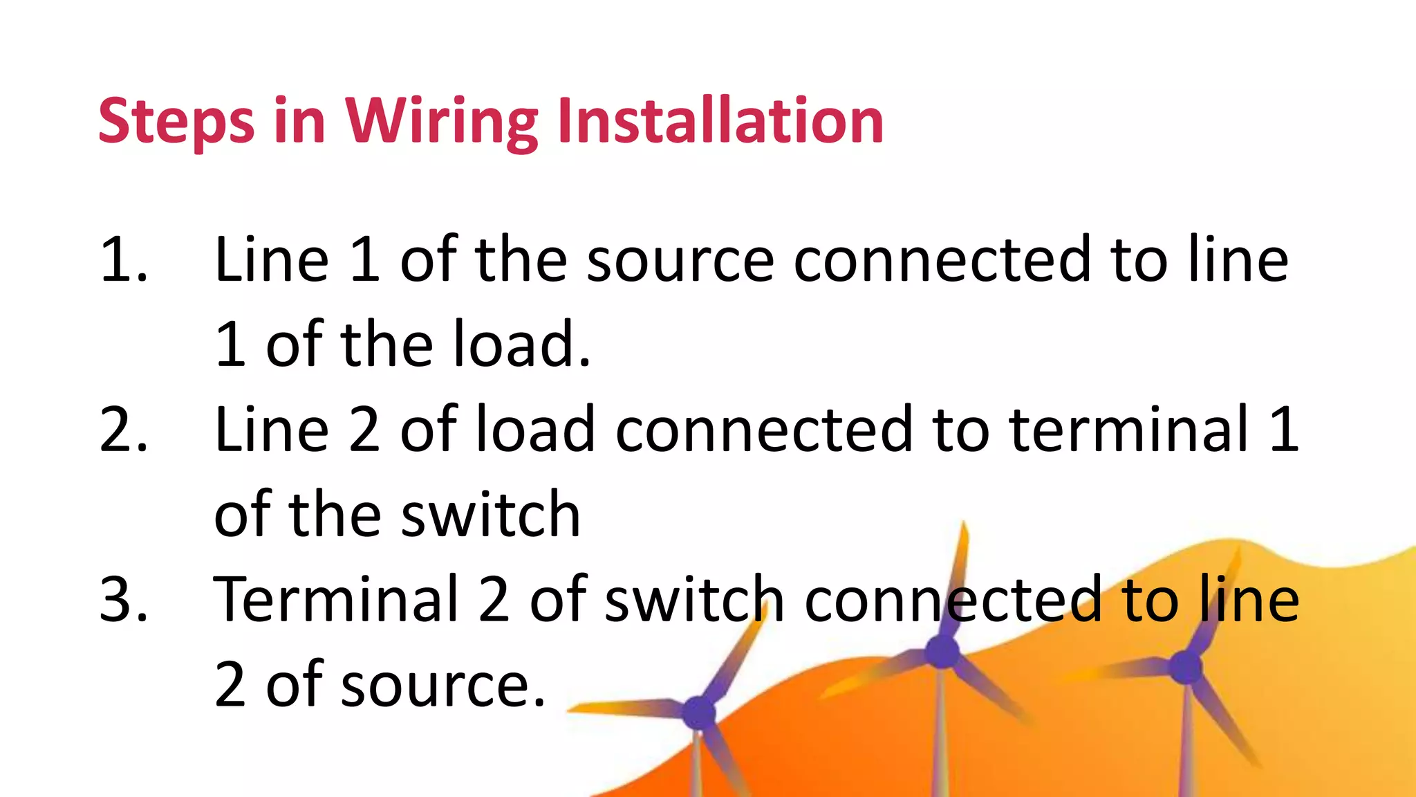
Steps in WiringInstallation
1. Line 1 of the source connected to line
1 of the load.
2. Line 2 of load connected to terminal 1
of the switch
3. Terminal 2 of switch connected to line
2 of source.
Travelers - providestwo alternate
pathways for hot current to flow between
the switches—this is what allows the
switches to turn the lights on and off in a
flexible manner
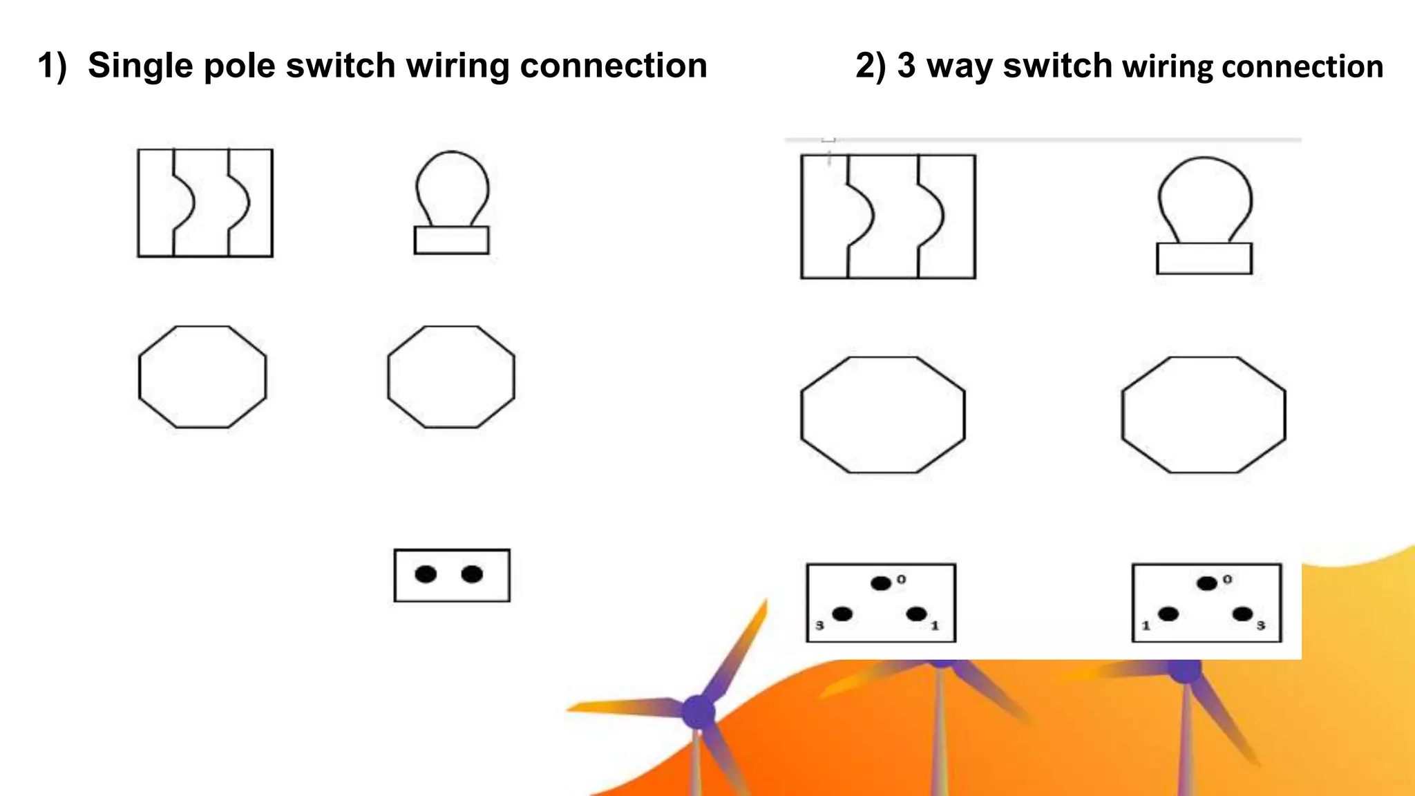
1) Single poleswitch wiring connection 2) 3 way switch wiring connection
18.
As a student,is wiring installation
can give benefit to you? In what
possible way?
19.
• What arethe terms use in wiring
installation? Draw its symbol.
• Recite the basic steps in building wiring
installation?
• In what specific lesson of other areas
we can integrate this lesson?
20.
Assuming that youare an electrical engineer,
your client ask you to draw an actual wiring
diagram of a house with materials of 2
junction box, 1 circuit breaker, and 1
lightbulb controlled by single pole switch
(Sw).
With this material, draw your own actual
wiring diagram.
Do it yourself!!
21.
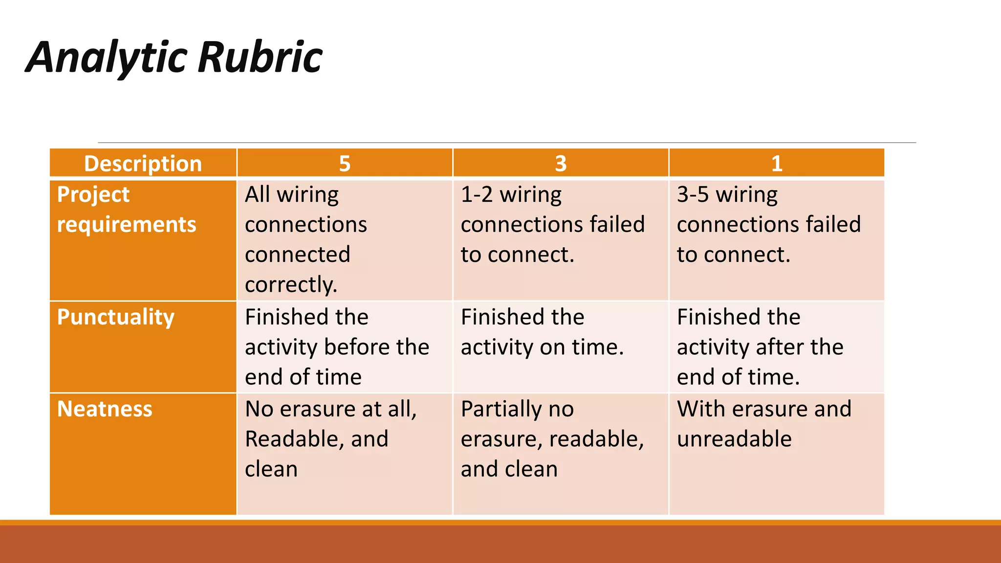
Analytic Rubric
Description 53 1
Project
requirements
All wiring
connections
connected
correctly.
1-2 wiring
connections failed
to connect.
3-5 wiring
connections failed
to connect.
Punctuality Finished the
activity before the
end of time
Finished the
activity on time.
Finished the
activity after the
end of time.
Neatness No erasure at all,
Readable, and
clean
Partially no
erasure, readable,
and clean
With erasure and
unreadable


![Performing Computer Operations [Autosaved].pptx](https://cdn.slidesharecdn.com/ss_thumbnails/performingcomputeroperationsautosaved-230213131335-0c4b802d-thumbnail.jpg?width=640&height=640&fit=bounds)


