Downloaded 16 times

![IV.1 Ultrasonic Sensors
It is the heart of the suggested device. We have used ultrasonic sensor type SRF04, known as
ultrasonic range finder. The SRF04 is a light weight ( of 0.4 Oz), small size ( 4 cm wide, 2 cm
height and 1.5 cm depth) sensor and produces ultrasound of 40 KHz frequency and has built-
in transmitter and receiver. It operates from 5 V DC and consumes 30 mA to 50 mA current.
The maximum range of this sensor is 3 meters. This sensor can detect a stick having diameter
of 3 cm from a distance of 2 meters or more.
This SRF04 uses a microcontroller and requires an input trigger pulse of minimum 10 micro
second widths. In operation the processor of SRF04 waits for a trigger pulse. After receiving a
proper trigger pulse the processor will generate eight cycles of sonic burst of 40 kHz. This sonic
burst will be reflected back to the sensor by any obstacle that is situated within the range 3
meters. Accordingly an echo pulse whose width is proportional to obstacle distance will be
generated by the microcontroller. The width of the echo pulse can be anywhere between 100
microsecond to 18 m sec, if there is any obstacle present within the specified range. The
minimum pulse width is 100 microseconds corresponds to a distance of 1.67 meter and the
maximum pulse width of 18 m sec corresponds to a distance of 3 meters. However if there is
no obstacle within the range of 3 meters then width of the echo pulse will be 36 m sec.
IV.2. Input Trigger
The ultrasonic sensor SRF04 should be triggered regularly at a specified time interval for
continuous distance measurement. Considering the walking speed of a blind person in an
unknown place as 1.5 km/hour, the time taken to travel 1 meter is 2.4 second. The sensor needs
to be triggered at the time interval of 2.4 second which corresponds to a clock frequency of
0.417Hz. The timer IC 555 in a stable configuration is used to generate trigger pulses of
0.417Hz frequency [11].
IV.3. Reset Circuit
This circuit will generate pulse automatically to reset all the counters so that a new set of data
may enter into the counter. The reset pulse should be synchronized with the input trigger pulse
that is used to trigger the ultrasonic sensor. Every time a trigger pulse appears there should be
a corresponding reset pulse. Once again 555 timer has been used as a monostable multivibrator
that is triggered by the input trigger pulse to generate the required reset pulse.
V. Design Parameters
The proposed ETA is designed according to the following parameters:
Detectable range in meter 0.2 to 2.5
Weight in gram 300 to 350
Operating Voltage 9V
Allowable input frequency 40 kHz
Sensitivity in db -63±3
Operating temp. Range (o
C) -30 to +85](https://image.slidesharecdn.com/safetyguardforblind-160529155102/85/Safety-guard-for-blind-3-320.jpg)
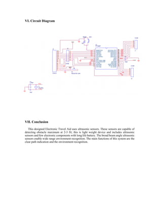


This document describes an electronic travel aid device for the blind using ultrasonic sensors to detect obstacles. It consists of an ultrasonic sensor that transmits ultrasound beams to detect objects within 2-3 meters. The distance to objects is categorized into discrete levels of 1, 2, or 3 meters which are indicated to the user via tactile vibrators. The device also detects water pits using audio signals to inform users. It aims to provide mobility information to visually impaired people to help them safely navigate environments.


