
Recommended
More Related Content
What's hot
What's hot (20)
Similar to obstacle avoiding robot
Similar to obstacle avoiding robot (20)
Recently uploaded
Recently uploaded (20)
obstacle avoiding robot
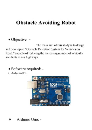
- 1. Obstacle Avoiding Robot Objective: - The main aim of this study is to design and develop an “Obstacle Detection System for Vehicles on Road.”capable of reducing the increasing number of vehicular accidents in our highways. Software required: - i. Arduino IDE Arduino Uno: -
- 2. Arduino is an open-sourceplatform used for building electronicsprojects. The Arduino UNO is an open-sourcemicrocontrollerboard based on the Microchip ATmega328P microcontrollerand developed by Arduino.cc. o It can be powered by a USB cable or by an external 9-volt battery, though it accepts voltages between 7 and 20 volts. Requirements: - Chassis OR any toy car. Arduino UNO/Mega. Ultrasonic sensor HC SR-04. 2 DC motors. 9V/12V 1A battery. Motordriver moduleL298. Jumpers. Single stranded wires. Procedure: - So yes, I’m going to divide the whole making into 4 part Connectionsof Ultrasonic-sensor → Connectionsof L298N → Code → Testing
- 4. Ultrasonic Sensor: - Connections for Obstacle avoiding robot: - Connectionsof Ultrasonic-sensor:- i) VCC – VCC terminal of Arduino. ii) GND – GND terminal of Arduino. iii) Trigpin – digital pin 9 on Arduino. iv) Echo pin – digital pin 10 on Arduino. Ultrasonic Sensor: - An Ultrasonic sensor is a device that can measure the distance to an object by using sound waves. It measures distance by sending out a sound wave at a specific frequency and listening for that sound wave to bounce back. By recording the elapsed time between the sound wave being generated and the sound wave bouncing back, it is possible to calculatethe distance between the sonar sensor and the object.
- 5. Motor Driver L298N: - Pulse width modulation (PWM), or pulse-duration modulation (PDM), is a method of reducing .... The simplest way to generate a PWM signal is the intersective method, which requires only a sawtooth or a triangle .... electronic circuitry which suppresses current flow during defined portions of each cycle of the AC line voltage
- 6. Connections of L298N: - i. +12V – Positive terminal of the battery. ii. GND – a) GND of Arduino b) Negative terminal of battery. iii. Input terminal 1 – Pin 4 iv. Input terminal 2 – Pin 5 v. Input terminal 3 – Pin 6 vi. Input terminal 4 – Pin 7 vii. Output terminal 1 – Positive of first motor. viii. Output terminal 2 – Negative of first motor. ix. Output terminal 3 – Positive of second motor. x. Output terminal 4 – Negative of second motor. Coding: - int trigPin = 9; int echoPin = 10; int revright = 4; //REVerse motion of Right motor int fwdleft = 7; int revleft= 6; int fwdright= 5; //ForWarD motion of Right motor int c = 0; void setup() { //Serial.begin(9600); pinMode(5, OUTPUT); pinMode(6, OUTPUT); pinMode(4, OUTPUT); pinMode(7, OUTPUT); pinMode(trigPin, OUTPUT);
- 7. pinMode(echoPin, INPUT); // put your setup codehere, to run once: } void loop() { long duration, distance; digitalWrite(trigPin,HIGH); delayMicroseconds(1000); digitalWrite(trigPin, LOW); duration=pulseIn(echoPin, HIGH); distance =(duration/2)/29.1; //Serial.print(distance); //Serial.println("CM"); delay(10); if((distance>20)) { digitalWrite(5,HIGH); // If you dont get propermovements of your robot, digitalWrite(4,LOW); // then alter the pin numbers digitalWrite(6,LOW); // digitalWrite(7,HIGH); // } else if(distance<20) { digitalWrite(5,HIGH); digitalWrite(4,LOW); digitalWrite(6,HIGH); //HIGH
- 8. digitalWrite(7,LOW); } } .Project final shape: - Submitted By: Muhammad Faseeh