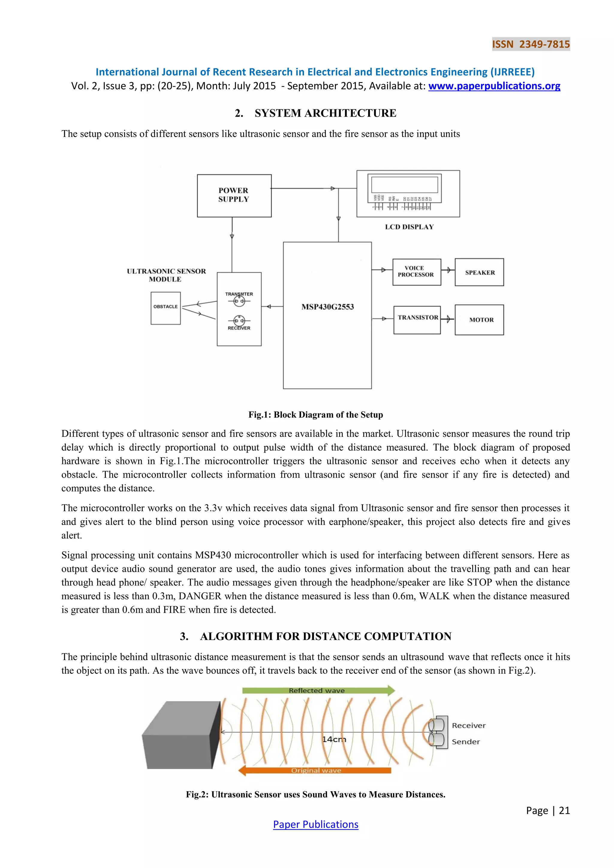
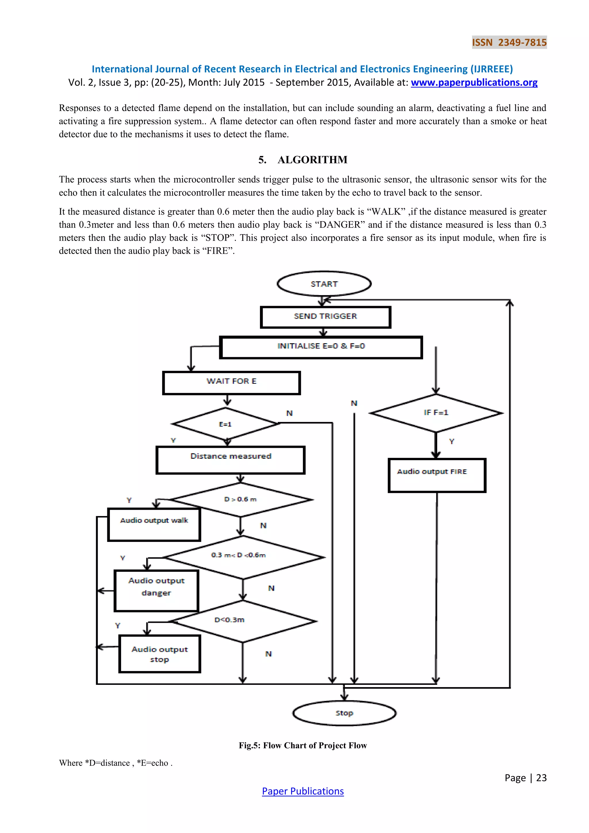
This document describes an annunciator system for blind persons using ultrasonic sensors. The system uses an MSP430 microcontroller interfaced with ultrasonic and fire sensors to detect obstacles and fires. It calculates distances based on ultrasonic pulse times and provides audio alerts through headphones. If an obstacle is detected within 0.3m it says "STOP", within 0.6m it says "DANGER", and beyond 0.6m it says "WALK". If a fire is detected it says "FIRE". The system is intended to help blind persons navigate safely and avoid hazards. Experimental results showed the system can successfully detect obstacles and alert the user.
![ISSN 2349-7815
International Journal of Recent Research in Electrical and Electronics Engineering (IJRREEE)
Vol. 2, Issue 3, pp: (20-25), Month: July 2015 - September 2015, Available at: www.paperpublications.org
Page | 20
Paper Publications
Annunciator for Blind Person Using Ultrasonic
Sensor
Mrs. Lalita K1
, Arpita Ghosh2
, Ashwini G3
, Archana S4
1
Assistant Professor, GSSSIETW
2,3,4
U.G Student, GSSSIETW
Abstract: The challenges faced by the blind people in their everyday lives are not well understood, obstacle
avoidance problem is an essential part of navigation for the blind. The challenging task is to work with a path
where the environment is completely unknown .This paper contains a method to implement a mobility aid for blind
person, it provides the information to avoid obstacles distance based on ultrasonic sensors and this also can be used
in automatic robots, self-propelling vehicles in automated production factories etc. Model contains signal
processing unit with MSP430 microcontroller which receives data from Ultrasonic sensor then process it and gives
alert to the blind person using voice processor with earphone/speaker.
Keywords: MSP430, Signal Processing unit, Ultrasonic sensor, fire sensor, Voice processor.
1. INTRODUCTION
Mobility for the blind can be defined as the ability to move with ease, speed and safety through his environment
independently. With the advances of modern technologies many different types of devices are available to support the
mobility of blind which are generally known as electronic travel aid which aims at conveying information about the
environment to visually impaired individuals, so that they can exploit part of the information that sighted people normally
use to experience the world and navigate it.
There are various methods to measure the distance of obstacle. One of the methods is by means of ultrasonic. Audible
electronic mobility aid and obstacle detector designed for use by individuals who are blind or have low vision, it is a small
electronic device aids users who are blind or visually impaired with orientation and mobility. By listening to sounds
produced by the device, users can determine the distance and location of objects and some of the object's features.
Ultrasonic sensors emit short, high-frequency sound pulses at regular intervals. These propagate in the air at the velocity of
sound. If they strike an object, then they are reflected back as echo signals to the sensor, which itself computes the distance
to the target based on the time-span between emitting the signal and receiving the echo. The main reason to use ultrasonic
sensor is that, the ultrasonic method has unique advantages over conventional sensors are, discrete distances to moving
objects can be detected and measured. Less affected by target materials and surfaces, and not affected by colour. Solid-
state units have virtually unlimited, maintenance free life.
The device attaches to the golf grip handle of a long cane or onto gloves which is worn by the blind person. A headphone
provides audio feedback. The device comes with headphones and an instructional audiotape with sample sounds and a
vibrator which vibrates when obstacle is detected. The device also incorporates a fire sensor to alert the blind person if fire
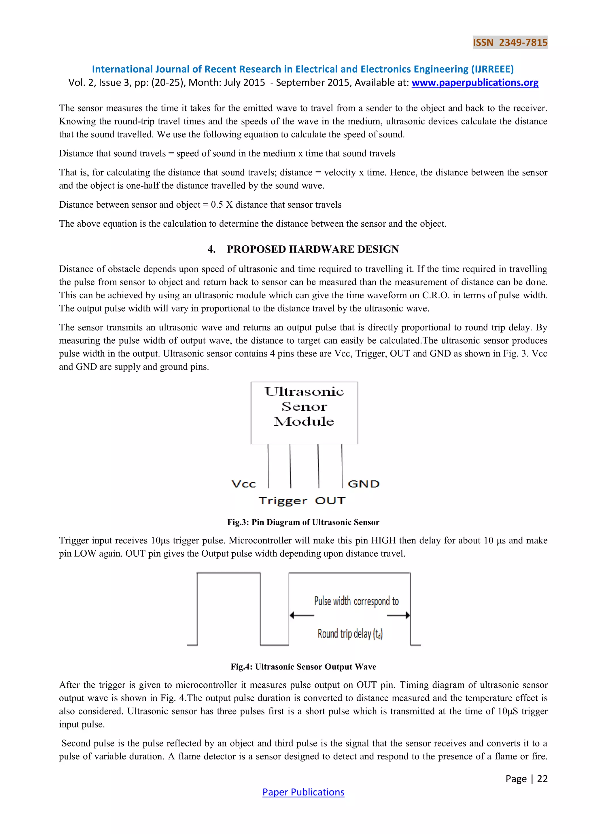
is detected. Ultrasonic sensors are based on the output waveform whose pulse width varies with round trip delay time of
ultrasonic pulse or distance measured. A fire sensor detects the presence of flame within the coverage area. In An
Electronic Travel Aid for Navigation of Visually Impaired Persons [2] a survey was done of various ETAs based on
features and performance parameters. In Obstacle Avoidance Electronic Travel Aids for Blind [3] the author develops a
navigational/orientation system that uses RFID technology, GPS and computer vision. In Electronic white cane for blind
people navigation assistance”, World Automation Congress (WAC). In [7] a bus detection mechanism for the blind in
travelling from one place to other using RFID system was developed](https://image.slidesharecdn.com/annunciatorforblindpersonusingultrasonicsensor-392-170328064806/75/Annunciator-for-Blind-Person-Using-Ultrasonic-Sensor-1-2048.jpg)
![ISSN 2349-7815
International Journal of Recent Research in Electrical and Electronics Engineering (IJRREEE)
Vol. 2, Issue 3, pp: (20-25), Month: July 2015 - September 2015, Available at: www.paperpublications.org
Page | 24
Paper Publications
6. EXPERIMENTAL RESULTS
The intelligent cane has been evaluated with the ultrasonic sensor the ultrasonic sensors based on the pulse width. The HC-
SR04 ultrasonic sensor is used to design this project; it uses sonar to determine distance.
Fig.6: Annunciator for Blind Person using Ultrasonic Sensor module
It offers excellent non-contact range detection with high accuracy and stable readings in an easy-to-use package. From
2cm to 400cm or 1” to 13feet. Its operation is not affected by sunlight or black material like Sharp rangefinders. It comes
complete with ultrasonic transmitter and receiver module. Distance information is then conveyed to the user though a
buzzer and vibrator.
7. CONCLUSION
In this paper, we have presented new intelligent system for guiding individuals who are blind or partially sighted, and we
have described how the system can be used to enable those people to move with the same ease and confidence as a sighted
people.
The system has been used to receive the data from the sensing devices and command. We have integrated the ultrasonic
sensor data in order to detect obstacles, and to obtain more detailed regarding the blind’s environment. Evaluations of the
system that we have developed have been conducted by attaching the prototype to the handle of the white cane. The
experimental results have shown the usefulness of the system in allowing blind people to move independently, safely and
quickly among obstacles and hazardous places
ACKNOWLEDGMENT
We take this opportunity to thank Dr. K. A. Sumithra Devi, Principal, GSSSIETW, Mysuru, our H.O.D, Mr M.V.
Sreenivas Rao, Dept.of Instrumentation Technology, Mrs. Lalitha .K , Assistant Professor, Internal guide for their support.
REFERENCES
[1] Kumar,A. Checktronix India Pvt. Ltd., Chennai, India Patra, R. ; Manjunatha, M. ;Mukhopadhyay, J. ; Majumdar,
A.K.( An electronic travel aid for navigation of visually impaired persons) Print ISBN:978-1-4244-8952-7,INSPEC
Accession Number:11835160
[2] Amit Kumar, Rusha Patra, M. Manjunatha, J. Mukhopadhyay and A. K. Majumdar, IIT, Kharagpur “An Electronic
Travel Aid for Navigation ofVisually Impaired Persons” International Conference on Communication Systems and
Networks (COMSNETS), PP-1-5, IEEE 2011.
[3] Dimitrios Dakopoulos and Nikolaos G. Bourbakis, “Wearable ObstacleAvoidance Electronic Travel Aids for Blind:
A Survey”, Transactions onSystems, Man, and Cybernetics, Vol. 40, Issue no. 1, IEEE 2010.
[4] Faria J, Lopes S, Fernandes H, Martins P, Barroso J, “Electronic white cane for blind people navigation assistance”
,World Automation Congress (WAC), PP-1-7, sept 2010](https://image.slidesharecdn.com/annunciatorforblindpersonusingultrasonicsensor-392-170328064806/75/Annunciator-for-Blind-Person-Using-Ultrasonic-Sensor-5-2048.jpg)
![ISSN 2349-7815
International Journal of Recent Research in Electrical and Electronics Engineering (IJRREEE)
Vol. 2, Issue 3, pp: (20-25), Month: July 2015 - September 2015, Available at: www.paperpublications.org
Page | 25
Paper Publications
[5] Bruno Ando, and Salvatore Graziani, “Multisensor Strategies to Assist Blind People : A Clear-Path Indicator”,
Transactions on Instrumentation and Measurement, Vol. 58, Issue no. 8, PP- 2488-2494, IEEE 2009.
[6] . A. A. Tahat “A Wireless Ranging System for the Blind Long- Cane Utilizing a Smart-Phone” 10th International
Conference on Telecommunications (Con TEL), PP-111-117, IEEE 2009.
[7] Mohammad FaridSaaid, Ismarani Ismail, Mohd Zikrul Hakim Noor, “Radio Frequency Identification Walking Stick
(RFIWS): A Device for the Blind”, 5th International Colloquium on Signal Processing & Its Applications (CSPA),
PP-250-253, IEEE 2009.
[8] MohdZikrul Hakim Noor, Ismarani Ismail and Mohammad FaridSaaid, “Bus Detection Device for the Blind Using
RFID Application” 5th International Colloquim on Signal Processing and Its Applications, PP-247-249, IEEE 2009.
[9] S. Innet , N. Ritnoom “An Application of Infrared Sensors for Electronic White Stick” International Symposium on
Intelligent Signal Processing and Communication Systems (ISPACS), PP-1-4, IEEE 2009.
[10] C. Gearhart, A. Herold, B. Self, C. Birdsong, L. Slivovsky, "Use of ultrasonic sensors in the development of an
Electronic Travel Aid," Sensors Applications Symposium, (SAS), PP-275-280, IEEE 2009.
[11] B. Ando, “A Smart Multi sensor Approach to Assist Blind People in Specific Urban navigation tasks”, Transaction
on Neural Systems and Rehabilitation Engineering, Vol. 16, Issue no. 6, PP- 592-594, IEEE 2008.
[12] G. Balakrishnan, G. Sainarayanan, R. Nagarajan and S. Yaacob, “Wearable Real-Time Stereo Vision for the Visually
Impaired,” Engineering Letters, Vol. 14, no. 2, IEEE 2006.](https://image.slidesharecdn.com/annunciatorforblindpersonusingultrasonicsensor-392-170328064806/75/Annunciator-for-Blind-Person-Using-Ultrasonic-Sensor-6-2048.jpg)