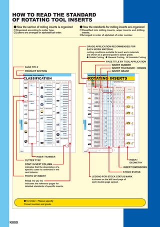
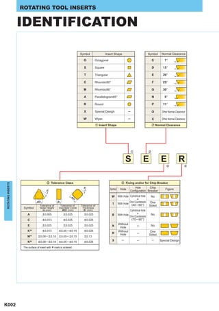
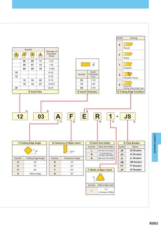
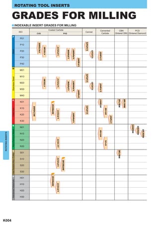
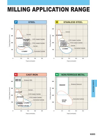
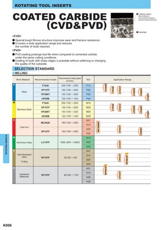
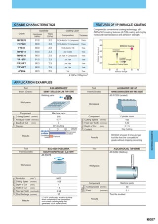
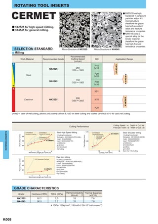
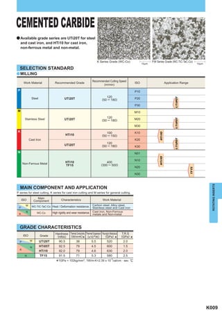
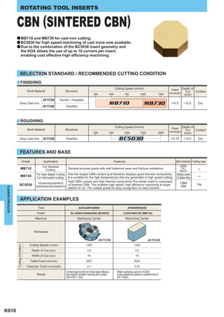
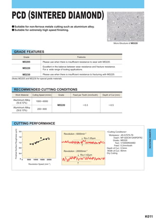
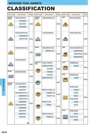
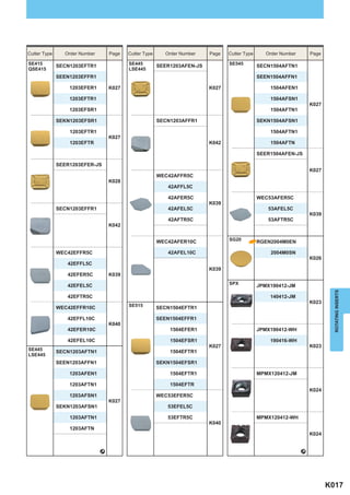
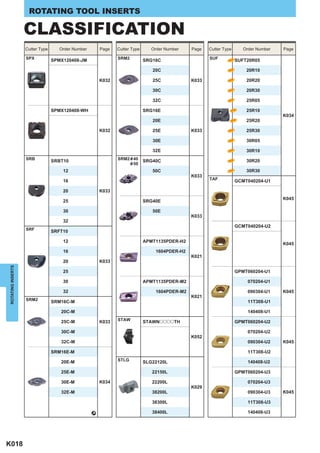
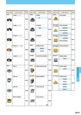
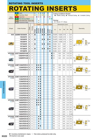
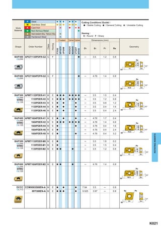
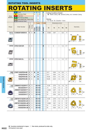
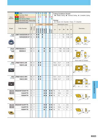
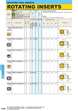
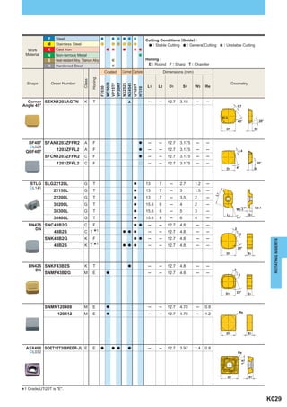
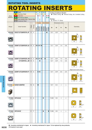
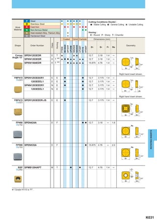
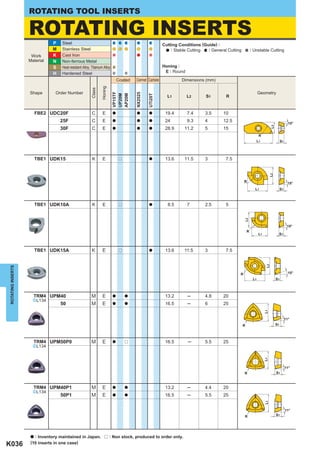
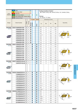
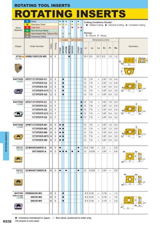
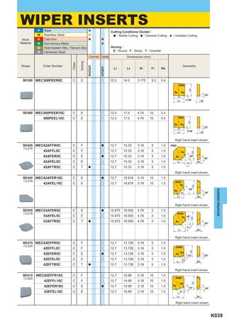
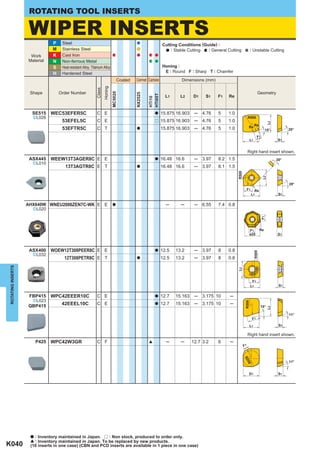
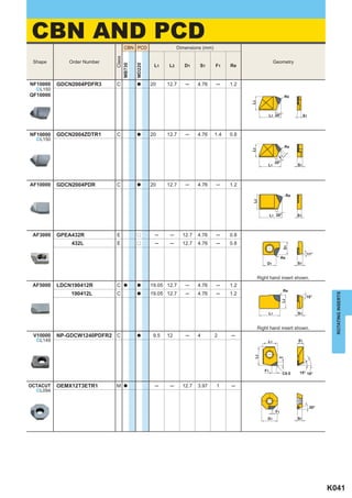
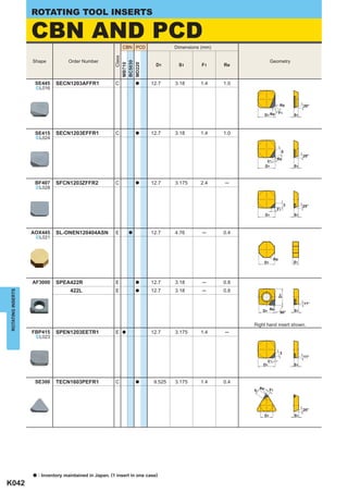
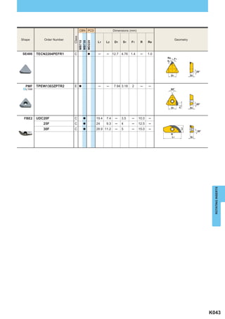
1. HOW TO READ THE STANDARD
OF ROTATING TOOL INSERTS
a How the section of milling inserts is organized a How the standards for milling inserts are organized
zOrganized according to cutter type. zClassified into milling inserts, wiper inserts and drilling
xCutters are arranged in alphabetical order. inserts.
xArranged in order of alphabet of order number.
GRADE APPLICATION RECOMMENDED FOR
EACH WORK MATERIAL
cutting conditions suitable for each work materials
are shown as a general guide to select grade.
:Stable Cutting :General Cutting :Unstable Cutting
PAGE TITLE BY TOOL APPLICATION
INSERT NUMBER
PAGE TITLE INSERT TOLERANCE • HONING
PRODUCT SECTION INSERT GRADE
ROTATING TOOL INSERTS ROTATING TOOL INSERTS
CLASSIFICATION ROTATING INSERTS
P Steel Cutting Conditions (Guide) :
Cutter Type Order Number Page Cutter Type Order Number Page Cutter Type Order Number Page M Stainless Steel : Stable Cutting : General Cutting : Unstable Cutting
Work K Cast Iron
AF3000 AJX APX4000
GPEA432R JOMW06T215ZZSR-FT AOMT184804PEER-H Material N Non-ferrous Metal
S Heat-resistant Alloy, Titanium Alloy Honing :
432L 080320ZZSR-FT 184808PEER-H E : Round F : Sharp
H Hardened Steel
K041 JDMW09T320ZDSR-FT K022 184816PEER-H Coated Cermet Carbide Dimensions (mm)
Honing
Class
120420ZDSR-FT 184832PEER-H K020
Shape Order Number Geometry
MC5020
VP20RT
VP15TF
NX2525
UP20M
UTi20T
L1 L2 S1 F1 Re
F7030
HTi10
TF15
140520ZDSR-FT 184840PEER-H
SPEA422R JOMT06T215ZZSR-JM 184850PEER-H
BAE AEMW150304ER M E a a a a a 15.875 9.525 3.18 ─ 0.4
422L 080320ZZSR-JM 184864PEER-H 150304FR M F a 15.875 9.525 3.18 ─ 0.4
150308ER M E a a a a a 15.875 9.525 3.18 ─ 0.8 Re
K042 JDMT09T320ZDSR-JM K022 AOMT184804PEER-M
150308FR M F a 15.875 9.525 3.18 ─ 0.8
L2
120420ZDSR-JM 184808PEER-M 20°
19T304ER M E a a a a a 19.05 12.7 3.97 ─ 0.4 L1 S1
85°
140520ZDSR-JM 184810PEER-M 19T304FR M F a 19.05 12.7 3.97 ─ 0.4
K020
AF5000 19T308ER M E a a a a a 19.05 12.7 3.97 ─ 0.8
LDCN190412R JDMT120420ZDSR-ST 184812PEER-M
19T308FR M F a 19.05 12.7 3.97 ─ 0.8
190412L 140520ZDSR-ST 184816PEER-M
APX3000 AOGT123602PEFR-GM G F a 12 6.6 3.6 1.8 0.2
K023
^L050 L1
K041 184820PEER-M 123604PEFR-GM G F a 12 6.6 3.6 1.6 0.4
F1
AQX 123608PEFR-GM G F a 12 6.6 3.6 0.4 0.8
L2
QOMT0830R-M2
11°
AOX445 Re S1
SL-ONEN120404ASN 1035R-M2
AF10000 GDCN2004PDR 1342R-M2 APX3000 AOMT123604PEER-H M E a a a 12 6.6 3.6 1.6 0.4
K042 ^L050 L1
123608PEER-H M E a a a 12 6.6 3.6 1.2 0.8
1651R-M2 K025
F1
L2
123616PEER-H M E a a a 12 6.6 3.6 1.2 1.6
K041 1856R-M2 11°
Re S1
APX3000 2062R-M2
AOGT123602PEFR-GM
123604PEFR-GM 2576R-M2 APX3000 AOMT123602PEER-M M E a a 12 6.6 3.6 1.8 0.2
^L050
K020 123604PEER-M M E a a 12 6.6 3.6 1.6 0.4
AHX640W NNMU200608ZEN-MK 123608PEFR-GM QOGT0830R-G1
123608PEER-M M E a a 12 6.6 3.6 1.2 0.8
ROTATING INSERTS
ROTATING INSERTS
1035R-G1 123610PEER-M M E a a 12 6.6 3.6 1.0 1.0 L1
K024 AOMT123602PEER-M 1342R-G1 123612PEER-M M E a a 12 6.6 3.6 0.8 1.2
F1
L2
123616PEER-M M E a a 12 6.6 3.6 0.4 1.6 11°
123604PEER-M 1651R-G1 K025 Re S1
123620PEER-M M E a a 12 6.6 3.6 0.4 2.0
123608PEER-M 1856R-G2 123624PEER-M M E a a 12 6.6 3.6 0.4 2.4
NNMU200608ZEN-HK 123610PEER-M 2062R-G1 123630PEER-M M E a a 12 6.6 3.6 0.4 3.0
123632PEER-M M E a a 12 6.6 3.6 0.4 3.2
123612PEER-M 2576R-G1
K020 APX4000 AOMT184804PEER-H M E a a a 18 9 4.8 1.8 0.4
K024 123616PEER-M ARX ^L056
RDMW0517M0E 184808PEER-H M E a a a 18 9 4.8 1.4 0.8
L1
123620PEER-M 0620M0E 184816PEER-H M E a a a 18 9 4.8 0.4 1.6 15°
K025
F1
a
L2
184832PEER-H M E 18 9 4.8 0.4 3.2
123624PEER-M 0724M0E
184840PEER-H M E a 18 9 4.8 0.4 4.0 Re S1
WNEU2006ZEN7C-WK 123630PEER-M a
184850PEER-H M E 18 9 4.8 ─ 5.0
123632PEER-M ASX400 a
SOET12T308PEER-JL 184864PEER-H M E 18 9 4.8 ─ 6.35
APX4000 AOMT184804PEER-M M E a a 18 9 4.8 1.8 0.4
AOMT123604PEER-H ^L056
K040 184808PEER-M M E a a 18 9 4.8 1.4 0.8 L1
123608PEER-H K029
184810PEER-M M E a 18 9 4.8 1.0 1.0 15°
K020
F1
L2
123616PEER-H 184812PEER-M M E a 18 9 4.8 0.8 1.2
Re S1
184816PEER-M M E a a 18 9 4.8 0.4 1.6
_
184820PEER-M M E a 18 9 4.8 0.4 2.0
a : Inventory maintained in Japan. r : Non stock, produced to order only.
(10 inserts in one case)
K012 K020
INSERT NUMBER
CUTTER TYPE INSERT
GEOMETRY
CONT. IN NEXT COLUMN
indicates that the description of a INSERT DIMENSIONS
specific cutter is continued in the
next column. STOCK STATUS
PHOTO OF INSERT LEGEND FOR STOCK STATUS MARK
is shown on the left hand page of
PAGE TO GO TO each double-page spread.
indicates the reference pages for
detailed standards of specific inserts.
a To Order : Please specify
zinsert number and grade.
K000
3. ROTATING TOOL INSERTS
IDENTIFICATION
Symbol Insert Shape Symbol Normal Clearance
O Octagonal C 7°
S Square D 15°
T Triangular E 20°
C Rhombic80° F 25°
M Rhombic86° G 30°
A Parallelogram85° N 0°
R Round P 11°
X Special Desigh ─ O Other Normal Clearance
W Wiper ─ X Other Normal Clearance
z Insert Shape x Normal Clearance
z x
S E E R
c v
c Tolerance Class v Fixing and/or for Chip Breaker
ROTATING INSERTS
Hole Chip
m
Symbol Hole Figure
Configuration Breaker
m
øD W With Hole Cylindrical Hole No
1 +
øD1 S1 One Countersink One
T With Hole (40 ─ 60°)
Tolerance of Tolerance of Tolerance of Sided
Symbol Nose Height Inscribed Circle Thickness
m (mm) & D1 (mm) S1 (mm) Cylindrical Hole
A e0.005 e0.025 e0.025 B With Hole + No
One Countersink
C e0.013 e0.025 e0.025 (70 ─ 90°)
E e0.025 e0.025 e0.025 Without No
N ─
Hole
K* e0.013 e0.05 ─ e0.15 e0.025
R
Without
Hole ─
One
Sided
M* e0.08 ─ e0.18 e0.05 ─ e0.15 e0.13
X ─ ─ ─ Special Design
N* e0.08 ─ e0.18 e0.05 ─ e0.15 e0.025
The surface of insert with
* mark is sintered.
K002
4. Symbol Honing
E
Round
Symbol
Diameter of
Inscribed
Circle
F
Sharp
06 06 11 6.35
S1
08 07 13 7.94 T
09 09 16 9.525 Chamfer
10 10.00 Insert
R
Symbol Thickness S R
12 12.00 (mm)
Chamfer+Hone
12 12 22 12.70 03 3.18
16 15 27 15.875 T3 3.97 Z Chamfer
20 20.00 04 4.76 (Strong Cutting Edge Type)
b Insert Size n Insert Thickness . Cutting Edge Condition
b n .
12 03 A F E R 1 - JS
m , / 11 12
ROTATING INSERTS
m Cutting Edge Angle , Clearance of Wiper Insert / Hand Tool Holder u Chip Breaker
12
Symbol Hand Tool Holder Symbol Name
kr %´n L Left Hand Tool Holder JS JS Breaker
For Both Right and JH Breaker
N Left Hand Tool Holder JH
Symbol Cutting Edge Angle Symbol Clearance Angle R Right Hand Tool Holder JL JL Breaker
A 45° D 15° JM JM Breaker
E 75° E 20° FT FT Breaker
P 90° F 25° u Width of Wiper Insert
11 JP JP Breaker
Z Other Angle G 30°
a
Symbol Width of Wiper Insert
1.4
1
(1.94 only for TEKN)
K003
5. ROTATING INSERTS
K004
▪
P
S
K
H
N
M
Hardened Materials Heat Resistant Alloy Ti Alloy Non-Ferrous Metal Cast Iron Stainless Steel Steel
ISO
S30
S20
S10
S01
K30
K20
K10
K01
P40
P30
P20
P10
P01
H30
H20
H10
H01
N30
N20
N10
N01
M40
M30
M20
M10
M01
MC5020
FH7020
CVD
F7030 F7030
MP8010 MP8010
NEW
NEW
VP15TF VP15TF LC15TF VP15TF VP15TF VP15TF
Coated Carbide
MP9030
NEW
PVD
UP20M UP20M
ROTATING TOOL INSERTS
VP20RT VP20RT VP20RT
a INDEXABLE INSERT GRADES FOR MILLING
VP30RT VP30RT
NX2525 NX2525 NX2525
Cermet
NX4545 NX4545
HTi10 HTi05T UTi20T UTi20T
TF15 HTi10
Carbide
Cemented
UTi20T
MB730 MB710
CBN
MB730
MD205
GRADES FOR MILLING
MD220
PCD
MD230
(Sintered CBN) (Sintered Diamond)
7. ROTATING TOOL INSERTS
COATED CARBIDE
a Coating Layers
(Wear Resistance)
(Thermal Shock Resistance)
(CVD&PVD)
(Improved Welding Resistance)
a Substrate
<CVD>
a Special tough fibrous structure improves wear and fracture resistance.
a It covers a wide application range and reduces
the number of tools required.
<PVD>
a PVD coating prolongs tool life when compared to cemented carbide
under the same cutting conditions.
a Coating of tools with sharp edges is possible without softening or changing
the quality of the subsrate.
SELECTION STANDARD
a MILLING
Recommended Cutting Speed
Work Material Recommended Grade ISO Application Range
(m/min)
P
FH7020
F7030 200 (150 ─ 250) P10
VP15TF
F7030
UP20M
VP20RT
VP15TF 150 (100 ─ 200) P20
Steel
150 (100 ─ 200)
VP30RT
VP30RT P30
UP20M 120 (100 ─ 150) P40
M F7030 200 (150 ─ 250) M10
VP15TF
F7030
UP20M
VP20RT
VP15TF 150 (100 ─ 200) M20
Stainless Steel
150 (100 ─ 200)
VP30RT
VP30RT M30
UP20M 120 (100 ─ 150) M40
K K01
MC5020 180 (100 ─ 250)
MC5020
K10
VP15TF
Cast Iron
VP20RT
K20
VP15TF 150 (100 ─ 200)
K30
ROTATING INSERTS
N N10
1000 (200 ─ 3000)
LC15TF
Aluminium Alloy LC15TF N20
N30
S S01
NEW
Heat Resistant
VP15TF
S10
MP9030
Alloy VP15TF 30 (20 ─ 40)
S20
Ti Alloy
S30 NEW
MP8010
H H01
VP15TF
H10
Hardened VP15TF 80 (50 ─ 110)
Materials H20
H30
K006
8. GRADE CHARACTERISTICS FEATURES OF VP (MIRACLE) COATING
Compared to conventional coating technology, VP
Substrate Coating Layer
(MIRACLE) coating features (Al,Ti)N coating with highly
Grade Hardness T.R.S
Composition Thickness increased heat resistance and adhesion strength.
(HRA) (GPa)
MC5020 91.0 2.2 TiCN-AI2O3-Ti Compound Thick (r)
FH7020 88.8 2.8 TiCN-AI2O3-Ti Compound Thick 900
MIRACLE Coating
F7030 88.8 2.8 TiCN-Al2O3-TiN Thin
Oxidation Temperature
Increased
800
MP8010 93.5 2.3 (Al,Ti,Si)N Thin Heat Resistance
MP9030 90.5 2.5 (Al,Ti)N-Ti Compound Thin
700
Increased
VP15TF 91.5 2.5 (Al,Ti)N Thin Adhesion Strength
VP20RT 90.5 2.5 (Al,Ti)N Thin 600
Competitor's Coating Grade
VP30RT 88.8 2.8 (Al,Ti)N Thin
50 60 70 80 (N)
UP20M 90.5 2.0 TiN Thin Adhesion Strength
*1GPa=102kg/mm
2
APPLICATION EXAMPLES
Tool ASX445R16007F Tool AHX640WR16016F
Insert (Grade) SEMT13T3AGSN-JM (VP15TF) Insert (Grade) NNMU200608ZEN-MK (MC5020)
Welding parts JIS FC250 (scaled)
Workpiece
Workpiece
Component Machine parts
Cutting Speed (m/min) 200 Component Cylinder blook
Cutting Conditions
Feed per Tooth (mm/rev) 0.27 Cutting Speed (m/min) 155
Cutting Conditions
Depth of Cut (mm) 3 Feed per Tooth (mm/rev) 0.32
Coolant Dry Cutting Depth of Cut (mm) 3─5
0 75 150 Cutting time Dry Cutting
(min/corner) Coolant
ASX445 Normal wear
ROTATING INSERTS
+
VP15TF condition
Results Competitors MC5020 showed 3 times longer
coated Fracture
Results tool life than the competitor’s
grade without chipping occurring.
Tool BXD4000-063A05RA Tool AQX204SA20L (VP30RT)
Insert (Grade) XDGT1550PDFR-G04 (LC15TF) JIS S45C (Slotting)
JIS A5078
Workpiece Workpiece
Revolution (min-1) 5600
Cutting Conditions
Cutting Speed (m/min) 1108
Component Machine parts
Depth of Cut (mm) 4
Conditions
Cutting Speed (m/min) 80
Width of Cut (mm) 1.5
Cutting
Feed per Tooth (mm/tooth) 0.34 Feed (mm/rev) 0.1
Chip Discharge (cc/min) 57 Tool life doubled.
LC15TF produced a superior surface
finish compared to the competitors Results
Results non-coated carbide grade that
generated a dull surface finish.
K007
9. ROTATING TOOL INSERTS
CERMET a NX2525 has high
hardened Ti compound
particles within it's
microstructure
therefore the grade
a NX2525 for high speed milliing. has both excellent
wear and fracture
a NX4545 for general milling. resistance properties.
a NX4545 uses a
special alloy for the
binder material
therefore the grade
has high fracture
resistance properties.
SELECTION STANDARD Micro-Structure of NX2525 Micro-Structure of NX4545
a Milling
Recommended
Work Material Recommended Grade Cutting Speed ISO Application Range
(m/min)
P
P10
NX2525
250 M10
NX2525 (150 ─ 350)
P20
Steel
NX4545
M20
150
NX4545 (120 ─ 180) P30
M30
M
K
K01
200
NX2525
Cast Iron NX2525 (150 ─ 300) K10
K20
(Note) In case of wet cutting, please use coated carbide F7030 for steel cutting and coated carbide F5010 for cast iron cutting.
Cutting Speed : vc Depth of Cut : ap
Cutting Performance
Feed per Tooth : fz Width of Cut : ae
ROTATING INSERTS
0.10
Competitor's Competitor's Steel High Speed Milling Competitor's Steel Shoulder Milling
Cermet A Fracture Cermet B Fracture Cermet A Fracture NX4545
Flank Wear (mm)
<Cutting Conditions> <Cutting Conditions>
Flank Wear (mm)
0.3 Competitor's
Competitor's Workpiece : JIS SCM440 (97W×400L) Cermet B Workpiece : JIS SCM440 (220HB)
Cermet C Fracture Cutter : SE445R0506E Fracture Cutter : NSE400R503S32
0.2 NX2525 Insert : SEEN1203AFTN1 0.05 Insert : TEEN2204PETR1
vc=350m/min vc=200m/min
0.1 ap=2.5mm fz=0.35mm/tooth
fz=0.2mm/tooth ae=25mm
Dry Cutting ap=3.0mm
1 2 3 4 10 20 30 Down Cut Dry Cutting
Machined Length per Tooth (m) Cutting Time (min)
Cast Iron Milling
K10 Cemented Carbide
Flank Wear (mm)
<Cutting Conditions>
0.3
Workpiece : JIS FC300 (95W×400L)
Cutter : SE445R0506E
0.2 Insert : SEEN1203AFTN1
vc=180m/min
NX2525 ap=2.5mm
0.1
fz=0.2mm/tooth
Dry Cutting
1 2 3
Machined Length per Tooth (m)
GRADE CHARACTERISTICS
Thermal Conductivity Thermal Expansio
Grade Hardness (HRA) T.R.S. (GPa)
NX2525 92.2 2.0
(W/m•K)
33
* (x10-6/K)
7.8
NX4545 90.0 2.2 33 7.8
* 1GPa=102kg/mm , 1W/m•K=2.39×10
2 -3
cal/cm•sec•r
K008
10. CEMENTED CARBIDE
a Available grade series are UTi20T for steel
and cast iron, and HTi10 for cast iron,
non-ferrous metal and non-metal.
K Series Grade (WC-Co) P,M Series Grade (WC-TiC-TaC-Co)
10!m 10!m
SELECTION STANDARD
a MILLING
Recommended Cutting Speed
Work Material Recommended Grade ISO Application Range
(m/min)
P P10
120
UTi20T
Steel UTi20T (50 ─ 180) P20
P30
M M10
Stainless Steel 120
UTi20T M20
UTi20T
(50 ─ 180)
M30
K 100 K10
HTi10
HTi10 (50 ─ 150)
UTi20T
Cast Iron K20
120
UTi20T (50 ─ 180) K30
N N01
HTi10 400
N10 HTi10
Non-Ferrous Metal (300 ─ 500)
TF15
N20
TF15
N30
ROTATING INSERTS
MAIN COMPONENT AND APPLICATION
P series for steel cutting, K series for cast iron cutting and M series for general cutting.
Main
ISO Component Characteristics Work Material
M Carbon steel, Alloy steel,
P WC-TiC-TaC-Co Heat / Deformation resistance. Stainless steel and Cast iron
K
N WC-Co High rigidity and wear resistance. Cast iron, Non-Ferrous
metals and Non-metal
GRADE CHARACTERISTICS
Hardness Thermal Conductivity Thermal Expansion Young's Modulus T.R.S
ISO Grade (HRA) (W/m•K) (x10-6/K) (GPa) (GPa)
P M UTi20T 90.5 38
* 5.5 520
* 2.0
*
N HTi05T 92.5 79 4.5 600 1.5
K
HTi10 92.0 79 4.6 630 2.0
N TF15 91.5 71 5.3 580 2.5
-3
*1GPa = 102kg/mm , 1W/m·K=2.39 x 10
2
cal/cm · sec ·r
K009