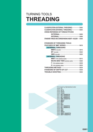
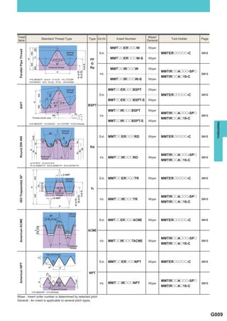
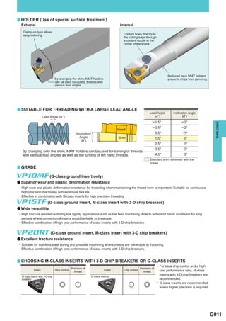
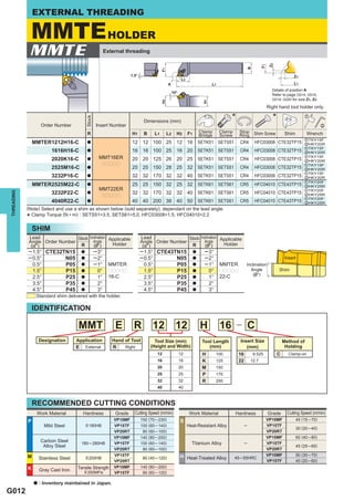
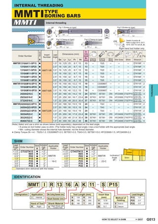
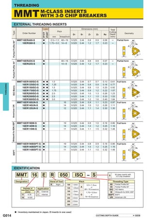
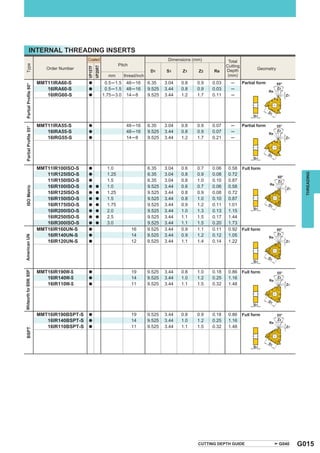
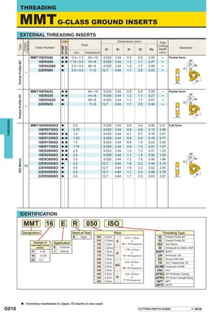
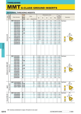
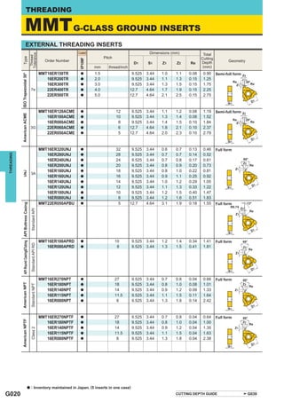
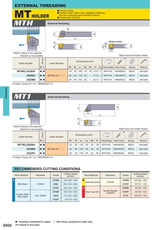
The document provides information on external threading tool holders, including the MMTE holder and MT holder. The MMTE holder uses various insert types including M-class and G-class inserts. It is available in various shank sizes and can change the lead angle by replacing a shim. The MT holder is a clamp-on type that uses precision class inserts.

![THREADING DEPTH
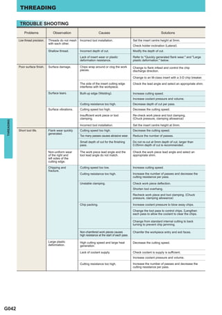
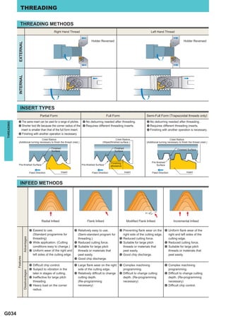
Features
Advantages Disadvantages
a Easy to use. a Long chips generated during the
(Standard programme for threading.) final pass.
a Superior resistance to vibration. a Complex calculation of cutting depth
(Constant cutting force.) when changing the number of passes.
Fixed cut area
a Reduced load on corner radius during a Subject to vibration in the later
the first half of the passes. stages of cutting.
(Increased cutting force)
a Easy chip control.
(Optional setting of chip thickness) a In some cases, changing the NC
programme is necessary.
a Easy to calculate cutting depth when
changing the number of passes.
THREADING
Fixed cutting depth a Good chip control.
pass 0.05mm ─ 0.025mm.
* Large cutting depths can the depth of cut of the final a poortosurface finish.
It is recommended to set
cause vibration, leading to
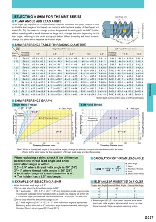
a FORMULAE
y Formulae to calculate infeed for each pass in a reduced series.
(Example)
ap External threading (ISO Metric)
]apn = × b Pitch : 1.0mm
nap ─1
ap : 0.6mm
]apn : Depth of cut nap : 5 passes
: Actual pass 0.60
n 1st Pass ]ap1 = × 0.3 = 0.16 0.16 (]ap1)
ap : Total depth of cut 5─1
: Number of passes 0.60
nap 2st Pass ]ap2 = × 2─1 = 0.3 0.14 (]ap2 ─ ]ap1)
b : 1st pass 0.3 5─1
2nd pass 2 ─ 1 = 1 0.60
3st Pass ]ap3 = × 3─1 = 0.42 0.12 (]ap3 ─ ]ap2 )
3rd pass 3 ─ 1 = 2 5─1
• 0.60
4st Pass ]ap4 = × 4─1 = 0.52 0.1 (]ap4 ─ ]ap3)
• 5─1
nth pass n ─ 1 0.60
5st Pass ]ap5 = × 5─1 = 0.6 0.08 (]ap5 ─ ]ap4)
5─1
a NC PROGRAMME FOR MODIFIED FLANK INFEED
y Example) M12×1.0 5 passes modified 5°
External Threading Internal Threading
G00 Z = 5.0 G00 Z = 5.0
X = 14.0 X = 10.0
G92 U ─ 4.34 Z ─ 13.0 F1.0 G92 U4.34 Z ─ 13.0 F1.0
G00 W ─ 0.07 G00 W ─ 0.07
G92 U ─ 4.64 Z ─ 13.0 F1.0 G92 U4.64 Z ─ 13.0 F1.0
G00 W ─ 0.06 G00 W ─ 0.05
G92 U ─ 4.88 Z ─ 13.0 F1.0 G92 U4.84 Z ─ 13.0 F1.0
G00 W ─ 0.05 G00 W ─ 0.04
G92 U ─ 5.08 Z ─ 13.0 F1.0 G92 U5.02 Z ─ 13.0 F1.0
G00 W ─ 0.03 G00 W ─ 0.03
G92 U ─ 5.20 Z ─ 13.0 F1.0 G92 U5.14 Z ─ 13.0 F1.0
G00 G00
G035](https://image.slidesharecdn.com/threading-130112060949-phpapp01/85/THREADING-36-320.jpg)
![THREADING
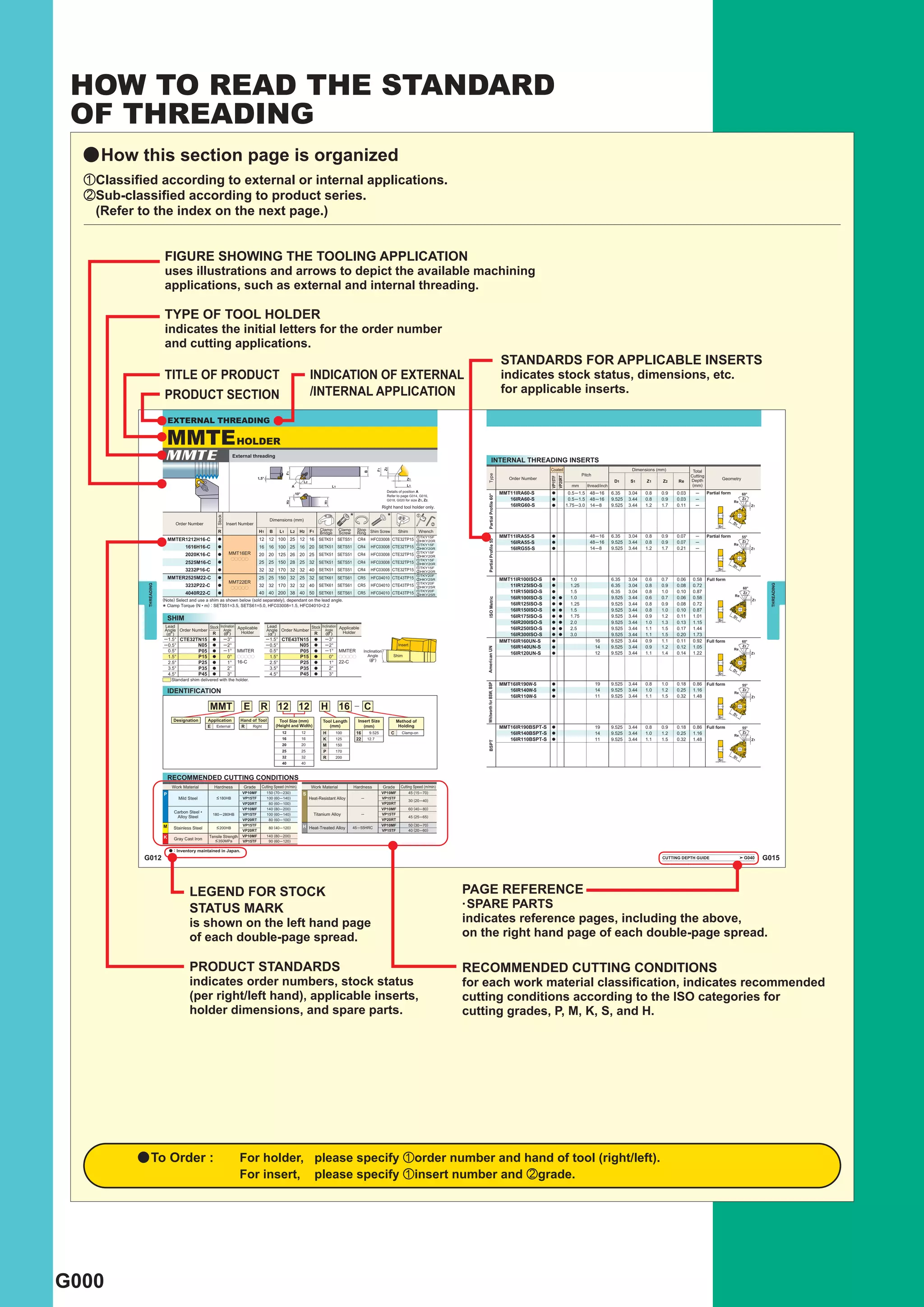
SELECTING CUTTING CONDITIONS
Priority
Efficiency
Tool Life Cutting Force Surface Finish Precision of Thread Chip Discharge (Reduced Passes)
Threading Radial u u u u
Methods Flank (] : Modified) u (] : Modified) u
Cutting Fixed Cutting Depth u
Depth Fixed Cut Area u u u u u
* Tool life and surface finish accuracy can be increased by changing the threading method from flank infeed to modified flank infeed.
* Chip control can be improved by increasing the cutting depth in the later half of passes.
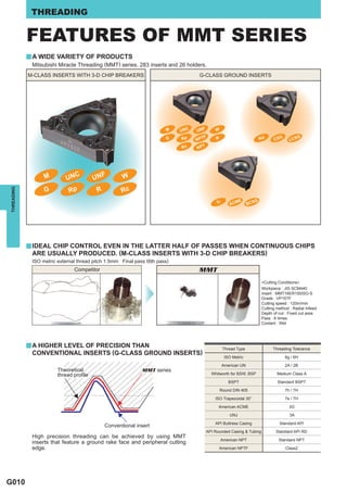
CUTTING DEPTH AND THE NUMBER OF PASSES FEATURES AND BENEFITS OF MITSUBISHI PRODUCTS
y Selection of the appropriate cutting depth • Insert grades with high wear and plastic deformation
resistance, specially produced for threading tools, ensure
and the right number of passes is vital for
highly efficient cutting by enabling high-speed machining
threading.
and a reduced number of passes.
• For most threading, use a "threading cycle program,"
which has originally been installed on machines, and
THREADING
specify "total cutting depth" and "cutting depth in the first
or final pass."
• Cutting depth and the number of passes are easy to
change for the radial infeed method, thus making it easy Machining Cost
to determine the appropriate cutting conditions.
Reduction
ADVICE ON IMPROVED THREADING
y Increasing tool life y Preventing vibration
• To prevent damage to the corner radius - • Change to flank or modified infeed.
Recommended method - Modified flank infeed • When using radial infeed, reduce cutting depth in the later
• To have uniform flank wear on both sides of a cutting edge - half of passes and lower the cutting speed.
Recommended method - Radial infeed
• To prevent crater wear -
Recommended method - Flank infeed
y Increased surface finish accuracy
• A final wiping pass should be performed at the same depth
of cut as the last regular pass.
y Preventing chip problems • When using the flank infeed method, change to radial
• Change to flank or modified infeed. infeed only during the final pass.
• During radial infeed cutting, use an inverted holder and
change the coolant supply to a downward direction.
• When using the radial infeed method, set the minimum
cutting depth at around 0.2mm to make the chips thicker.
y To achieve highly efficient machining
• Increase cutting speed. (Dependant on the maximum
revolution and rigidity of the machine.)
• Reduce the number of passes. (Reduce by 30-40%.)
• A reduced number of passes can improve chip discharge
because of the thicker chips generated.
G036](https://image.slidesharecdn.com/threading-130112060949-phpapp01/85/THREADING-37-320.jpg)