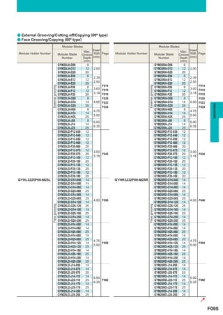
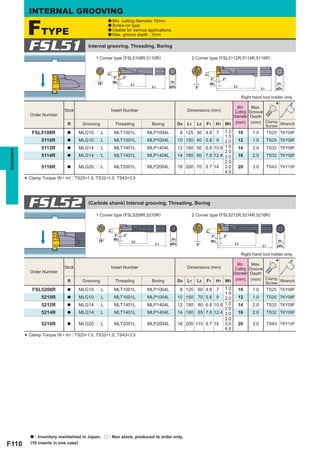
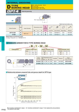
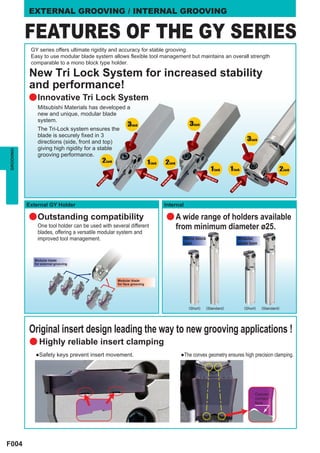
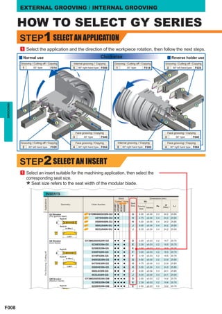
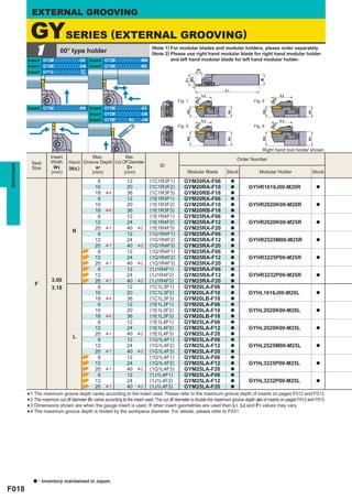
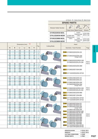
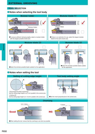
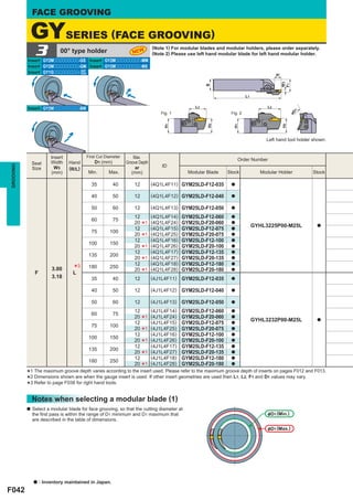
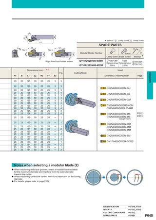
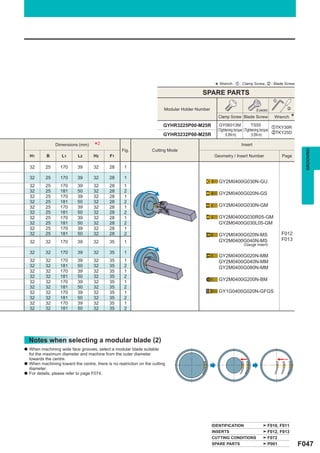
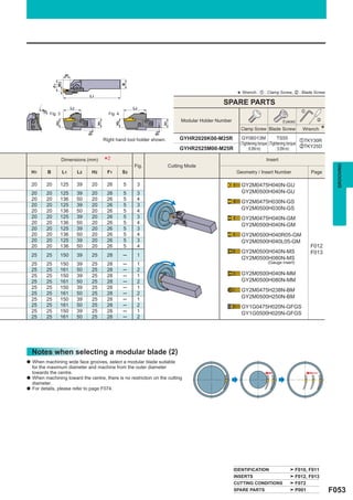
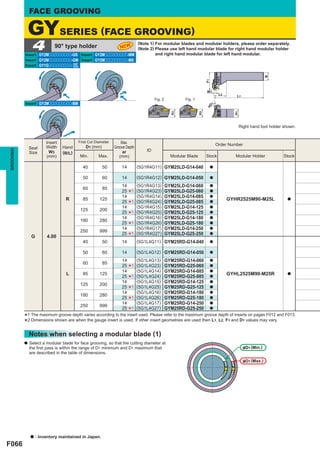
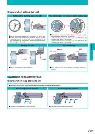
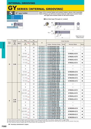
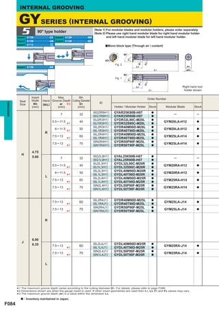
This document provides information on how to read the standard for grooving. It is organized by external and internal grooving applications and further classified by product series. For external grooving, it indicates holder types and available machining applications through illustrations and arrows. Product sections show the geometry and features for different external grooving inserts. For internal grooving, it provides the minimum cutting diameter, holder type as either corner or geometry type, and specifications for each type.
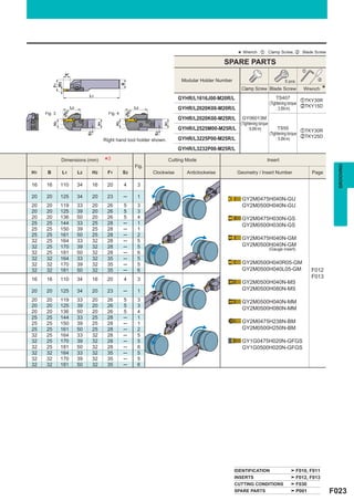
![HOW TO READ THE STANDARD
OF GROOVING
aHow this section page is organized
zClassified according to external or internal applications.
xSub-classified according to product series.
(Refer to the index on the next page.)
[For External Grooving] [For Internal Grooving]
FIGURE SHOWING THE TOOLING APPLICATION
uses illustrations and arrows to depict available machining MIN. CUTTING
applications such as cutting off, grooving, and copying. DIAMETER
INDICATION OF HOLDER TYPE ACCORDING TO APPLICATION is colour-coded to let
indicates the holder types, such as the standard type or the L type, you find, at a glance,
according to machining application. the minimum cutting
TITLE OF PRODUCT PRODUCT FEATURES diameters for internal
INDICATION OF EXTERNAL/
machining.
PRODUCT SECTION FACE GROOVING/INTERNAL
APPLICATION GEOMETRY
EXTERNAL GROOVING INTERNAL GROOVING
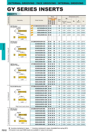
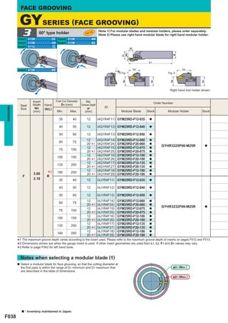
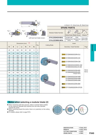
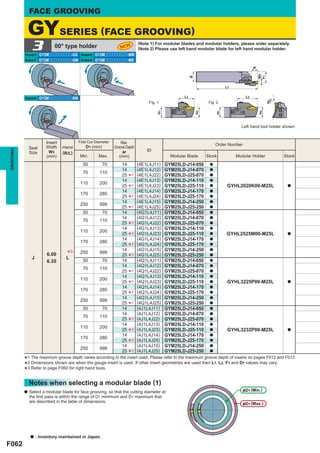
GYSERIES (EXTERNAL GROOVING) FTYPE
a Min. cutting diameter 10mm
a Screw-on type
a Usable for various applications.
a Max. groove depth : 3mm
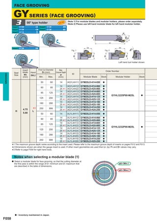
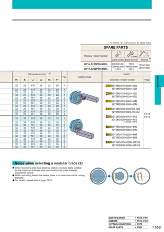
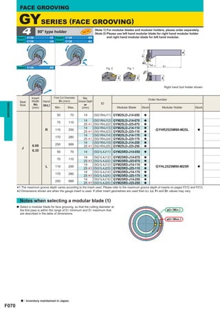
1 00° type holder
Insert GY2Mooooooooo-GS Insert GY2Mooooooooo-GS
(Note 1) For modular blades and modular holders, please order separately.
(Note 2) Please use right hand modular blade for right hand modular holder
and left hand modular blade for left hand modular holder.
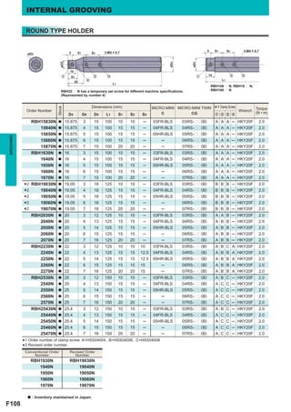
FSL51 Internal grooving, Threading, Boring
Insert GY2Mooooooooo-GM Insert GY2Mooooooooo-GM 1 Corner type (FSL5108R,5110R) 2 Corner type (FSL5112R,5114R,5116R)
ar
Insert GY1Gooooooooo- GF Insert GY2MoooooR/Loo-GM
GS
W3
F1
B
F1
F1
2° 2° 2° 2°
L1 W3 H1 H1
10° L2 W3
L2 L2 L1 øD4 5° L2
1 1 L1 øD4
Fig. 1 øD Fig. 2 øD
Right hand tool holder only.
H2
H2
H1
H1
L2 L2 Stock Insert Number Dimensions (mm)
Min. Max. *
1 1 Cutting Groove
Fig. 5 øD Fig. 6 øD Order Number Diameter Depth
R Grooving Threading Boring D4 L1 L2 F1 H1 W3 (mm) (mm) Clamp Wrench
H2
H2
H1
H1
Screw
FSL5108R a MLG10ppL MLT1001L MLP1004L 8 125 30 4.8 7 1.2 10 1.0 TS25 TKY08F
Right hand tool holder shown. 1.5
Insert Max. Max.
5110R a MLG10ppL MLT1001L MLP1004L 10 150 40 5.8 9 2.0 12 1.0 TS25 TKY08F
Order Number
Seat Width Hand Groove Depth Cut Off Diameter 5112R a MLG14ppL MLT1401L MLP1404L 12 180 50 6.8 10.8 1.5 14 2.0 TS32 TKY08F
GROOVING
GROOVING
W3 ar D1 ID 2.0
Size (R/L)
(mm) (mm) (mm) Modular Blade Stock Modular Holder Stock 5114R a MLG14ppL MLT1401L MLP1404L 14 180 60 7.8 12.4 3.0 16 2.0 TS32 TKY08F
(1C1R3E1) a
2.0
6 12 GYM20RA-E06 5116R a MLG20ppL MLT2001L MLP2004L 16 200 70 9.7 14 3.0 20 3.0 TS43 TKY15F
10 20 (1C1R3E2) GYM20RA-E10 a GYHR1616J00-M20R a
4.0
18 36 (1C1R3E3) GYM20RB-E18 a
6
*4 12 (1E1R3E1) GYM20RA-E06 a * Clamp Torque (N • m) : TS25=1.0, TS32=1.0, TS43=3.5
10 20 (1E1R3E2) GYM20RA-E10 a GYHR2020K00-M20R a
18 4 36 (1E1R3E3) GYM20RB-E18 a
*
FSL52
6 12 (1E1R4E1) GYM25RA-E06 a
12 24 (1E1R4E2) GYM25RA-E12 a GYHR2020K00-M25R a (Carbide shank) Internal grooving, Threading, Boring
20 40 (1E1R4E3) GYM25RA-E20 a
R
6
*1 12
*2 (1G1R4E1) GYM25RA-E06 a
1 Corner type (FSL5208R,5210R) 2 Corner type (FSL5212R,5214R,5216R)
12 24 (1G1R4E2) GYM25RA-E12 a GYHR2525M00-M25R a
20 40 (1G1R4E3) GYM25RA-E20 a
6
*1 12
*2 (1Q1R4E1) GYM25RA-E06 a
F1
F1
12 24 (1Q1R4E2) GYM25RA-E12 a GYHR3225P00-M25R a
2° 2° 2° 2°
20 40 (1Q1R4E3) GYM25RA-E20 a
6
*1 12
*2 (1J1R4E1) GYM25RA-E06 a
10° W3
L2
L1
H1
øD4 5°
W3
L2
L1
H1
øD4
12 24 (1J1R4E2) GYM25RA-E12 a GYHR3232P00-M25R a
2.39 20 40 (1J1R4E3) GYM25RA-E20 a Right hand tool holder only.
E
6
*1 12
*2 (1C1L3E1) GYM20LA-E06 a
2.50
10 20 (1C1L3E2) GYM20LA-E10 a GYHL1616J00-M20L a
Stock Insert Number Dimensions (mm)
Min. Max. *
(1C1L3E3) a
Cutting Groove
18 36 GYM20LB-E18
6
*4 12 (1E1L3E1) GYM20LA-E06 a
Order Number Diameter Depth
Clamp
10 20 (1E1L3E2) GYM20LA-E10 a GYHL2020K00-M20L a R Grooving Threading Boring D4 L1 L2 F1 H1 W3 (mm) (mm) Screw Wrench
18 4 36 (1E1L3E3) GYM20LB-E18 a
6
* 12 (1E1L4E1) GYM25LA-E06 a
FSL5208R a MLG10ppL MLT1001L MLP1004L 8 125 60 4.8 7 1.2
1.5
10 1.0 TS25 TKY08F
12 24 (1E1L4E2) GYM25LA-E12 a GYHL2020K00-M25L a 5210R a MLG10ppL MLT1001L MLP1004L 10 150 70 5.8 9 2.0 12 1.0 TS25 TKY08F
20 40 (1E1L4E3) GYM25LA-E20 a
L
6
*1 12
*2 (1G1L4E1) GYM25LA-E06 a
5212R a MLG14ppL MLT1401L MLP1404L 12 180 80 6.8 10.8 1.5
2.0
14 2.0 TS32 TKY08F
12 24 (1G1L4E2) GYM25LA-E12 a GYHL2525M00-M25L a 5214R a MLG14ppL MLT1401L MLP1404L 14 180 85 7.8 12.4 3.0 16 2.0 TS32 TKY08F
20 1 40 2 (1G1L4E3) GYM25LA-E20 a 2.0
6
* 12
* (1Q1L4E1) GYM25LA-E06 a 5216R a MLG20ppL MLT2001L MLP2004L 16 200 115 9.7 14 3.0 20 3.0 TS43 TKY15F
12 24 (1Q1L4E2) GYM25LA-E12 a GYHL3225P00-M25L a 4.0
(1Q1L4E3)
20
6
*1 40
12
*2 (1J1L4E1)
GYM25LA-E20
GYM25LA-E06
a
a
* Clamp Torque (N • m) : TS25=1.0, TS32=1.0, TS43=3.5
12 24 (1J1L4E2) GYM25LA-E12 a GYHL3232P00-M25L a
20 40 (1J1L4E3) GYM25LA-E20 a
*1 *2
*2 The maximum cutgroove depth1varies according to to the insert used.cut off diameter is double the maximum groove depth (ar) of insertspages F012 and F013.
1 The maximum according Please refer to the maximum groove depth of inserts on
*3 Dimensions shown are whenvariesgauge insert isinsert used.other insert geometries are used then L1, L2 and F1 values maypages F012 and F013.
off diameter D
the
the
used. If
The on
vary.
*4 The maximum groove depth is limited by the workpiece diameter. For details, please refer to F031.
*
a : Inventory maintained in Japan. a : Inventory maintained in Japan. r : Non stock, produced to order only.
(10 inserts in one case)
F016 F110
PRODUCT STANDARDS LEGEND FOR
indicates order numbers, stock status STOCK STATUS MARK
(per right/left hand), holders, Modular Blade, is shown on the left hand
groove widths, maximum groove depths, page of each double-page
maximum cut-off diameters, dimensions, spread.
applicable inserts, and cutting edge shapes.
a To Order : For holder, please specify zorder number and hand of tool (right/left).
For insert, please specify zinsert number and xgrade.
F000](https://image.slidesharecdn.com/grooving-130112060920-phpapp01/85/GROOVING-1-320.jpg)
![HOW TO READ THE STANDARD
OF GROOVING
aHow this section page is organized
zClassified according to external or internal applications.
xSub-classified according to product series.
(Refer to the index on the next page.)
[For External Grooving] [For Internal Grooving]
FIGURE SHOWING THE TOOLING APPLICATION
uses illustrations and arrows to depict available machining MIN. CUTTING
applications such as cutting off, grooving, and copying. DIAMETER
INDICATION OF HOLDER TYPE ACCORDING TO APPLICATION is colour-coded to let
indicates the holder types, such as the standard type or the L type, you find, at a glance,
according to machining application. the minimum cutting
TITLE OF PRODUCT PRODUCT FEATURES diameters for internal
INDICATION OF EXTERNAL/
machining.
PRODUCT SECTION FACE GROOVING/INTERNAL
APPLICATION GEOMETRY
EXTERNAL GROOVING INTERNAL GROOVING
GYSERIES (EXTERNAL GROOVING) FTYPE
a Min. cutting diameter 10mm
a Screw-on type
a Usable for various applications.
a Max. groove depth : 3mm
1 00° type holder
Insert GY2Mooooooooo-GS Insert GY2Mooooooooo-GS
(Note 1) For modular blades and modular holders, please order separately.
(Note 2) Please use right hand modular blade for right hand modular holder
and left hand modular blade for left hand modular holder.
FSL51 Internal grooving, Threading, Boring
Insert GY2Mooooooooo-GM Insert GY2Mooooooooo-GM 1 Corner type (FSL5108R,5110R) 2 Corner type (FSL5112R,5114R,5116R)
ar
Insert GY1Gooooooooo- GF Insert GY2MoooooR/Loo-GM
GS
W3
F1
B
F1
F1
2° 2° 2° 2°
L1 W3 H1 H1
10° L2 W3
L2 L2 L1 øD4 5° L2
1 1 L1 øD4
Fig. 1 øD Fig. 2 øD
Right hand tool holder only.
H2
H2
H1
H1
L2 L2 Stock Insert Number Dimensions (mm)
Min. Max. *
1 1 Cutting Groove
Fig. 5 øD Fig. 6 øD Order Number Diameter Depth
R Grooving Threading Boring D4 L1 L2 F1 H1 W3 (mm) (mm) Clamp Wrench
H2
H2
H1
H1
Screw
FSL5108R a MLG10ppL MLT1001L MLP1004L 8 125 30 4.8 7 1.2 10 1.0 TS25 TKY08F
Right hand tool holder shown. 1.5
Insert Max. Max.
5110R a MLG10ppL MLT1001L MLP1004L 10 150 40 5.8 9 2.0 12 1.0 TS25 TKY08F
Order Number
Seat Width Hand Groove Depth Cut Off Diameter 5112R a MLG14ppL MLT1401L MLP1404L 12 180 50 6.8 10.8 1.5 14 2.0 TS32 TKY08F
GROOVING
GROOVING
W3 ar D1 ID 2.0
Size (R/L)
(mm) (mm) (mm) Modular Blade Stock Modular Holder Stock 5114R a MLG14ppL MLT1401L MLP1404L 14 180 60 7.8 12.4 3.0 16 2.0 TS32 TKY08F
(1C1R3E1) a
2.0
6 12 GYM20RA-E06 5116R a MLG20ppL MLT2001L MLP2004L 16 200 70 9.7 14 3.0 20 3.0 TS43 TKY15F
10 20 (1C1R3E2) GYM20RA-E10 a GYHR1616J00-M20R a
4.0
18 36 (1C1R3E3) GYM20RB-E18 a
6
*4 12 (1E1R3E1) GYM20RA-E06 a * Clamp Torque (N • m) : TS25=1.0, TS32=1.0, TS43=3.5
10 20 (1E1R3E2) GYM20RA-E10 a GYHR2020K00-M20R a
18 4 36 (1E1R3E3) GYM20RB-E18 a
*
FSL52
6 12 (1E1R4E1) GYM25RA-E06 a
12 24 (1E1R4E2) GYM25RA-E12 a GYHR2020K00-M25R a (Carbide shank) Internal grooving, Threading, Boring
20 40 (1E1R4E3) GYM25RA-E20 a
R
6
*1 12
*2 (1G1R4E1) GYM25RA-E06 a
1 Corner type (FSL5208R,5210R) 2 Corner type (FSL5212R,5214R,5216R)
12 24 (1G1R4E2) GYM25RA-E12 a GYHR2525M00-M25R a
20 40 (1G1R4E3) GYM25RA-E20 a
6
*1 12
*2 (1Q1R4E1) GYM25RA-E06 a
F1
F1
12 24 (1Q1R4E2) GYM25RA-E12 a GYHR3225P00-M25R a
2° 2° 2° 2°
20 40 (1Q1R4E3) GYM25RA-E20 a
6
*1 12
*2 (1J1R4E1) GYM25RA-E06 a
10° W3
L2
L1
H1
øD4 5°
W3
L2
L1
H1
øD4
12 24 (1J1R4E2) GYM25RA-E12 a GYHR3232P00-M25R a
2.39 20 40 (1J1R4E3) GYM25RA-E20 a Right hand tool holder only.
E
6
*1 12
*2 (1C1L3E1) GYM20LA-E06 a
2.50
10 20 (1C1L3E2) GYM20LA-E10 a GYHL1616J00-M20L a
Stock Insert Number Dimensions (mm)
Min. Max. *
(1C1L3E3) a
Cutting Groove
18 36 GYM20LB-E18
6
*4 12 (1E1L3E1) GYM20LA-E06 a
Order Number Diameter Depth
Clamp
10 20 (1E1L3E2) GYM20LA-E10 a GYHL2020K00-M20L a R Grooving Threading Boring D4 L1 L2 F1 H1 W3 (mm) (mm) Screw Wrench
18 4 36 (1E1L3E3) GYM20LB-E18 a
6
* 12 (1E1L4E1) GYM25LA-E06 a
FSL5208R a MLG10ppL MLT1001L MLP1004L 8 125 60 4.8 7 1.2
1.5
10 1.0 TS25 TKY08F
12 24 (1E1L4E2) GYM25LA-E12 a GYHL2020K00-M25L a 5210R a MLG10ppL MLT1001L MLP1004L 10 150 70 5.8 9 2.0 12 1.0 TS25 TKY08F
20 40 (1E1L4E3) GYM25LA-E20 a
L
6
*1 12
*2 (1G1L4E1) GYM25LA-E06 a
5212R a MLG14ppL MLT1401L MLP1404L 12 180 80 6.8 10.8 1.5
2.0
14 2.0 TS32 TKY08F
12 24 (1G1L4E2) GYM25LA-E12 a GYHL2525M00-M25L a 5214R a MLG14ppL MLT1401L MLP1404L 14 180 85 7.8 12.4 3.0 16 2.0 TS32 TKY08F
20 1 40 2 (1G1L4E3) GYM25LA-E20 a 2.0
6
* 12
* (1Q1L4E1) GYM25LA-E06 a 5216R a MLG20ppL MLT2001L MLP2004L 16 200 115 9.7 14 3.0 20 3.0 TS43 TKY15F
12 24 (1Q1L4E2) GYM25LA-E12 a GYHL3225P00-M25L a 4.0
(1Q1L4E3)
20
6
*1 40
12
*2 (1J1L4E1)
GYM25LA-E20
GYM25LA-E06
a
a
* Clamp Torque (N • m) : TS25=1.0, TS32=1.0, TS43=3.5
12 24 (1J1L4E2) GYM25LA-E12 a GYHL3232P00-M25L a
20 40 (1J1L4E3) GYM25LA-E20 a
*1 *2
*2 The maximum cutgroove depth1varies according to to the insert used.cut off diameter is double the maximum groove depth (ar) of insertspages F012 and F013.
1 The maximum according Please refer to the maximum groove depth of inserts on
*3 Dimensions shown are whenvariesgauge insert isinsert used.other insert geometries are used then L1, L2 and F1 values maypages F012 and F013.
off diameter D
the
the
used. If
The on
vary.
*4 The maximum groove depth is limited by the workpiece diameter. For details, please refer to F031.
*
a : Inventory maintained in Japan. a : Inventory maintained in Japan. r : Non stock, produced to order only.
(10 inserts in one case)
F016 F110
PRODUCT STANDARDS LEGEND FOR
indicates order numbers, stock status STOCK STATUS MARK
(per right/left hand), holders, Modular Blade, is shown on the left hand
groove widths, maximum groove depths, page of each double-page
maximum cut-off diameters, dimensions, spread.
applicable inserts, and cutting edge shapes.
a To Order : For holder, please specify zorder number and hand of tool (right/left).
For insert, please specify zinsert number and xgrade.
F000](https://image.slidesharecdn.com/grooving-130112060920-phpapp01/75/GROOVING-1-2048.jpg)

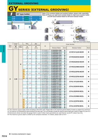


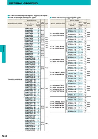
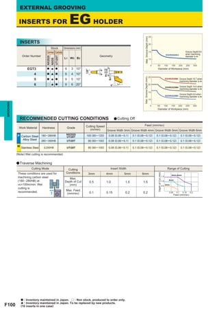
![EXTERNAL GROOVING
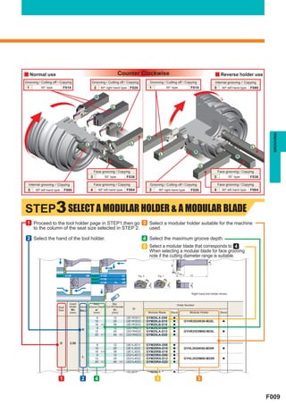
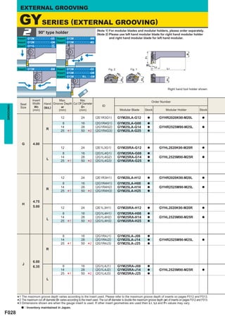
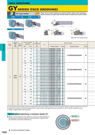
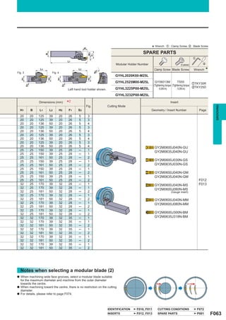
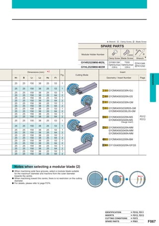
RECOMMENDED CUTTING CONDITIONS [For External Grooving] *the modular holder GYHR/L2525M00-M25R/L with the
Below are the recommended cutting conditions when using
modular blade GYM25oA-oo.
y Recommended feed rate and depth of cut
GU BREAKER GS BREAKER GM BREAKER FLAT TOP GFGS (CBN)
a Grooving, Cutting off a Grooving, Cutting off a Grooving, Cutting off a Grooving
6.35 6.35 6.35
6.0 6.0 6.0
5.0 5.0
Insert width (mm)
Insert width (mm)
Insert width (mm)
Insert width (mm)
5.0 5.0
4.75 4.75 4.75 4.75
4.0 4.0 4.0 4.0
3.18 3.18 3.18
3.0 3.0 3.0
2.5 2.5 2.5
2.39 2.39 2.39
2.0 2.0 2.0
0 0.05 0.1 0.2 0 0.05 0.1 0.2 0.3 0 0.1 0.2 0.3 0.4 0 0.05 0.1 0.15
Feed (mm/rev) Feed (mm/rev) Feed (mm/rev) Feed (mm/rev)
: 1st recommended area
MS BREAKER
a Grooving a Turning
GROOVING
: 1st 4.0
Radial Depth of cut (mm)
recommended area
6.0
Insert width 6mm
Insert width (mm)
3.0
5.0 Insert width 5mm
Insert width 4mm
2.0
4.0
3.0 1.0
Insert width 3mm
0 0.1 0.2 0.3 0.4 0 0.1 0.2 0.3 0.4
Feed (mm/rev) Feed (mm/rev)
MM BREAKER
a Grooving a Turning
: 1st 4.0
Radial Depth of cut (mm)
6.0 recommended area
Insert width 6mm
Insert width (mm)
5.0 3.0 Insert width 5mm
4.0 Insert width 4mm
2.0
3.0 Insert width
3mm
2.5
1.0
2.0 Insert width 2.5mm
Insert width 2mm
0 0.1 0.2 0.3 0.4 0 0.1 0.2 0.3 0.4
Feed (mm/rev) Feed (mm/rev)
BM BREAKER
a Grooving a Turning
6.35 : 1st 4.0
6.0
Radial Depth of cut (mm)
recommended area
Insert width
5.0
Insert width (mm)
5.0mm
4.75 3.0 4.75mm Insert width
Insert width 6.35mm
4.0 4.0mm
6.0mm
3.18 2.0
3.0 Insert width
3.18mm
2.5 3.0mm
Insert width
1.0 2.5mm
2.0 Insert width
2.0mm
0 0.1 0.2 0.3 0.4 0 0.1 0.2 0.3 0.4 0.5 0.6 0.7 0.8
Feed (mm/rev) Feed (mm/rev)
(Note) When using a combination as shown below, decrease the recommended feed rate by 20% and 40% respectively.
a Decrease the feed rate by 20%. a Decrease the feed rate by 40%.
20mm
20mm
16mm
GYHR2020K00-M25R GYHR2020K00-M20R GYHR1616J00-M20R
GYM25 GYM20 GYM20
(20mm×20mm Square holder) (16mm×16mm Square holder)
F030](https://image.slidesharecdn.com/grooving-130112060920-phpapp01/85/GROOVING-31-320.jpg)
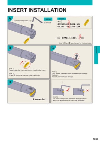
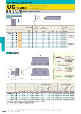
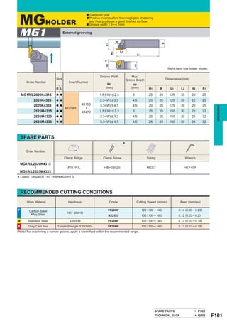
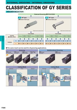
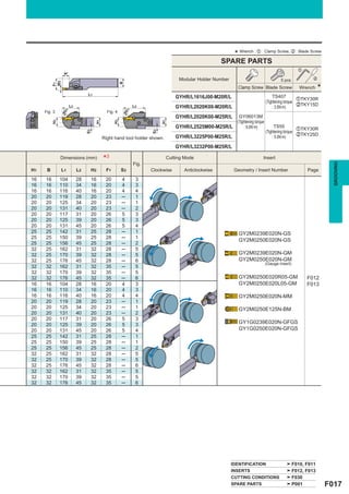
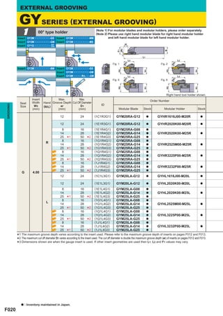
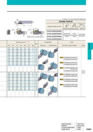
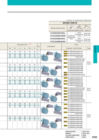
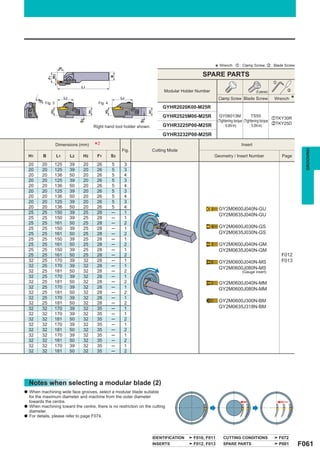
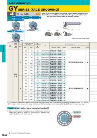
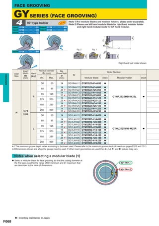
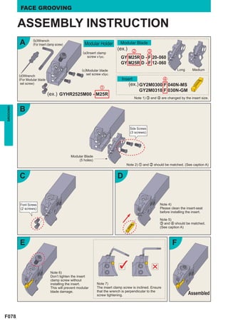
![ASSEMBLY INSTRUCTION
A (b)Wrench
(For Insert clamp screw) Modular Holder Modular Blade
(ex.) x c
(a)Insert clamp
screw x1pc. GY M25R A - F 20
GY M25R A - F 12 Short,
Long Medium
(c)Modular blade (5 holes) (4 holes)
(d)Wrench set screw x5pc.
(For Modular blade Insert v
set screw) (ex.) GY2M0300 F 040N-MS
z
GY2M0318 F 030N-GM
(ex.) GYHR2525M00 - M25R
Note 1) c and v are changed by the insert size.
B
GROOVING
B'
Side Screws
(3 screws) Side Screws
(2 screws)
Short, Medium
Modular Blade
Long (4 holes)
Modular Blade
(5 holes)
Note 2) z and x should be matched. (See caption A)
C D
Front Screws Note 4)
(2 screws) Please clean the insert-seat
before installing the insert.
Note 3)
Note 5)
Please tighten the modular blade
c and v should be matched.
set screws in order of
(See caption A)
[Side screws] → [Front screws].
E F
Note 6)
Don’t tighten the insert
clamp screw without
installing the insert. Note 7)
This will prevent modular The insert clamp screw is inclined. Ensure
blade damage. that the wrench is perpendicular to the
screw tightening. Assembled
F035](https://image.slidesharecdn.com/grooving-130112060920-phpapp01/85/GROOVING-36-320.jpg)


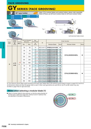
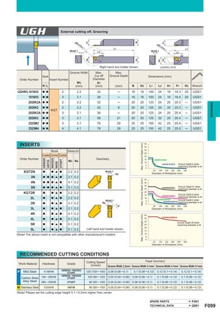
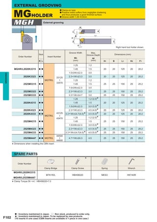
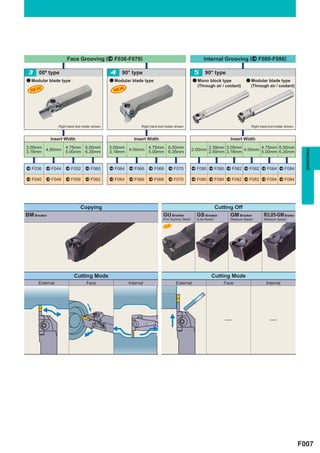
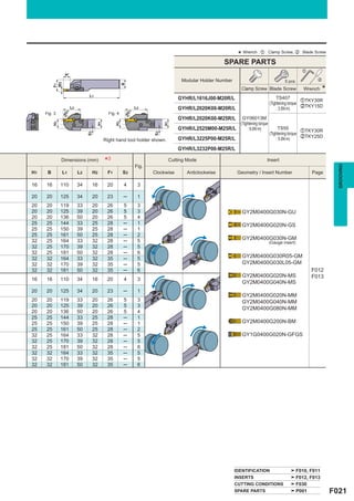
![FACE GROOVING
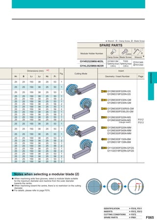
RECOMMENDED CUTTING CONDITIONS [Face Grooving]
GROOVING
: 1st
6.35 recommended area
6.0
Insert width (mm)
5.0
4.75
4.0
3.18
3.0
0 0.05 0.1 0.15 0.2
Feed (mm/rev)
PLUNGING
: 1st
6.35 recommended area
GROOVING
6.0
Insert width (mm)
5.0
4.75
4.0
3.18
3.0
0 0.05 0.10
Feed (mm/rev)
0.15 0.20 0.25
* set narrower plunge, the with Wof. cut should be
After the 1st
than insert
width
3
TRAVERSE MACHINING (MM/MS BREAKER)
3.0
Insert width 6mm
Axial Depth of Cut (mm)
Insert width 5mm
2.0
Insert width 4mm
1.0
Insert width 3mm
0 0.1 0.2 0.3
Feed (mm/rev)
TRAVERSE MACHINING (BM BREAKER)
3.0
Axial Depth of Cut (mm)
2.0 Insert width 6mm,6.35mm
Insert width
4.75mm,5mm
Insert width
1.0 4mm
Insert width 3mm,3.18mm
0 0.2 0.4 0.6
Feed (mm/rev)
F072](https://image.slidesharecdn.com/grooving-130112060920-phpapp01/85/GROOVING-73-320.jpg)

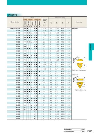
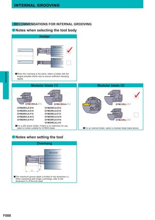
![INTERNAL GROOVING
RECOMMENDED CUTTING CONDITIONS [For Internal Grooving]
GROOVING
(Note 1) The cutting diameter 100% represents the minimum cutting diameter (øD1).
(Note 2) The graph on the left shows the cutting conditions when setting the feed to 100%.
105
: 1st
Shank Diameter D4 (mm)
50 recommended area
100
40
Feed (%)
95
32
90
25
20 85
80
0 0.05 0.1 0.15 0.2 100 150 200 250
Feed (mm/rev) Hole diameter (%)
TRAVERSE MACHINING (MM/MS BREAKER)
a When traverse machining a blind hole, it is recommended to
GROOVING
4.0
carry out back turning considering chip disposal.
Radial Depth of cut (mm)
Insert width 6mm
3.0
Insert width 5mm
Insert width 4mm
2.0
Insert width 3mm
1.0
Insert Width 2.5mm
Insert Width 2mm
0 0.1 0.2 0.3
Feed (mm/rev)
(Note) The above cutting conditions are for when using the tool overhang (L) 1.6-2.0 times larger than the shank diameter (øD4). (L/D=1.6-2.0)
When using L/D larger than 2.0, reduce the cutting conditions.
Tool chuck
&D4
L
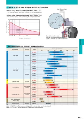
LIMITATION OF THE MAXIMUM GROOVE DEPTH
●When using the mono block type
The maximum groove depth is not limited by the cutting diameter.
●When using the modular blade type
The maximum groove depth is limited by the cutting diameter.
Due to interference of this part,
the maximum groove depth is
limited by the cutting diameter.
•Shank Diameter=32mm (GYM20 Blade) • Shank Diameter=40mm (GYM20 Blade)
12 12
11.5 11.5
11 11
GYM20L/RA-G12 GYM20L/RA-G12
10 GYM20L/RA-H12 GYM20L/RA-H12
Max. Groove Depth (mm)
Max. Groove Depth (mm)
10
9
9
8
8
7 GYM20L/RA-D10
GYM20L/RA-D10 7 GYM20L/RA-E10
6 GYM20L/RA-E10 GYM20L/RA-F10
GYM20L/RA-F10
6
5
4.5 5.5
4 5
40 44 55 65 80 90 105 y 50 56 65 80 100 110 130 y
41 48 54
Workpiece Diameter (mm) Workpiece Diameter (mm)
F086](https://image.slidesharecdn.com/grooving-130112060920-phpapp01/85/GROOVING-87-320.jpg)
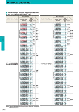
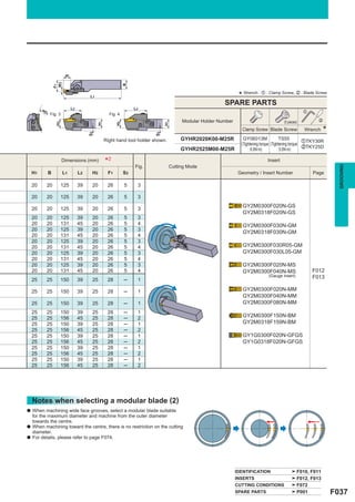
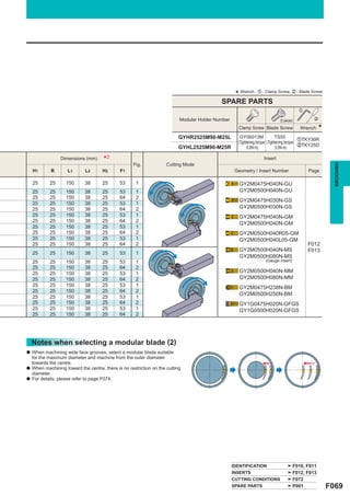
![INTERNAL GROOVING
ASSEMBLY INSTRUCTION
A (a)Insert clamp
screw x1pc.
Modular Holder Modular Blade
(d)Wrench x c
(For Modular blade (ex.) GY M20R A - F 10
set screw) Short,
GY M25R A - F 12 Medium
(4 holes)
(b)Wrench
(c)Modular blade (For Insert Insert v
clamp screw)
set screw x4pc. (ex.) GY2M0300 F 040N-MS
z
(ex.) GYDL40M90D - M20R GY2M0318 F 030N-GM
GYDL40M90D - M25R Note 1) c and v are changed by the insert size.
B C
GROOVING
Side Screws
(2 screws)
Note 3)
Please tighten the modular blade Front Screws
Note 2) set screws in order of (2 screws)
z and x should be matched. (See caption A) [Side screws] → [Front screws].
D Note 4)
Please clean the E
insert-seat before
installing the insert.
Note 5)
c and v should be
matched.
(See caption A) Note 6)
Don’t tighten the insert clamp screw without installing
the insert.
F This will prevent modular blade damage.
Note 7)
The insert clamp screw is inclined. Ensure that the
Assembled wrench is perpendicular to the screw tightening.
F090](https://image.slidesharecdn.com/grooving-130112060920-phpapp01/85/GROOVING-91-320.jpg)