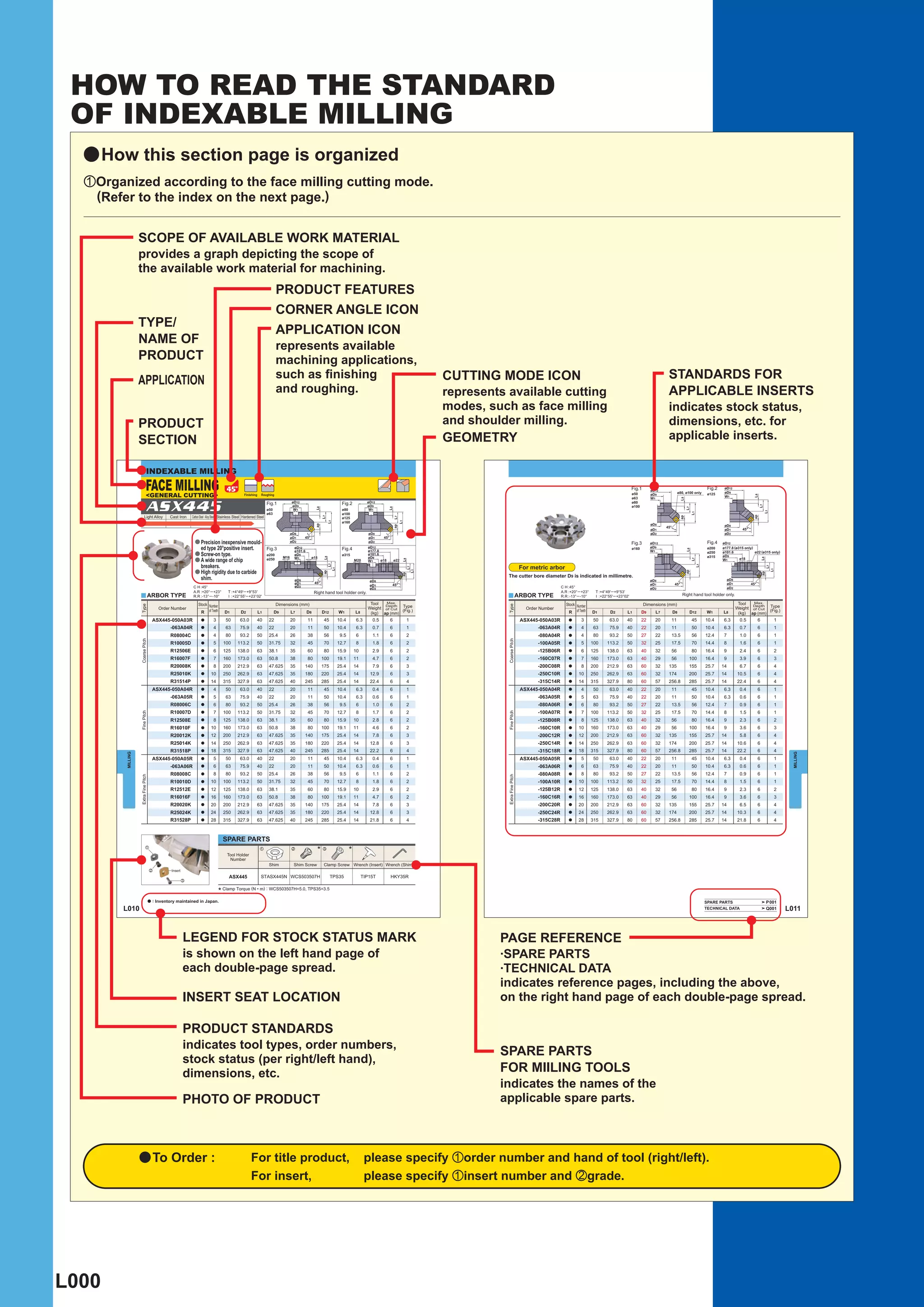
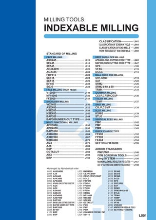
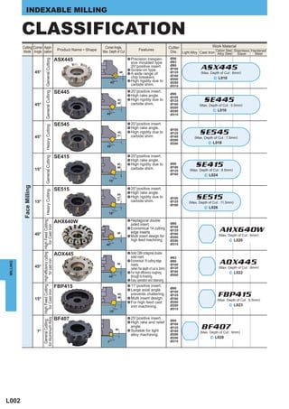
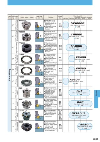
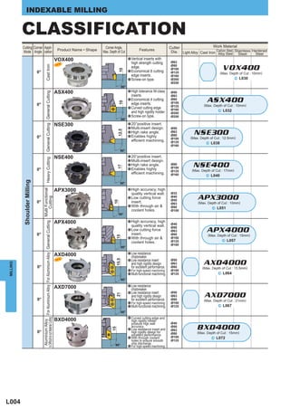
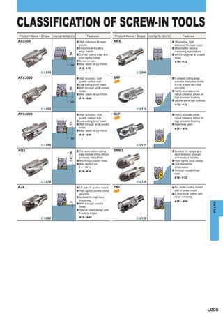
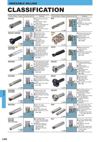
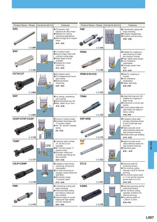
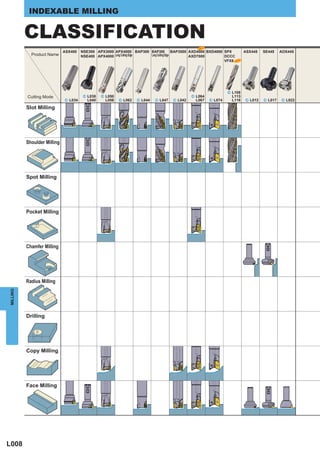
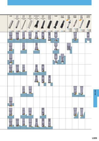
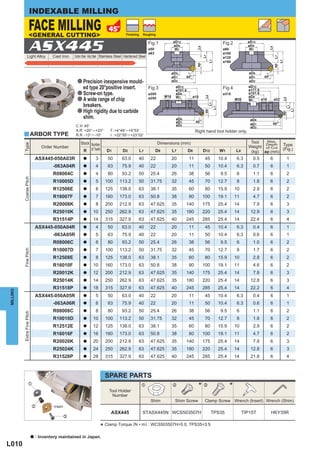
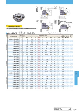
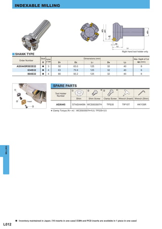
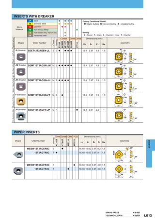
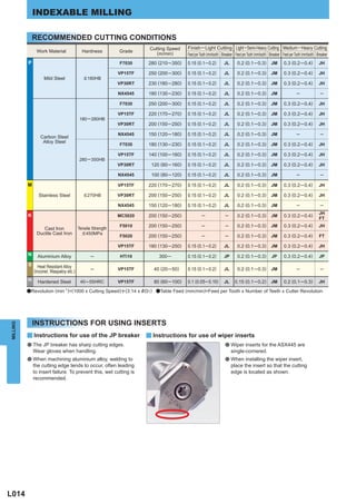
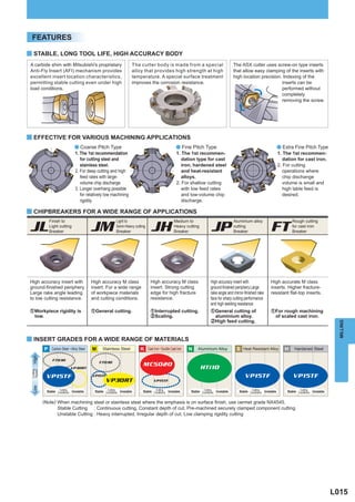
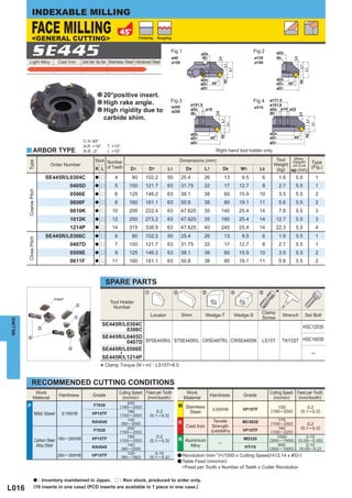
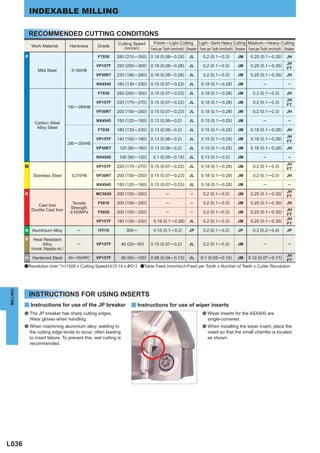
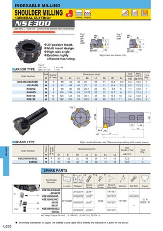
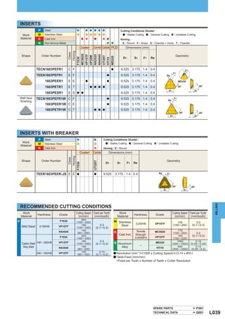
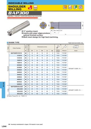
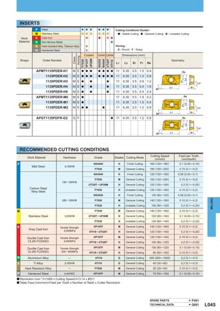
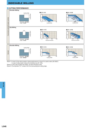
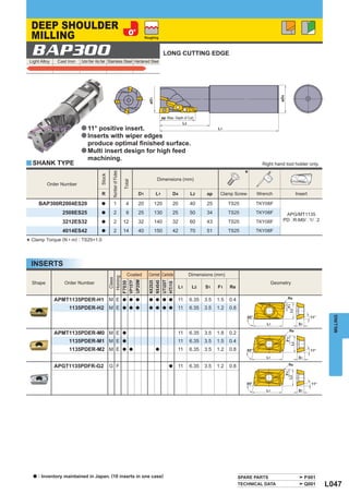
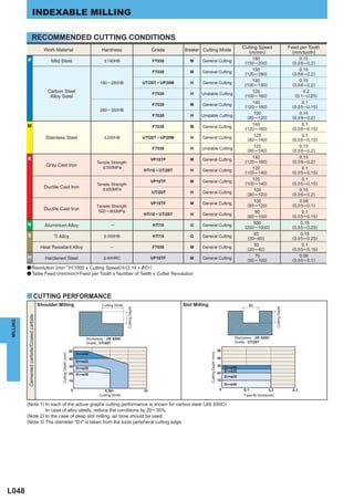
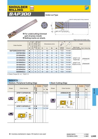
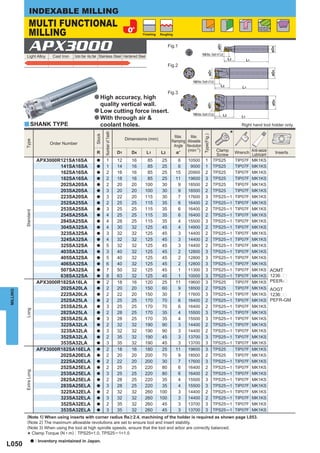
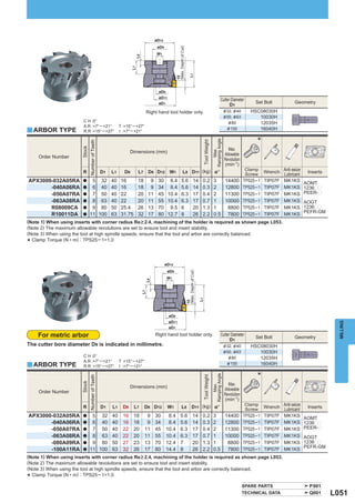
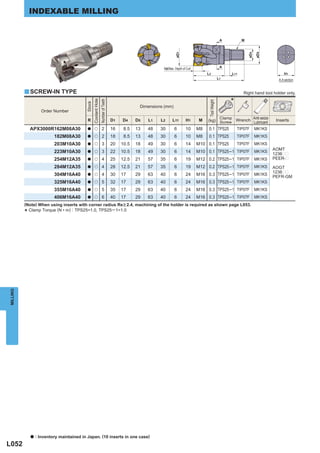
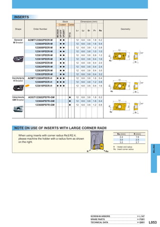
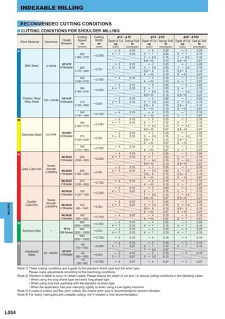
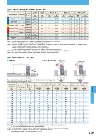
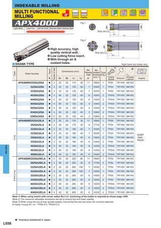
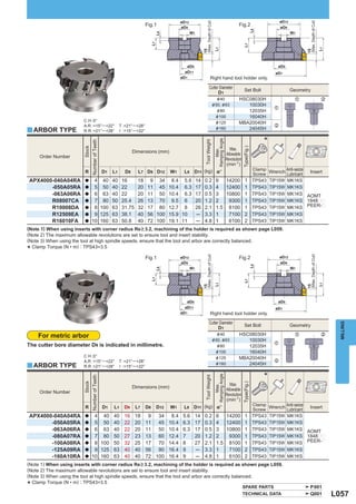
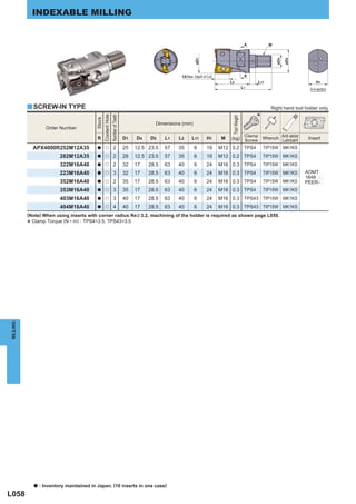
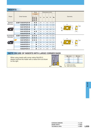
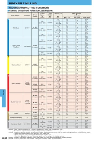
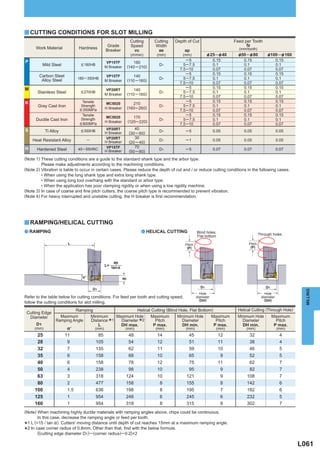
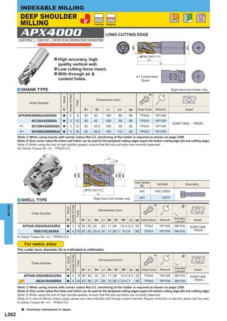
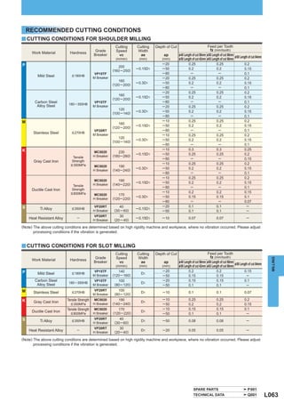
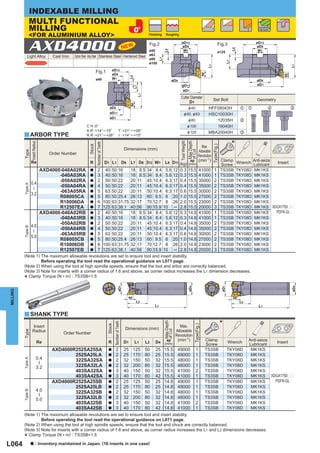
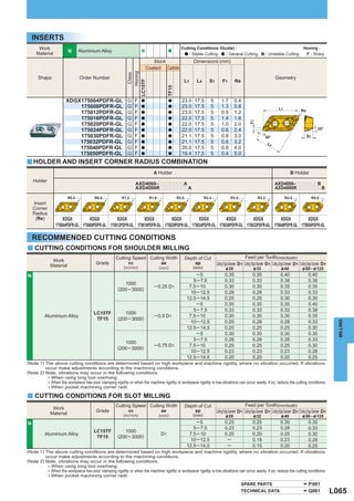
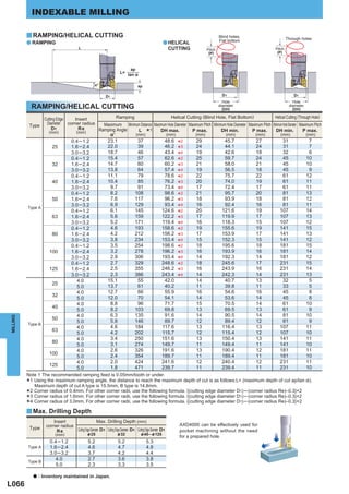
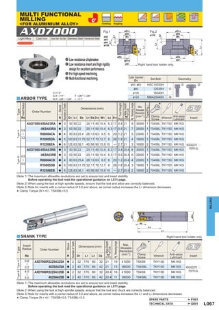
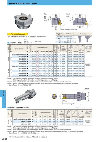
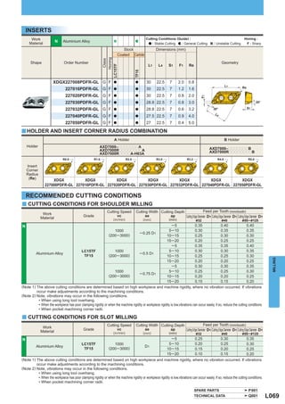
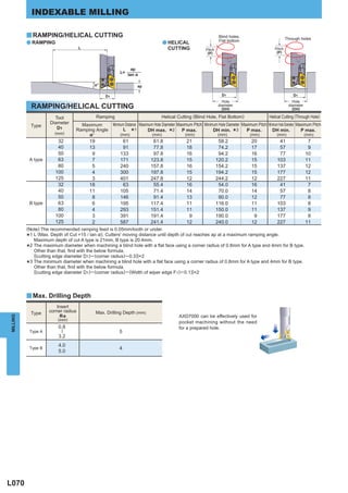
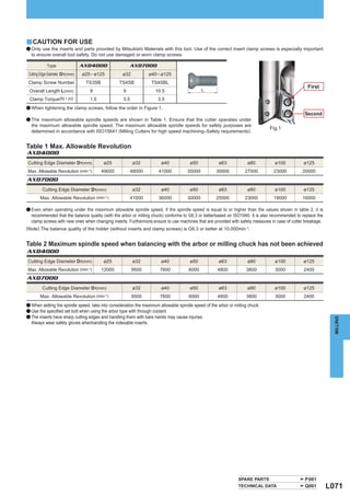
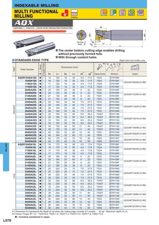
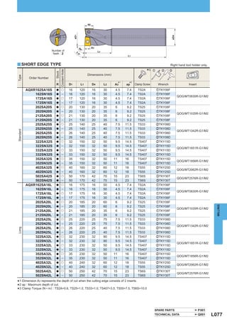
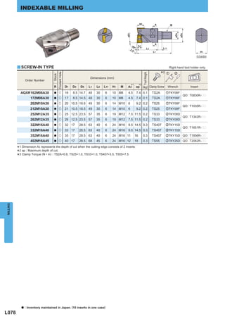
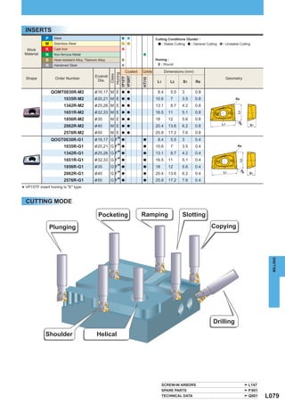
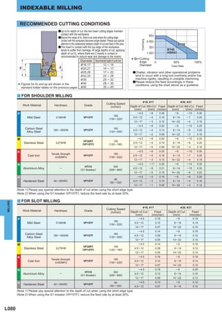
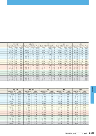
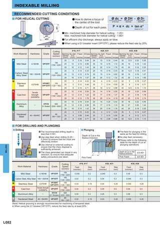
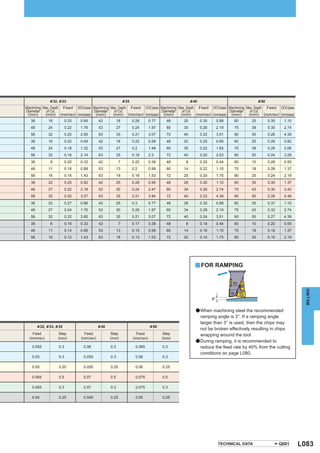
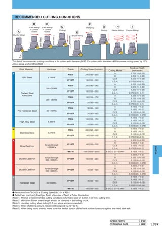
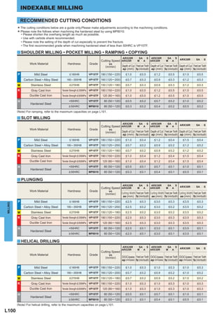
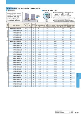
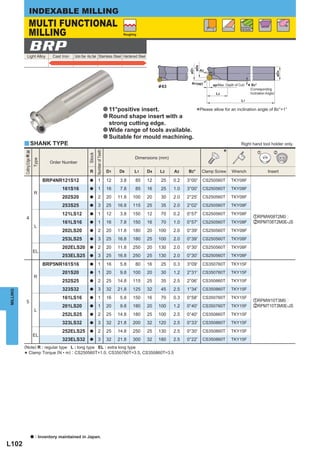
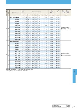
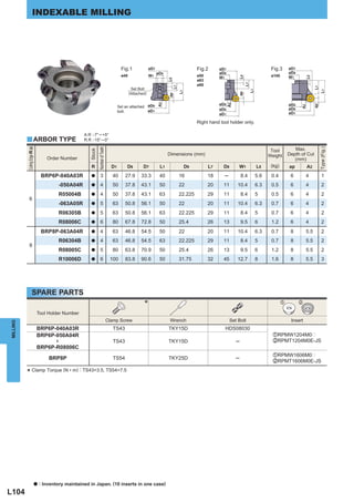
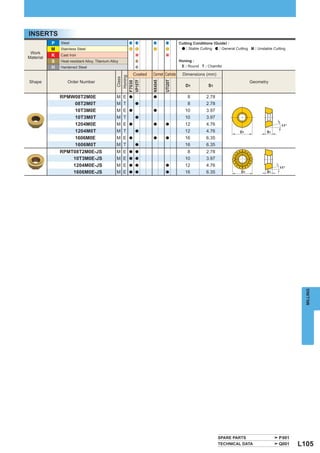
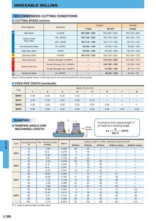
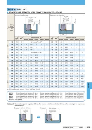
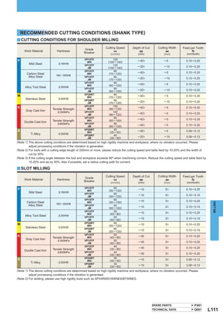
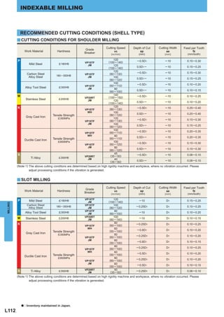
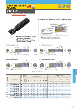
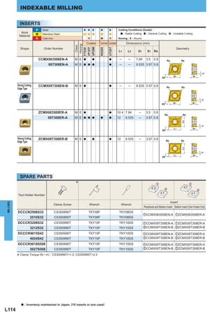
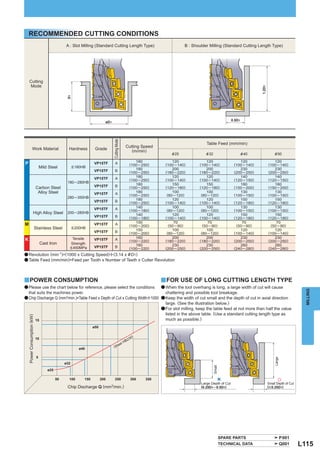
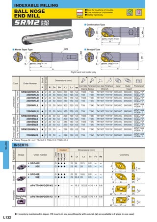
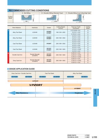
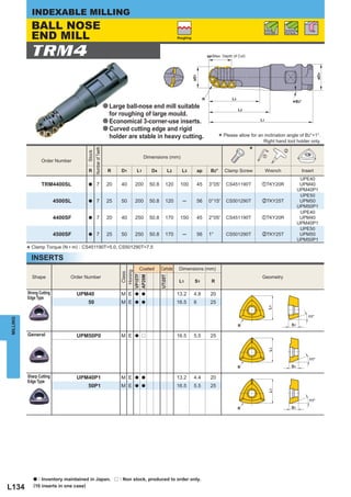
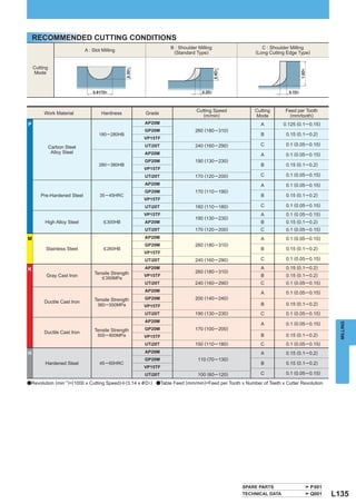
HOW TO READ THE STANDARD
 OF INDEXABLE MILLING
  a How this section page is organized
  zOrganized according to the face milling cutting mode.
   (Refer to the index on the next page.)


                   SCOPE OF AVAILABLE WORK MATERIAL
                   provides a graph depicting the scope of
                   the available work material for machining.
                                                                                                                                   PRODUCT FEATURES
                                                                                                                                   CORNER ANGLE ICON
                   TYPE/
                                                                                                                                   APPLICATION ICON
                   NAME OF                                                                                                         represents available
                   PRODUCT                                                                                                         machining applications,
                   APPLICATION                                                                                                     such as finishing                                                                                            CUTTING MODE ICON                                                                                              STANDARDS FOR
                                                                                                                                   and roughing.                                                                                               represents available cutting                                                                                   APPLICABLE INSERTS
                                                                                                                                                                                                                                               modes, such as face milling                                                                                    indicates stock status,
                   PRODUCT                                                                                                                                                                                                                     and shoulder milling.                                                                                          dimensions, etc. for
                   SECTION                                                                                                                                                                                                                     GEOMETRY                                                                                                       applicable inserts.

                                INDEXABLE MILLING

                               FACE MILLING
                               <GENERAL CUTTING>                                                         Finishing    Roughing
                                                                                                                                                                                                                                                                                                                                          Fig.1
                                                                                                                                                                                                                                                                                                                                          ø50
                                                                                                                                                                                                                                                                                                                                                      øD12
                                                                                                                                                                                                                                                                                                                                                      øD9
                                                                                                                                                                                                                                                                                                                                                                    ø80, ø100 only
                                                                                                                                                                                                                                                                                                                                                                                              Fig.2
                                                                                                                                                                                                                                                                                                                                                                                              ø125
                                                                                                                                                                                                                                                                                                                                                                                                       øD12
                                                                                                                                                                                                                                                                                                                                                                                                       øD9


                                                                                                                                                                                                                                                                                                                                                                                                                            L8
                                                                                                                                                                                                                                                                                                                                          ø63                                                          W1


                                                                                                                                                                                                                                                                                                                                                                         L8
                                                                                                                                                                                                                                                                                                                                                      W1


                               ASX445                                                                                       Fig.1            øD12                                    Fig.2           øD12                                                                                                                                 ø80


                                                                                                                                                                                                                                                                                                                                                                                                                                 L7
                                                                                                                                             øD9                                                     øD9                                                                                                                                  ø100
                                                                                                                                                              L8


                                                                                                                                                                                                                                                                                                                                                                              L7
                                                                                                                                                                                                                   L8


                                                                                                                            ø50               W1                                     ø80              W1


                                                                                                                                                                                                                                                                                                                                                                                                                                      L1
                                                                                                                                                                                                                                                                                                                                                                                   L1
                                                                                                                            ø63                                                      ø100


                                                                                                                                                                                                                                                                                                                                                                                                                            ap
                                                                                                                                                                   L7


                         Light Alloy              Cast Iron     Carbon Steel · Alloy Steel Stainless Steel Hardened Steel


                                                                                                                                                                                                                                                                                                                                                                         ap
                                                                                                                                                                                                                        L7


                                                                                                                                                                                     ø125
                                                                                                                                                                         L1


                                                                                                                                                                                                                              L1


                                                                                                                                                                                     ø160
                                                                                                                                                                                                                                                                                                                                                      øD8
                                                                                                                                                              ap


                                                                                                                                                                                                                        ap


                                                                                                                                                                                                                                                                                                                                                             45°                                       øD8
                                                                                                                                                                                                                                                                                                                                                      øD1                                              øD1          45°
                                                                                                                                             øD8                                                      øD8                                                                                                                                             øD2                                              øD2
                                                                                                                                             øD1     45°                                              øD1    45°
                                                                  a Precision inexpensive mould-                                             øD2                                                      øD2                                                                                                                                 Fig.3       øD12                                    Fig.4   øD12
                                                                    ed type 20°positive insert.                             Fig.3              øD12                                  Fig.4           øD12                                                                                                                                 ø160        øD9                                     ø200    ø177.8 (ø315 only)


                                                                                                                                                                                                                                                                                                                                                                              L8
                                                                                                                                               ø101.6                                                ø177.8                                                                                                                                           W1                                                                 ø22 (ø315 only)
                                                                  a Screw-on type.                                          ø200               øD9                                   ø315            ø101.6                                                                                                                                                                                   ø250
                                                                                                                                                                                                                                                                                                                                                                                              ø315
                                                                                                                                                                                                                                                                                                                                                                                                      ø101.6
                                                                                                                                                                                                                                                                                                                                                                                                      øD9
                                                                                                                                                                    L8


                                                                                                                                       M16                 ø18                                       øD9


                                                                                                                                                                                                                                                                                                                                                                                                                                    L8
                                                                                                                                               W1
                                                                  a A wide range of chip                                                                                                                                                                                                                                                                                                                        ø18


                                                                                                                                                                                                                                                                                                                                                                                   L7
                                                                                                                            ø250
                                                                                                                                                                                                                                   L8


                                                                                                                                                                                              M20    W1     ø18         ø22                                                                                                                                                                           W1
                                                                                                                                                                         L7


                                                                                                                                                                                                                                                                                                                                                                                        L1
                                                                    breakers.


                                                                                                                                                                                                                                                                                                                                                                                                                                           L7
                                                                                                                                                                                                                                                                             For metric arbor
                                                                                                                                                                                                                                          L7
                                                                                                                                                                              L1


                                                                                                                                                                                                                                                                                                                                                                                                                                         L1
                                                                  a High rigidity due to carbide
                                                                                                                                                                                                                                        L1


                                                                                                                                                                                                                                                                                                                                                                              ap
                                                                                                                                                                   ap


                                                                                                                                                                                                                                                                                                                                                                                                                                    ap
                                                                                                                                                                                                                               ap


                                                                                                                                                                                                                                                          The cutter bore diameter D9 is indicated in millimetre.
                                                                    shim.                                                                      øD8                                                    øD8                                                                                                                                             øD8                                                  øD8
                                                                                                                                               øD1           45°                                                                                                                                                                                      øD1          45°                                     øD1            45°
                                                                                                                                               øD2                                                    øD1           45°
                                                                 C H :45°                                                                                                                             øD2                                                                                      C H :45°                                               øD2                                                  øD2
                                                                 A.R :+20° ─ +23°           T :+4°49′─ +9°53′                                                Right hand tool holder only.                                                                                                      A.R :+20° ─ +23°    T :+4°49′─ +9°53′
                   y ARBOR TYPE                                  R.R :-13° ─ -10°           I :+22°55′ ─ +23°02′                                                                                                                                          y ARBOR TYPE                         R.R :-13° ─ -10°    I :+22°55′ ─ +23°02′                                  Right hand tool holder only.

                                                                                                                                                                                                      Tool  Max.                                                                                                                                                                                                  Tool  Max.
                                                                    Stock Number                                                   Dimensions (mm)                                                                                                                                               Stock Number                                     Dimensions (mm)
                   Type


                                                                                                                                                                                                                                                          Type


                                                                                                                                                                                                     Weight of Cut Type                                                                                                                                                                                          Weight of Cut Type
                                                                                                                                                                                                            Depth                                                                                                                                                                                                       Depth
                                            Order Number                                                                                                                                                           (Fig.)                                                      Order Number                                                                                                                                    (Fig.)
                                                                     R of Teeth          D1           D2             L1           D9         L7         D8         D12             W1         L8      (kg) ap (mm)                                                                                R of Teeth      D1       D2         L1         D9     L7         D8          D12           W1       L8          (kg) ap (mm)
                                          ASX445-050A03R               a        3         50          63.0         40        22              20         11         45              10.4       6.3      0.5         6                1                                        ASX445-050A03R        a      3        50      63.0      40          22     20     11                  45        10.4     6.3          0.5          6           1
                                                  -063A04R             a        4         63          75.9         40        22              20         11         50              10.4       6.3      0.7         6                1                                               -063A04R       a      4        63      75.9      40          22     20     11                  50        10.4     6.3          0.7          6           1
                                                  R08004C              a        4         80          93.2         50        25.4            26         38          56              9.5        6       1.1         6                2                                               -080A04R       a      4        80      93.2      50          27     22     13.5                56        12.4     7            1.0          6           1
                   Coarse Pitch


                                                                                                                                                                                                                                                          Coarse Pitch


                                                  R10005D              a        5       100         113.2          50        31.75           32         45          70             12.7        8       1.8         6                2                                               -100A05R       a      5       100    113.2       50          32     25     17.5                70        14.4     8            1.6          6           1
                                                  R12506E              a        6       125         138.0          63        38.1            35         60          80             15.9       10       2.9         6                2                                               -125B06R       a      6       125    138.0       63          40     32     56                  80        16.4     9            2.4          6           2
                                                  R16007F              a        7       160         173.0          63        50.8            38         80         100             19.1       11       4.7         6                2                                               -160C07R       a      7       160    173.0       63          40     29     56              100           16.4     9            3.9          6           3
                                                  R20008K              a        8       200         212.9          63        47.625          35      140           175             25.4       14       7.9         6                3                                               -200C08R       a      8       200    212.9       63          60     32    135              155           25.7     14           6.7          6           4
                                                  R25010K              a      10        250         262.9          63        47.625          35      180           220             25.4       14      12.9         6                3                                               -250C10R       a     10       250    262.9       63          60     32    174              200           25.7     14         10.5           6           4
                                                  R31514P              a      14        315         327.9          63        47.625          40      245           285             25.4       14      22.4         6                4                                               -315C14R       a     14       315    327.9       80          60     57    256.8            285           25.7     14         22.4           6           4
                                          ASX445-050A04R               a        4         50          63.0         40        22              20         11         45              10.4       6.3      0.4         6                1                                        ASX445-050A04R        a      4        50      63.0      40          22     20     11                  45        10.4     6.3          0.4          6           1
                                                  -063A05R             a        5         63          75.9         40        22              20         11         50              10.4       6.3      0.6         6                1                                               -063A05R       a      5        63      75.9      40          22     20     11                  50        10.4     6.3          0.6          6           1
                                                  R08006C              a        6         80          93.2         50        25.4            26         38          56              9.5        6       1.0         6                2                                               -080A06R       a      6        80      93.2      50          27     22     13.5                56        12.4     7            0.9          6           1
                   Fine Pitch


                                                                                                                                                                                                                                                          Fine Pitch


                                                  R10007D              a        7       100         113.2          50        31.75           32         45          70             12.7        8       1.7         6                2                                               -100A07R       a      7       100    113.2       50          32     25     17.5                70        14.4     8            1.5          6           1
                                                  R12508E              a        8       125         138.0          63        38.1            35         60          80             15.9       10       2.8         6                2                                               -125B08R       a      8       125    138.0       63          40     32     56                  80        16.4     9            2.3          6           2
                                                  R16010F              a      10        160         173.0          63        50.8            38         80         100             19.1       11       4.6         6                2                                               -160C10R       a     10       160    173.0       63          40     29     56              100           16.4     9            3.6          6           3
                                                  R20012K              a      12        200         212.9          63        47.625          35      140           175             25.4       14       7.8         6                3                                               -200C12R       a     12       200    212.9       63          60     32    135              155           25.7     14           5.8          6           4
                                                  R25014K              a      14        250         262.9          63        47.625          35      180           220             25.4       14      12.8         6                3                                               -250C14R       a     14       250    262.9       63          60     32    174              200           25.7     14         10.6           6           4
                                                  R31518P              a      18        315         327.9          63        47.625          40      245           285             25.4       14      22.2         6                4                                               -315C18R       a     18       315    327.9       80          60     57    256.8            285           25.7     14         22.2           6           4
         MILLING


                                                                                                                                                                                                                                                                                                                                                                                                                                                   MILLING
                                          ASX445-050A05R               a        5         50          63.0         40        22              20         11         45              10.4       6.3      0.4         6                1                                        ASX445-050A05R        a      5        50      63.0      40          22     20     11                  45        10.4     6.3          0.4          6           1
                                                  -063A06R             a        6         63          75.9         40        22              20         11         50              10.4       6.3      0.6         6                1                                               -063A06R       a      6        63      75.9      40          22     20     11                  50        10.4     6.3          0.6          6           1
                                                  R08008C              a        8         80          93.2         50        25.4            26         38          56              9.5        6       1.1         6                2                                               -080A08R       a      8        80      93.2      50          27     22     13.5                56        12.4     7            0.9          6           1
                   Extra Fine Pitch


                                                                                                                                                                                                                                                          Extra Fine Pitch


                                                  R10010D              a      10        100         113.2          50        31.75           32         45          70             12.7        8       1.8         6                2                                               -100A10R       a     10       100    113.2       50          32     25     17.5                70        14.4      8           1.5          6           1
                                                  R12512E              a      12        125         138.0          63        38.1            35         60          80             15.9       10       2.9         6                2                                               -125B12R       a     12       125    138.0       63          40     32     56                  80        16.4      9           2.3          6           2
                                                  R16016F              a      16        160         173.0          63        50.8            38         80         100             19.1       11       4.7         6                2                                               -160C16R       a     16       160    173.0       63          40     29     56              100           16.4     9            3.6          6           3
                                                  R20020K              a      20        200         212.9          63        47.625          35      140           175             25.4       14       7.8         6                3                                               -200C20R       a     20       200    212.9       63          60     32    135              155           25.7     14           6.5          6           4
                                                  R25024K              a      24        250         262.9          63        47.625          35      180           220             25.4       14      12.8         6                3                                               -250C24R       a     24       250    262.9       63          60     32    174              200           25.7     14         10.3           6           4
                                                  R31528P              a      28        315         327.9          63        47.625          40      245           285             25.4       14      21.8         6                4                                               -315C28R       a     28       315    327.9       80          60     57    256.8            285           25.7     14         21.8           6           4


                                                                                        SPARE PARTS
                             z
                                                                                           Tool Holder
                                                                                                                      z                      x
                                                                                                                                                              *c                          *
                                                                                            Number
                                                                                                                             Shim             Shim Screw           Clamp Screw Wrench (Insert) Wrench (Shim)
                                      x            Insert
                                                                                             ASX445                   STASX445N WCS503507H                               TPS35                     TIP15T          HKY35R
                                                            c


                                                                                    * Clamp Torque (N • m) : WCS503507H=5.0, TPS35=3.5
                                      a   : Inventory maintained in Japan.                                                                                                                                                                                                                                                                                                                   SPARE PARTS                                 P 001
        L010                                                                                                                                                                                                                                                                                                                                                                                 TECHNICAL DATA                              Q001    L011


                                                            LEGEND FOR STOCK STATUS MARK                                                                                                                                                                PAGE REFERENCE
                                                            is shown on the left hand page of                                                                                                                                                           ·SPARE PARTS
                                                            each double-page spread.                                                                                                                                                                    ·TECHNICAL DATA
                                                                                                                                                                                                                                                        indicates reference pages, including the above,
                                                            INSERT SEAT LOCATION                                                                                                                                                                        on the right hand page of each double-page spread.

                                                            PRODUCT STANDARDS
                                                            indicates tool types, order numbers,
                                                                                                                                                                                                                                                        SPARE PARTS
                                                            stock status (per right/left hand),
                                                            dimensions, etc.                                                                                                                                                                            FOR MIILING TOOLS
                                                                                                                                                                                                                                                        indicates the names of the
                                                            PHOTO OF PRODUCT                                                                                                                                                                            applicable spare parts.


                   a To Order :                                                                               For title product,                                                                    please specify zorder number and hand of tool (right/left).
                                                                                                              For insert,                                                                           please specify zinsert number and xgrade.


L000
MILLING TOOLS
INDEXABLE MILLING
                                                                  CLASSIFICATION................                L002
                                                                  CLASSIFICATION OF SCREW-IN TOOLS ...          L005
                                                                  CLASSIFICATION OF END MILLS ...               L006
                                                                  HOW TO SELECT AN END MILL ...                 L008
STANDARD OF MILLING
FACE MILLING                                                 DEEP SHOULDER MILLING
ASX445......................................       L010      APX4000LONG CUTTING EDGE TYPE ...                  L062
SE445 ........................................     L016      BAP300LONG CUTTING EDGE TYPE ...                   L047
SE545 ........................................     L018      SPX ............................................   L108
AHX640W ..................................         L020      VFX6 ..........................................    L116
AOX445 .....................................       L022      DCCC.........................................      L113
FBP415 ......................................      L023      BALL NOSE END MILLING
SE415 ........................................     L024      SRF,SRB ...................................        L118
SE515 ........................................     L026      SUF ............................................   L122
BF407 ........................................     L028      SRM2 .........................................     L126
SG20 ..........................................    L029      SRM2&40, &50 ..........................            L132
FACE MILLING (HIGH FEED)                                     TRM4 .........................................     L134
V10000....................................... L149           CHAMFER MILLING
NF10000 .................................... L150            CESP,CFSP,CGSP .................... L136
FF3000....................................... L151           T-SLOT MILLING
SHOULDER MILLING                                             TSMP ......................................... L137
VOX400 .....................................       L030      SPOT MILLING
ASX400......................................       L032      CBJP,CBMP .............................. L138
NSE300......................................       L038      SLOT MILLING
NSE400......................................       L040      KSMG ........................................ L139
BAP300 .....................................       L044      STLG ......................................... L141
BAP300UNDER-CUT TYPE......                         L049      VERTICAL FEED MILLING
MULTI FUNCTIONAL MILLING                                     PMC ........................................... L142
APX3000....................................        L050      PMF ........................................... L144
APX4000....................................        L056      PMR ........................................... L145
BAP3500 ...................................        L042      QUICK CHANGE TYPE
AXD4000 ...................................        L064      FP490 ........................................     L152
AXD7000 ...................................        L067      FP590 ........................................     L153
BXD4000 ...................................        L072      FE404 ........................................     L154
AQX ...........................................    L076      SETTING FIXTURE ...................                L155
AJX ............................................   L084
BSP............................................    L092      ARBOR STANDARDS
OCTACUT..................................          L094       PMF,PMR ................................          L146
ARX ...........................................    L098       FOR SCREW-IN TOOLS ........                       L147
BRP ...........................................    L102       Qing SYSTEM ........................              L156
                                                              MAXIMUM ALLOWABLE REVOLUTION FOR CUTTER ...       L157
                                                              LIST OF CUTTING EDGE DIAMETER TOLERANCES ...      L158

*Arranged by Alphabetical order BXD4000
L020 AHX640W                  L072                                           L016   SE445
 L084   AJX                              L138   CBJP,CBMP                    L026   SE515
 L022   AOX445                           L136   CESP,CFSP,CGSP               L018   SE545
 L050   APX3000                          L113   DCCC                         L029   SG20
 L056   APX4000                          L023   FBP415                       L108   SPX
 L062   APX4000 LONG CUTTING EDGE TYPE   L154   FE404                        L118   SRF,SRB
 L076   AQX                              L151   FF3000                       L122   SUF
 L098   ARX                              L152   FP490                        L126   SRM2
 L032   ASX400                           L153   FP590                        L132   SRM2& 40,& 50
 L010   ASX445                           L139   KSMG                         L141   STLG
 L064   AXD4000                          L150   NF10000                      L134   TRM4
 L067   AXD7000                          L038   NSE300                       L137   TSMP
 L044   BAP300                           L040   NSE400                       L149   V10000
 L047   BAP300 LONG CUTTING EDGE TYPE    L094   OCTACUT                      L116   VFX6
 L049   BAP300 UNDER-CUT TYPE            L142   PMC                          L030   VOX400
 L042   BAP3500                          L144   PMF                          L147   ARBORS FOR SCREW-IN TOOLS
 L028   BF407                            L145   PMR                          L155   SETTING FIXTURE
 L102   BRP                              L146   LONG ARBOR FOR PMR / PMF
 L092   BSP                              L024   SE415
                                                                                                                       L001
INDEXABLE MILLING


          CLASSIFICATION
          Cutting Corner Appli-                                                                                                          Corner Angle,                                         Cutter                    Work Material
                                                                                                                 Product Name • Shape                                Features
          Mode Angle cation                                                                                                             Max. Depth of Cut                                       Dia. Light Alloy Cast Iron CarbonSteel Stainless Hardened
                                                                                                                                                                                                                            Alloy
                                                                                                                                                                                                                                  Steel,
                                                                                                                                                                                                                                         Steel     Steel
                                                                                                                ASX445                                      a Precision  inexpen-              ·Ø50
                                                  General Cutting General Cutting


                                                                                                                                                              sive moulded type                ·Ø63

                                                                                                                                                                                                                  ASX445@)
                                                                                                                                                              20°positive insert.              ·Ø80
                                                                                                                                                            a Screw-on type.                   ·Ø100
                          45°                                                                                                                                                                  ·Ø125              (Max. Depth of Cut : 6mm


                                                                                                                                                    6
                                                                                                                                                            a A wide range of
                                                                                                                                                                                               ·Ø160
                                                                                                                                                              chip breakers.                   ·Ø200                      ^ L010
                                                                                                                                             45°            a High rigidity due to
                                                                                                                                                                                               ·Ø250
                                                                                                                                                              carbide shim.                    ·Ø315

                                                                                                                SE445                                       a 20°positive insert.
                                                                                                                                                                                               ·Ø80
                                                                                                                                                            a High rake angle.
                                                                                                                                                                                               ·Ø100
                                                                                                                                                            a High rigidity due to
                                                                                                                                                                                                                    SE445@

                                                                                                                                                   5.5
                                                                                                                                                                                               ·Ø125
                          45°                                                                                                                                 carbide shim.                    ·Ø160             (Max. Depth of Cut : 5.5mm)
                                                                                                                                                                                               ·Ø200
                                                                                                                                                                                               ·Ø250                      ^ L016
                                                                                                                                           45°                                                 ·Ø315


                                                                                                                SE545                                       a 20°positive insert.
                                                  Heavy Cutting


                                                                                                                                                            a High rake angle.
                                                                                                                                                                                               ·Ø100
                                                                                                                                                            a High rigidity due to
                                                                                                                                                                                                                 SE545@
                                                                                                                                                   7.5


                                                                                                                                                                                               ·Ø125
                          45°                                                                                                                                 carbide shim.                    ·Ø160          (Max. Depth of Cut : 7.5mm)
                                                                                                                                                                                               ·Ø200
                                                                                                                                                                                               ·Ø250                   ^ L018
                                                                                                                                           45°


                                                                                                                SE415                                       a 20°positive insert.
                                                  General Cutting


                                                                                                                                                            a High rake angle.
                                                                                                                                                            a High rigidity due to             ·Ø80
                                                                                                                                                                                                               SE415@
                                                                                                                                                   8.5


                                                                                                                                                              carbide shim.                    ·Ø100
                          15°                                                                                                                                                                  ·Ø125       (Max. Depth of Cut : 8.5mm)
                                                                                                                                                                                               ·Ø160               ^ L024
                                                                                                                                            15°
           Face Milling


                                                                                                                SE515                                       a 20°positive insert.
                                                  Heavy Cutting


                                                                                                                                                            a High rake angle.
                                                                                                                                                                                                               SE515@
                                                                                                                                                   11.5


                                                                                                                                                            a High rigidity due to             ·Ø100
                          15°                                                                                                                                 carbide shim.                    ·Ø125       (Max. Depth of Cut : 11.5mm)
                                                                                                                                                                                               ·Ø160
                                                                                                                                                                                                                    ^ L026
                                                                                                                                            15°

                                                                                                                AHX640W                                     a Heptagonal    double
                                  General Cutting High Feed Cutting High efficiency cutting High Feed Cutting


                                                                                                                                                              sided insert.                    ·Ø80
                                                                                               for Cast Iron


                                                                                                                                                                                               ·Ø100

                          40°
                                                                                                                                                            a Economical 14 cutting
                                                                                                                                                              edge inserts.
                                                                                                                                                                                               ·Ø125                          AHX640W
                                                                                                                                                   6


                                                                                                                                                                                               ·Ø160                         (Max. Depth of Cut : 6mm)
                                                                                                                                                            a Multi insert design for          ·Ø200
                                                                                                                                                              high feed machining.             ·Ø250                                ^ L020
                                                                                                                                          40°                                                  ·Ø315


                                                                                                                AOX445                                      a Solid CBN octagonal double
                                                                                                                                                              sided insert.                    ·Ø63
                                                                                                                                                                                                                              AOX445
                                                                         for cast iron


                                                                                                                                                            a Economical 16 cutting edge       ·Ø80
MILLING


                                                                                                                                                              inserts.
                                                                                                                                                   8


                                                                                                                                                                                               ·Ø100
                          45°                                                                                                                                 (when the depth of cut is 3mm)   ·Ø125                         (Max. Depth of Cut : 8mm)
                                                                                                                                                            a For high efficiency roughing     ·Ø160                                ^ L022
                                                                                                                                                                                               ·Ø200
                                                                                                                                            45°               through to finishing.
                                                                                                                                                            a Easy operation and cleansing.

                                                                                                                FBP415                                      a 11°positive insert.
                                                                                                                                                                                               ·Ø80
                                                                                                                                                            a Large axial angle
                                                     for Cast Iron


                                                                                                                                                                                               ·Ø100
                                                                                                                                                              prevents chattering.
                                                                                                                                                                                                                             FBP415@
                                                                                                                                                   8.5


                                                                                                                                                                                               ·Ø125
                          15°                                                                                                                               a Multi insert design.             ·Ø160                        (Max. Depth of Cut : 8.5mm)
                                                                                                                                                            a For high feed cast               ·Ø200
                                                                                                                                                              iron machining.                  ·Ø250                                ^ L023
                                                                                                                                                                                               ·Ø315
                                                                                                                                             15°

                                                                                                                BF407                                       a 25°positive insert.
                                for Aluminium Alloy


                                                                                                                                                                                               ·Ø80
                                                                                                                                                            a High rake and relief
                                                                                                                                                                                               ·Ø100
                                                                                                                                                              angle.
                                                                                                                                                            a Suitable for light
                                                                                                                                                                                               ·Ø125              BF407@
                                                                                                                                                   9


                           7°                                                                                                                                                                  ·Ø160             (Max. Depth of Cut : 9mm)
                                                                                                                                                              alloy machining.                 ·Ø200
                                                                                                                                                                                               ·Ø250                    ^ L028
                                                                                                                                           7°                                                  ·Ø315


L002
Cutting Corner Appli-                                                                                                                                                                                                                         Corner Angle,                                              Cutter                    Work Material
                                                                                                                                                                                                                      Product Name • Shape                                     Features
Mode Angle cation                                                                                                                                                                                                                            Max. Depth of Cut                                            Dia. Light Alloy Cast Iron CarbonSteel Stainless Hardened
                                                                                                                                                                                                                                                                                                                                      Alloy
                                                                                                                                                                                                                                                                                                                                            Steel,
                                                                                                                                                                                                                                                                                                                                                   Steel     Steel
                                                                                                                                                                                                                     NF10000                                         a Insert with PCD.
                                                                                                                                                       High Feed Finishing High Feed Finishing High Feed Finishing
                                                                                                                                                                           for Aluminium Alloy for Aluminium Alloy


                                                                                                                                                                                                                                                                     a Suitable for high
                                                                                                                                                                                                                                                                       speed finishing of
                                                                                                                                                                                                                                                                       light alloys.
                                                                                                                                                                                                                                                                                                         ·Ø80                 NF10000@
                0°                                                                                                                                                                                                                                                                                       ·Ø100                (Max. Depth of Cut : 6mm)


                                                                                                                                                                                                                                                          6
                                                                                                                                                                                                                                                                     a Adjustable cutting                ·Ø125
                                                                                                                                                                                                                                                                                                                                      ^ L150
                                                                                                                                                                                                                                                                       edge run-out
                                                                                                                                                                                                                                                0°                     function.

                                                                                                                                                                                                                     V10000                                          a Insert with PCD.
                                                                                                                                                                                                                                                                     a Light weight, strong aluminium
                                                                                                                                                                                                                                                                        alloy cutter body.               ·Ø63
                                                                                                                                                                                                                                                                                                         ·Ø80                V10000

                                                                                                                                                                                                                                                          1.5
                0°                                                                                                                                                                                                                                                   a Anti-Fly insert mechanism                           (Max. Depth of Cut : 1.5mm)
                                                                                                                                                                                                                                                                                                         ·Ø100
                                                                                                                                                                                                                                                                        enables high speed milling.      ·Ø125                      ^ L149
                                                                                                                                                                                                                                                                     a Adjustable cutting edge
                                                                                                                                                                                                                                                                        run-out function.

                                                                                                                                                                                                                     FF3000                                          a 11°positive insert.
                                                                                                                                                                                                                                                                     a 1000─3000mm/min
                                                                                                                                                                                                                                                                      high feed machining.
                                                                                                                                                                                                                                                                     a For finishing of
                                                                                                                                                                                                                                                                                    steel
                                                                                                                                                                                                                                                                                                         ·Ø125
                                                                                                                                                                                                                                                                                                         ·Ø160                FF3000@
                                                                                                                                                                                                                                                               0.3


                0°                                                                                                                                                                                                                                                    machining.                         ·Ø200             (Max. Depth of Cut : 0.3mm)
                                                                                                                                                                                                                                                                    a Adjustable cutting                 ·Ø250                      ^ L151
                                                                                                                                                                                                                                                                      edge run-out
                                                                                                                                                                                                                                                                90°   function.

                                                                                                                                                                                                                     FP490                                           a 11°positive insert.
                                                                                                                   High Feed Cutting High Feed Cutting


                                                                                                                                                                                                                                                                     a Suitable for cast
                                                                                                                                        for Cast Iron


                                                                                                                                                                                                                                                                        iron finishing.                  ·Ø80                          FP490@
                                                                                                                                                                                                                                                          0.5


                0°                                                                                                                                                                                                                                                   a Multi-insert design.
                                                                                                                                                                                                                                                                     a For high feed                       –
                                                                                                                                                                                                                                                                                                         ·Ø500
                                                                                                                                                                                                                                                                                                                                      (Max. Depth of Cut : 0.5mm)
                                                                                                                                                                                                                                                                        cutting.                                                             ^ L152
                                                                                                                                                                                                                                                               90°   a Easy   tool exchange.

                                                                                                                                                                                                                     FP590                                           a 11°positive insert.
                                                                                                                                                                                                                                                                     a Suitable for cast
                                                                                                                      for Cast Iron


                                                                                                                                                                                                                                                                        iron finishing.                  ·Ø125
                                                                                                                                                                                                                                                                                                                                       FP590@
                                                                                                                                                                                                                                                          0.5


                0°                                                                                                                                                                                                                                                   a Multi-insert design.
 Face Milling


                                                                                                                                                                                                                                                                                                           –


                                                                                                                                                                                                                                                                                                                                      (Max. Depth of Cut : 0.5mm)
                                                                                                                                                                                                                                                                     a For high feed                     ·Ø500
                                                                                                                                                                                                                                                                        cutting.                                                             ^ L153
                                                                                                                                                                                                                                                            90°      a Easy   tool exchange.

                                                                                                                                                                                                                     FE404                                           a 21°positive insert.
                                                                                               for Aluminium Alloy


                                                                                                                                                                                                                                                                     a High rake and
                                                                                                                                                                                                                                                                       relief angle.                                        FE404@
                                                                                                     Finishing


                                                                                                                                                                                                                                                                                           ·Ø100
                4°                                                                                                                                                                                                                                                   a Suitable  for light                                 (Max. Depth of Cut : 9mm)
                                                                                                                                                                                                                                                                                                            –
                                                                                                                                                                                                                                                            9


                                                                                                                                                                                                                                                                       alloy machining.    ·Ø500
                                                                                                                                                                                                                                                                     a Easy tool exchange.
                                                                                                                                                                                                                                                                                                                                 ^ L154

                                                                                                                                                                                                                                                     4°
                                                                                                                                                                                                                     AJX                                             a 15°positive insert.
                     Cutting for Difficult- Multi Functional Multi Functional Multi Functional


                                                                                                                                                                                                                                                                     a High rigidity double              ·Ø50
                                                                                                                                                                                                                                                                       clamp structure.                  ·Ø63
                                                                                                                                                                                                                                                                                                                                         AJX
                                                                                                                                                                                                                                                                                                                                                                         MILLING
                                                                                   Milling


                                                                                                                                                                                                                                                                     a Suitable  for high                ·Ø80
                ─                                                                                                                                                                                                                                                      feed machining.                   ·Ø100                   (Max. Depth of Cut : 2mm)
                                                                                                                                                                                                                                                          2


                                                                                                                                                                                                                                                                     a With through                      ·Ø125
                                                                                                                                                                                                                                                                       coolant holes.                                                     ^ L084
                                                                                                                                                                                                                                                                                                         ·Ø160
                                                                                                                                                                                                                                                                     a Special insert design
                                                                                                                                                                                                                                                                       with 3 cutting edges.
                                                                                                                                                                                                                                                                     a 11°positive insert.
                                                                                                                                                                                                                     BRP                                             a Round shape insert
                                                                                                                                                                                                                                                                                                         ·Ø40
                                                                                                                                                                                                                                                                       with a strong
                                                                                                                                                                                                                                                                                                                                         BRP@
                                                                  Milling


                                                                                                                                                                                                                                                                       cutting edge.                     ·Ø50
                ─                                                                                                                                                                                                                                                    a Wide range of tools
                                                                                                                                                                                                                                                                                                         ·Ø63                       (Max. Depth of Cut : 8mm)
                                                                                                                                                                                                                                                      8


                                                                                                                                                                                                                                                                                                         ·Ø80
                                                                                                                                                                                                                                                                       available.                        ·Ø100                             ^ L104
                                                                                                                                                                                                                                                                     a Suitable for mould
                                                                                                                                                                                                                                                                       machining.
                                                                                                                                                                                                                                                                                                        Small
                                                                                                                                                                                                                     OCTACUT                                         a 20°positive insert.              Insert Type
                                                                                                                                                                                                                                                                                                         ·Ø40
                                                                                                                                                                                                                                                                     a For octagonal and                 ·Ø50

                                                                                                                                                                                                                                                                                                                               OCTACUT@
                                                                                                                                                                                                                                                                                                         ·Ø63
                                                                                                                                                                                                                                                                       round type inserts.
                                                 Milling


                                                                                                                                                                                                                                                                                                         ·Ø80
                ─                                                                                                                                                                                                                                                    a Multi-functional                 Standard
                                                                                                                                                                                                                                                                                                                               (Max. Depth of Cut : 9mm)
                                                                                                                                                                                                                                                           9


                                                                                                                                                                                                                                                                                                        Insert Type
                                                                                                                                                                                                                                                                                                         ·Ø50
                                                                                                                                                                                                                                                                       machining.                        ·Ø63
                                                                                                                                                                                                                                                                                                         ·Ø80                           ^ L095
                                                                                                                                                                                                                                                                                                         ·Ø100
                                                                                                                                                                                                                                                          3°                                             ·Ø125
                                                                                                                                                                                                                                                                                                         ·Ø160

                                                                                                                                                                                                                     SG20                                            a 30°positive insert.
                      to-cut Materials


                                                                                                                                                                                                                                                                     a High rake angle.

                ─
                                                                                                                                                                                                                                                                     a Round shape insert
                                                                                                                                                                                                                                                                       with a strong
                                                                                                                                                                                                                                                                                                         ·Ø80
                                                                                                                                                                                                                                                                                                         ·Ø100                                 SG20@
                                                                                                                                                                                                                                                                                                                                           (Max. Depth of Cut : 8mm)
                                                                                                                                                                                                                                                          8


                                                                                                                                                                                                                                                                       cutting edge.                     ·Ø125
                                                                                                                                                                                                                                                                     a Suitable for difficult-
                                                                                                                                                                                                                                                                                                         ·Ø160                                     ^ L029
                                                                                                                                                                                                                                                                       to-cut materials.


                                                                                                                                                                                                                                                                                                                                                                       L003
INDEXABLE MILLING


          CLASSIFICATION
          Cutting Corner Appli-                                                                                                                                            Corner Angle,                                         Cutter                    Work Material
                                                                                                                                                   Product Name • Shape                                  Features
          Mode Angle cation                                                                                                                                               Max. Depth of Cut                                       Dia. Light Alloy Cast Iron CarbonSteel Stainless Hardened
                                                                                                                                                                                                                                                              Alloy
                                                                                                                                                                                                                                                                    Steel,
                                                                                                                                                                                                                                                                           Steel     Steel
                                                                                                                                                  VOX400                                         a Verticalinserts with
                                                                                                                                                                                                   high strength cutting         ·Ø63
                                                                                                                                                  NEW                                                                            ·Ø80
                                                            Cast Iron


                                                                                                                                                                                                   edge.                         ·Ø100                           VOX400


                                                                                                                                                                                       10
                             0°                                                                                                                                                                  a Economical 8 cutting          ·Ø125                         (Max. Depth of Cut : 10mm)
                                                                                                                                                                                                   edge inserts.                 ·Ø160
                                                                                                                                                                                                 a Screw-on type.                ·Ø200                                     ^ L030
                                                                                                                                                                                                                                 ·Ø250
                                                                                                                                                                                           90°
                                                                                                                                                  ASX400                                         a High tolerance M-class
                                                            General Cutting General Cutting


                                                                                                                                                                                                                                 ·Ø50
                                                                                                                                                                                                   inserts.                      ·Ø63
                                                                                                                                                                                                 a Economical 4 cutting          ·Ø80
                                                                                                                                                                                                                                                       ASX400

                                                                                                                                                                                       10
                                                                                                                                                                                                   edge inserts.                 ·Ø100
                             0°                                                                                                                                                                                                  ·Ø125               (Max. Depth of Cut : 10mm)
                                                                                                                                                                                                 a Curved cutting edge
                                                                                                                                                                                                                                 ·Ø160                        ^ L032
                                                                                                                                                                                                   and high rigidity holder.     ·Ø200
                                                                                                                                                                                                 a Screw-on type.                ·Ø250
                                                                                                                                                                                           90°
                                                                                                                                                  NSE300                                         a 20°positive insert.
                                                                                                                                                                                                 a Multi-insert design.          ·Ø50
                                                                                                                                                                                                                                               NSE300@
                                                                                                                                                                                      12.5


                                                                                                                                                                                                 a High rake angle.              ·Ø63
                                                                                                                                                                                                 a Enables highly                ·Ø80
                             0°                                                                                                                                                                                                  ·Ø100       (Max. Depth of Cut : 12.5mm)
                                                                                                                                                                                                   efficient machining.          ·Ø125                ^ L038
                                                                                                                                                                                                                                 ·Ø160
                                                                                                                                                                                        90°

                                                                                                                                                  NSE400                                         a 20°positive insert.
                                                            Heavy Cutting


                                                                                                                                                                                                 a Multi-insert design.
                                                                                                                                                                                                 a High rake angle.              ·Ø80
                                                                                                                                                                                                                                               NSE400@
                                                                                                                                                                                      17


                                                                                                                                                                                                 a Enables highly                ·Ø100
                             0°                                                                                                                                                                                                  ·Ø125        (Max. Depth of Cut : 17mm)
                                                                                                                                                                                                   efficient machining.          ·Ø160                ^ L040
          Shoulder Milling


                                                                                                                                                                                        90°

                                                                                                                                                  APX3000                                        a High  accuracy, high
                                                                                                                               Multi Functional


                                                                                                                                                                                                   quality vertical wall.        ·Ø32
                                                                                                                                                                                                 a Low cutting force             ·Ø40
                                                                                                                                                                                                                                                 APX3000@
                                                                                                                                   Cutting


                                                                                                                                                                                                                                 ·Ø50
                             0°
                                                                                                                                                                                  10


                                                                                                                                                                                                   insert.                       ·Ø63            (Max. Depth of Cut : 10mm)
                                                                                                                                                                                                 a With through air &            ·Ø80                     ^ L051
                                                                                                                                                                                                   coolant holes.                ·Ø100
                                                                                                                                                                                       90°

                                                                                                                                                  APX4000                                        a High  accuracy, high
                                  to Difficult-to-cut Material Cutting For Aluminium Alloy For Aluminium Alloy General Cutting


                                                                                                                                                                                                                                 ·Ø40
                                                                                                                                                                                                   quality vertical wall.        ·Ø50

                             0°
                                                                                                                                                                                                 a Low cutting force
                                                                                                                                                                                                   insert.
                                                                                                                                                                                                                                 ·Ø63
                                                                                                                                                                                                                                 ·Ø80
                                                                                                                                                                                                                                                       APX4000@
                                                                                                                                                                                                                                                       (Max. Depth of Cut : 15mm)
                                                                                                                                                                                    15


                                                                                                                                                                                                 a With through air &            ·Ø100
                                                                                                                                                                                                   coolant holes.                ·Ø125                          ^ L057
                                                                                                                                                                                                                                 ·Ø160
                                                                                                                                                                                           90°

                                                                                                                                                  AXD4000                                        a Low resistance
                                                                                                                                                                                                   chipbreaker.
                                                                                                                                                  NEW                                            a Low resistance insert
                                                                                                                                                                                    15.5


                                                                                                                                                                                                                                 ·Ø50
                                                                                                                                                                                                                                                     AXD4000
MILLING


                                                                                                                                                                                                   and high rigidity design      ·Ø63
                             0°                                                                                                                                                                    for excellent performance.    ·Ø80               (Max. Depth of Cut : 15.5mm)
                                                                                                                                                                                                 a For high-speed machining.     ·Ø100
                                                                                                                                                                                                 a Multi-functional machining.   ·Ø125                       ^ L064
                                                                                                                                                                                           90°

                                                                                                                                                  AXD7000                                        a Low resistance
                                                                                                                                                                                                   chipbreaker.
                                                                                                                                                                                                 a Low resistance insert         ·Ø50
                                                                                                                                                                                                                                                     AXD7000
                                                                                                                                                                                    21


                                                                                                                                                                                                   and high rigidity design      ·Ø63
                             0°                                                                                                                                                                    for excellent performance.    ·Ø80                (Max. Depth of Cut : 21mm)
                                                                                                                                                                                                 a For high-speed machining.     ·Ø100
                                                                                                                                                                                                 a Multi-functional machining.   ·Ø125                        ^ L067
                                                                                                                                                                                           90°
                                                                                                                                                                                                 a Curved cutting edge and
                                                                                                                                                  BXD4000
                                    Aluminium Alloy


                                                                                                                                                                                                   high rigidity holder
                                                                                                                                                                                                   produce high wall             ·Ø40
                                                                                                                                                                                                   accuracy.                     ·Ø50
                                                                                                                                                                                                                                                 BXD4000)
                                                                                                                                                                                 15


                                                                                                                                                                                                 a Low resistance insert and     ·Ø63
                             0°                                                                                                                                                                    high rigidity design for      ·Ø80            (Max. Depth of Cut : 15mm
                                                                                                                                                                                                   excellent performance.
                                                                                                                                                                                                 a With through coolant          ·Ø100                    ^ L072
                                                                                                                                                                                                   holes to ensure smooth        ·Ø125
                                                                                                                                                                                   90°             chip discharge.
                                                                                                                                                                                                 a For high-speed machining.


L004
CLASSIFICATION OF SCREW-IN TOOLS
Product Name • Shape   Corner Angle, Max. Depth of Cut             Features                Product Name • Shape   Corner Angle, Max. Depth of Cut            Features
ASX400                                                   a High tolerance M-class          ARX                                                      a 15°positive, high
                                                        inserts.                                                                                      tolerance M-class insert.
                                                      a Economical 4 cutting                                                                        a Effective for various
                                                        edge inserts.                                                                                 machining applications.


                                              10
                                                      a Curved cutting edge and                                                                     a With through air & coolant
                                                        high rigidity holder.                                                                         holes.
                                                      a Screw-on type.                                                                                &16 ─&25
                                                  90° a Max. depth of cut 10mm.
                                                        &32, &40
              ^ L034                                                                                     ^ L099

APX3000                                                  a High accuracy, high             SRF                                                      a S-shaped cutting edge
                                                           quality vertical wall.          NEW                                                        provides sharpness similar
                                                         a Low cutting force insert.                                                                  to that of solid ball nose
                                                         a With through air & coolant                                                                 end mills.
                                              10


                                                           holes.                                                                                   a Highly accurate corner
                                                         a Max. depth of cut 10mm.                                                                    radius tolerance allows for
                                                           &16 ─ &40                                                                                  high precision finishing.
                                                                                                                                                    a Carbide shank type available.
                                                  90°
                                                                                                                                                      &10─&32
              ^ L052                                                                                     ^ L119

APX4000                                                  a High accuracy, high             SUF                                                      a Highly accurate corner
                                                           quality vertical wall.          NEW                                                        radius tolerance allows for
                                                         a Low cutting force insert.                                                                  high precision finishing.
                                              15


                                                         a With through air & coolant                                                               a Seamless gash.
                                                           holes.                                                                                     &20 ─ & 30
                                                         a Max. depth of cut 15mm.
                                                           &25 ─ &40
                                                  90°

              ^ L058                                                                                     ^ L123

AQX                                                      a The center bottom cutting       SRM2                                                     a Suitable for roughing to
                                              7.4 ─ 18


                                                           edge enables drilling without                                                              semi-finishing of small
                                                           previously formed hole.                                                                    and medium moulds.
                                                         a With through coolant holes.                                                              a High rigidity body design.
                                                         a Max. depth of cut                                                                        a Low resistance
                                                           7.4─18mm                                                                                   chipbreaker.
                                                           &16─ &40                                                                                 a Through coolant hole
                                                                                                                                                      type.
                                                                                                                                                      &16─&32
              ^ L078                                                                                     ^ L128

AJX                                                      a 13° and 15° positive inserts.   PMC                                                      a For under-cutting trimed
                                                         a High rigidity double clamp      NEW                                                        part of press mould.
                                                           structure.                                                                               a 2 directional cutting with
                                                         a Suitable for high feed                                                                     large overhang.
                                                           machining.                                                                                 &25 ─ & 40
                                              2


                                                                                                                                                                                        MILLING
                                                         a With through coolant
                                                           holes.
                                                         a Special insert design with
                                                           3 cutting edges.
                                                           &16 ─ &40
              ^ L088                                                                                     ^ L142


                                                                                                                                                                                      L005
INDEXABLE MILLING


          CLASSIFICATION
          Product Name • Shape         Corner Angle, Max. Depth of Cut                Features                       Product Name • Shape   Corner Angle, Max. Depth of Cut                                          Features
          ASX400                                                         a High tolerance M-class                    SPX                                                                                   a Low cutting resistance
                                                                         inserts.                                                                                                                            due to the use of wavy


                                                                                                                                                                             58 ─261
                                                                       a Economical 4 cutting                                                                                                                inserts.
                                                                         edge inserts.                                                                                                                     a Suitable for heavy cutting


                                                               10
                                                                       a Curved cutting edge and                                                                                                             due to holder rigidity.
                                                                         high rigidity holder.                                                                                                               &50
                                                                       a Screw-on type.
                                                                   90° a Max. depth of cut 10mm.                                                                                               90°
                              ^ L034                                     &40 ─ &80                                                 ^ L108

          NSE300 NSE400                                                                                              VFX6
                                                          12.5(NSE300)
                                                          17 (NSE400)
                                                                         a 20°positive insert.                                                                                                             a Vertical inserts with high
                                                                         a Multi-insert design.                      NEW                                                                                     strength cutting edge.
                                                                         a High rake angle.                                                                                                                a Screw-on type.


                                                                                                                                                                               31─ 90
                                                                         a Enables highly efficient                                                                                                        a High efficiency milling
                                                                            machining.                                                                                                                       titanium alloys.
                                                                         a Max. depth of cut                                                                                                                 &63 ─&100
                                                                            NSE300=12.5mm
                              ^ L038                               90°      NSE400=17mm                                                                                                        90°
                              ^ L040                                        &50 , &63                                              ^ L116

          AXD4000      NEW                                               a Low resistance chipbreaker.               DCCC                                                                                  a Different helical flute
          AXD7000                                                        a Low resistance insert and                                                                                                         angles prevents
                                                                         high rigidity design for                                                                                                            chattering.
                                                               21


                                                                                                                                                                               27─93
                                                                         excellent performance.                                                                                                            a Suitable for heavy cutting
                                                                       a For high-speed machining.                                                                                                           due to holder rigidity.
                                                                       a Multi-functional machining.                                                                                                         &25─&50
                                                                       a Max. depth of cut 21mm
                              ^ L064                               90°   &32, &40                                                                                                              90°
                              ^ L067                                                                                               ^ L113

          BXD4000                                                        a Curved cutting edge and high rigidity     ASX445                                                                                a Precision inexpensive
                                                                            holder produce high wall accuracy.                                                                                               moulded type 20°positive
                                                                         a Low resistance insert and high rigidity                                                                                           insert.
                                                                         design for excellent performance.
                                                               15


                                                                                                                                                                                                           a Screw-on type.
                                                                       a With through coolant holes to ensure                                                                                              a A wide range of chip
                                                                         smooth chip discharge.


                                                                                                                                                                                  6
                                                                                                                                                                                                             breakers.
                                                                       a For high-speed machining.                                                                                                         a High rigidity due to
                                                                       a Max. depth of cut 15mm                                                                                                              carbide shim.
                                                                                                                                                          45°
                                                                   90°   &20 ─ &40                                                                                                                         a Max. depth of cut 6mm.
                              ^ L074                                                                                               ^ L012                                                                    &50─&80

          APX3000                                                        a High accuracy, high                       SE445                                                                                 a 20°positive insert.
                                                                           quality vertical wall.                                                                                                          a High rake angle.
                                                                         a Low cutting force insert.                                                                                                       a High rigidity due to
                                                               10


                                                                         a With through air & coolant                                                                                                        carbide shim.
                                                                                                                                                                                  5.5


                                                                           holes.                                                                                                                          a Max. depth of cut 5.5mm.
                                                                         a Max. depth of cut 10mm.                                                                                                           &50─&80
                                                                           &12 ─&63                                                                      45°
                                                                   90°
                              ^ L050                                                                                               ^ L017

          APX4000                                                        a High accuracy, high                       AOX445                                                                                a Solid CBN octagonal
MILLING


          APX4000                                                          quality vertical wall.                                                                                                            double sided insert.
                                                                         a Low cutting force insert.                                                                                                       a Economical 16 cutting
                                                               15


                                                                         a With through air & coolant                                                                                                        edge inserts.
                                                                                                                                                                                                             (when the depth of cut is 3mm)
                                                                           holes.
                                                                                                                                                                                 8


                                                                                                                                                                                                           a For high efficiency
                                                                         a Max. depth of cut 15mm.
                                                                                                                                                                                                             roughing through to
                                                                           &25 ─ &63                                                                                                                         finishing.
                                                                                                                                                          45°
                              ^ L056                               90°                                                                                                                                     a Easy operation and
                              ^ L062                                                                                               ^ L022                                                                    cleansing.
                                                                                                                                                                                       (Short Edge Type)
                                                                                                                                                                (Standard Edge Type)


          BAP3500                                                        a High rake angle.                          AQX                                                                                   a The center bottom cutting
                                                                         a Contour machining is                                                                                                              edge enables drilling without
                                                                           possible.                                                                                                                         previously formed hole.
                                                               11


                                                                         a Through coolant type.                                                                                                           a With through coolant holes.
                                                                                                                                                                17.6─55
                                                                                                                                                                 7.4─23


                                                                         a Max. depth of cut 11mm.                                                                                                         a Max. depth of cut
                                                                           &16 ─&40                                                                                                                            Standard Edge Type=55mm
                                                                                                                                                                                                                  Short Edge Type=23mm
                                                                   90°                                                                                                                                       &16─&50
                              ^ L042                                                                                               ^ L076
                                                                         a 11° positive insert.                      AJX
          BAP300                                                         a Inserts with wiper edges
                                                                                                                                                                                                           a 13° and 15° positive inserts.
          BAP300                                                         produce optimal finished
                                                                                                                                                                                                           a High rigidity double clamp
          Long Cutting Edge                                              surface.                                                                                                                            structure.
                                                                                                                                                                                                           a Suitable for high feed
                                                               9


                                                                       a Multi insert design for
                                                                         high feed machining.                                                                                                                machining.
                                                                                                                                                                                  2


                                                                         BAP300 &10─&63                                                                                                                    a With through coolant holes.
                                                                         BAP300 Long Cutting Edge                                                                                                          a Special insert design with
                              ^ L044                               90°   &20─&40                                                                                                                             3 cutting edges.
                              ^ L047                                                                                               ^ L086                                                                    &16─&63


L006
Product Name • Shape   Corner Angle, Max. Depth of Cut            Features              Product Name • Shape   Corner Angle, Max. Depth of Cut            Features
ARX                                                      a 15°positive, high            PMF                                                      a 2 directional cutting with
                                                           tolerance M-class insert.                                                               large overhang.
                                                         a Effective for various                                                                 a Excellent straightness.
                                                           machining applications.                                                               a Excellent wall accuracy.
                                                         a With through air & coolant                                                              &50 ─ &80
                                                           holes.
                                                           &10 ─ &25

              ^ L098                                                                                  ^ L144

BRP                                                      a 11°positive insert.          SRM2                                                     a Suitable for roughing to
                                                         a Round shape insert with                                                                 semi-finishing of small
                                                           a strong cutting edge.                                                                  and medium moulds.
                                                         a Wide range of tools                                                                   a High rigidity body design.
                                                           available.                                                                            a Low resistance
                                                         a Suitable for mould                                                                      chipbreaker.
                                                           machining.                                                                            a Through coolant hole
                                                           &12 ─ &63                                                                               type.
              ^ L102                                                                                  ^ L126                                       &16 ─&30
OCTACUT                                                  a 20°positive insert.          SRM2 & 40/ & 50                                          a Best for roughing of
                                                         a For octagonal and round                                                                 moulds.
                                                           type inserts.                                                                         a Low resistance
                                                         a Multi-functional                                                                        chipbreaker.
                                                           machining.                                                                            a Highly rigid body.
                                              9


                                                           &32 ─ &63                                                                               &40, &50
                                              3°


              ^ L094                                                                                  ^ L132

BSP                                                      a For drilling, chamfering     TRM4                                                     a Large ball-nose end mill
                                                           and copying.                                                                            suitable for roughing of
                                                         a Multi-functional end mill                                                               large mould.
                                                         a Max. depth of cut 7mm.                                                                a Economical 3-corner-use
                                                           &10─ &40                                                                                inserts.
                                              7


                                                                                                                                                 a Curved cutting edge and
                                                                                                                                                   rigid holder are stable in
                                  45°                                                                                                              heavy cutting.
              ^ L092                                                                                  ^ L134                                       &40, &50

CESP•CFSP•CGSP                                           a Covers 5 cutting modes.      SRF•SRB                                                  a S-shaped cutting edge
                                                         a Excellent sharpness with                                                                provides sharpness similar
                                                           11°positive inserts.                                                                    to that of solid ball nose
                                                         a 30°, 45° and 60° chamfer                                                                end mills.
                                                           series.                                                                               a Highly accurate corner
                                                           &4 ─&32                                                                                 radius tolerance allows for
                                                                                                                                                   high precision finishing.
                                        10.2(30°)
                                         8.3(45°)
                                         5.9(60°)


                           30°                                                                                                                   a Carbide shank type available.
                           45°
              ^ L136       60°                                                                        ^ L118                                       &10─&32

TSMP                                                     a T-groove order number        SUF                                                      a Highly accurate corner


                                                                                                                                                                                     MILLING
                                                           14, 18 and 22 are            NEW                                                        radius tolerance allows for
                                      11
                                      14
                                      18


                                                           available.                                                                              high precision finishing.
                                                         a 86° rhombic shape 11°                                                                 a Seamless gash.
                                                           positive insert.                                                                        &20 ─ &30
                                                         a Shoulder milling and
                                                           inversed spot facing are
                                                           also possible.
              ^ L137                                       &25─ &40                                   ^ L122

CBJP•CBMP                                                a Capable of spot facing       STLG                                                     a Grooving cutter for
                                                           machining, boring and                                                                   machining centers.
                                                           interpolation.                                                                        a The minimum cutting
                                                         a For seat machining of                                                                   diameter is &22 for internal
                                                           hexagon socket head bolt                                                                grooving.
                                                           (M8-M30).                                                                             a The minimum groove width
                                                         a 86°rhombic shape                                                                        is 1.2 mm and the maximum
                                                           11°positive insert.                                                                     groove depth is 4.5 mm.
              ^ L138                                       &14─ &48                                   ^ L141                                        &22, &38

PMR                                                      a 2 directional cutting with   KSMG                                                     a Side face grooving tool for
                                                           large overhang.                                                                         machining centers.
                                                         a Horizontal feed cutting                                                               a The minimum cutting
                                                           and oblique cutting are                                                                 diameter is &25mm for
                                                           also possible.                                                                          internal grooving.
                                                         a Unique shape of curved                                                                a For groove widths of
                                                           edge gives high rigidity                                                                1.25mm─ 6.3mm.
                                           17              and low resistance.                                                                     &25, &40
              ^ L145                                       &50 ─ &80                                  ^ L139


                                                                                                                                                                                   L007
INDEXABLE MILLING


          CLASSIFICATION
                                                                                               NEW
                             ASX400   NSE300 APX3000 APX4000 BAP300 BAP300 BAP3500 AXD4000 BXD4000 SPX      ASX445              SE445    AOX445
            Product Name              NSE400 APX4000 Long Cutting Edge Long Cutting Edge AXD7000   DCCC
                                                                                                   VFX6 NEW


                                                                                                              ^ L108
          Cutting Mode                ^ L038   ^ L050                                       ^ L064              L113
                             ^ L034     L040     L056   ^ L062   ^ L044   ^ L047   ^ L042     L067   ^ L074     L116   ^ L012   ^ L017   ^ L022

          Slot Milling


          Shoulder Milling


          Spot Milling


          Pocket Milling


          Chamfer Milling


          Radius Milling
MILLING


          Drilling


          Copy Milling


          Face Milling


L008
AQX        AJX          ARX          BRP        OCTACUT        BSP        CESP     TSMP     CBJP      PMF         SRM2       SRF         KSMG
            MULTI        MULTI        MULTI        MULTI        MULTI     CFSP              CBMP      PMR         TRM4       SRB         STLG
         FUNCTIONAL   FUNCTIONAL   FUNCTIONAL   FUNCTIONAL   FUNCTIONAL   CGSP                        PMC                    SUF
            TYPE         TYPE         TYPE         TYPE         TYPE
                                                                                                     NEW                    NEW


                                                                                                       ^ L144      ^ L126
                                                                                                           L145     L132      ^ L118     ^ L139
^ L076     ^ L084       ^ L098       ^ L102       ^ L094       ^ L092     ^ L136   ^ L137   ^ L138         L142     L134          L122     L141


                                                                                                                                                    MILLING


                                                                                                                                                  L009
INDEXABLE MILLING

                       FACE MILLING
                       <GENERAL CUTTING>                                                        Finishing    Roughing


                       ASX445                                                                                      Fig.1            øD12                                   Fig.2           øD12
                                                                                                                                    øD9                                                    øD9


                                                                                                                                                     L8


                                                                                                                                                                                                        L8
                                                                                                                   ø50               W1                                    ø80              W1
                                                                                                                   ø63                                                     ø100
                  Light Alloy            Cast Iron     Carbon Steel · Alloy Steel Stainless Steel Hardened Steel


                                                                                                                                                          L7


                                                                                                                                                                                                             L7
                                                                                                                                                                           ø125


                                                                                                                                                               L1


                                                                                                                                                                                                                  L1
                                                                                                                                                                           ø160


                                                                                                                                                    ap


                                                                                                                                                                                                             ap
                                                                                                                                    øD8                                                     øD8
                                                                                                                                    øD1     45°                                             øD1    45°
                                                         a Precision inexpensive mould-                                             øD2                                                     øD2

                                                           ed type 20°positive insert.                             Fig.3              øD12
                                                                                                                                      ø101.6
                                                                                                                                                                           Fig.4           øD12
                                                                                                                                                                                           ø177.8
                                                         a Screw-on type.                                          ø200               øD9                                  ø315            ø101.6
                                                                                                                              M16                 ø18                                      øD9


                                                                                                                                                          L8
                                                                                                                                      W1
                                                         a A wide range of chip                                    ø250


                                                                                                                                                                                                                   L8
                                                                                                                                                                                    M20    W1     ø18        ø22
                                                           breakers.


                                                                                                                                                               L7


                                                                                                                                                                                                                        L7
                                                                                                                                                                    L1
                                                         a High rigidity due to carbide


                                                                                                                                                                                                                            L1
                                                                                                                                                          ap


                                                                                                                                                                                                                   ap
                                                           shim.                                                                      øD8                                                   øD8
                                                                                                                                      øD1           45°
                                                                                                                                      øD2                                                   øD1          45°
                                                        C H :45°                                                                                                                            øD2
                                                        A.R :+20° ─ +23°           T :+4°49′─+9°53′                                                 Right hand tool holder only.
          y ARBOR TYPE                                  R.R :-13° ─ -10°           I :+22°55′─ +23°02′

                                                           Stock Number                                                   Dimensions (mm)                                                   Tool  Max.
          Type


                                                                                                                                                                                           Weight of Cut Type
                                                                                                                                                                                                  Depth
                                   Order Number
                                                            R of Teeth          D1           D2             L1           D9         L7         D8         D12            W1         L8                   (Fig.)
                                                                                                                                                                                            (kg) ap (mm)
                                 ASX445-050A03R               a        3         50          63.0         40        22              20         11          45            10.4        6.3     0.5         6              1
                                         -063A04R             a        4         63          75.9         40        22              20         11          50            10.4        6.3     0.7         6              1
                                         R08004C              a        4         80          93.2         50        25.4            26         38          56             9.5        6       1.1         6              2
          Coarse Pitch


                                         R10005D              a        5       100         113.2          50        31.75           32         45          70            12.7        8       1.8         6              2
                                         R12506E              a        6       125         138.0          63        38.1            35         60          80            15.9       10       2.9         6              2
                                         R16007F              a        7       160         173.0          63        50.8            38         80         100            19.1       11       4.7         6              2
                                         R20008K              a        8       200         212.9          63        47.625          35      140           175            25.4       14       7.9         6              3
                                         R25010K              a      10        250         262.9          63        47.625          35      180           220            25.4       14      12.9         6              3
                                         R31514P              a      14        315         327.9          63        47.625          40      245           285            25.4       14      22.4         6              4
                                 ASX445-050A04R               a        4         50          63.0         40        22              20         11          45            10.4        6.3     0.4         6              1
                                         -063A05R             a        5         63          75.9         40        22              20         11          50            10.4        6.3     0.6         6              1
                                         R08006C              a        6         80          93.2         50        25.4            26         38          56             9.5        6       1.0         6              2
                                         R10007D                       7       100         113.2          50        31.75           32         45          70            12.7        8       1.7         6              2
          Fine Pitch


                                                              a

                                         R12508E              a        8       125         138.0          63        38.1            35         60          80            15.9       10       2.8         6              2
                                         R16010F              a      10        160         173.0          63        50.8            38         80         100            19.1       11       4.6         6              2
                                         R20012K              a      12        200         212.9          63        47.625          35      140           175            25.4       14       7.8         6              3
                                         R25014K              a      14        250         262.9          63        47.625          35      180           220            25.4       14      12.8         6              3
                                         R31518P              a      18        315         327.9          63        47.625          40      245           285            25.4       14      22.2         6              4
MILLING


                                 ASX445-050A05R               a        5         50          63.0         40        22              20         11          45            10.4        6.3     0.4         6              1
                                         -063A06R             a        6         63          75.9         40        22              20         11          50            10.4        6.3     0.6         6              1
                                         R08008C              a        8         80          93.2         50        25.4            26         38          56             9.5        6       1.1         6              2
          Extra Fine Pitch


                                         R10010D              a      10        100         113.2          50        31.75           32         45          70            12.7        8       1.8         6              2
                                         R12512E              a      12        125         138.0          63        38.1            35         60          80            15.9       10       2.9         6              2
                                         R16016F              a      16        160         173.0          63        50.8            38         80         100            19.1       11       4.7         6              2
                                         R20020K              a      20        200         212.9          63        47.625          35      140           175            25.4       14       7.8         6              3
                                         R25024K              a      24        250         262.9          63        47.625          35      180           220            25.4       14      12.8         6              3
                                         R31528P              a      28        315         327.9          63        47.625          40      245           285            25.4       14      21.8         6              4


                                                                               SPARE PARTS
                     z
                                                                                  Tool Holder
                                                                                                             z                      x
                                                                                                                                                     *c                         *
                                                                                   Number
                                                                                                                    Shim             Shim Screw            Clamp Screw Wrench (Insert) Wrench (Shim)
                             x            Insert
                                                                                    ASX445                   STASX445N WCS503507H                               TPS35                    TIP15T          HKY35R
                                                   c


                                                                           * Clamp Torque (N • m) : WCS503507H=5.0, TPS35=3.5
                             a   : Inventory maintained in Japan.
L010
Fig.1       øD12                                    Fig.2    øD12
                                                                               ø50                       ø80, ø100 only            ø125     øD9
                                                                                           øD9


                                                                                                                                                                L8
                                                                               ø63                                                          W1
                                                                                           W1


                                                                                                              L8
                                                                               ø80


                                                                                                                                                                     L7
                                                                               ø100


                                                                                                                   L7


                                                                                                                                                                          L1
                                                                                                                        L1


                                                                                                                                                                ap
                                                                                                             ap
                                                                                           øD8                                              øD8
                                                                                                  45°
                                                                                           øD1                                              øD1          45°
                                                                                           øD2                                              øD2

                                                                               Fig.3       øD12                                    Fig.4   øD12
                                                                               ø160        øD9                                     ø200    ø177.8 (ø315 only)


                                                                                                                   L8
                                                                                           W1                                      ø250    ø101.6             ø22 (ø315 only)
                                                                                                                                   ø315    øD9


                                                                                                                                                                         L8
                                                                                                                                                     ø18


                                                                                                                        L7
                                                                                                                                           W1


                                                                                                                             L1
                   For metric arbor


                                                                                                                                                                                L7
                                                                                                                                                                              L1
                                                                                                                   ap


                                                                                                                                                                         ap
The cutter bore diameter D9 is indicated in millimetre.
                                                                                           øD8                                                  øD8
                                                                                           øD1          45°                                     øD1            45°
                                     C H :45°                                              øD2                                                  øD2
                                     A.R :+20° ─ +23°    T :+4°49′─+9°53′
y ARBOR TYPE                         R.R :-13° ─ -10°    I :+22°55′─ +23°02′                                  Right hand tool holder only.

                                       Stock Number                                    Dimensions (mm)                                                 Tool  Max.
Type


                                                                                                                                                      Weight of Cut Type
                                                                                                                                                             Depth
                     Order Number
                                        R of Teeth      D1       D2        L1         D9     L7         D8          D12           W1       L8                       (Fig.)
                                                                                                                                                       (kg) ap (mm)
                   ASX445-050A03R        a      3        50     63.0      40          22     20     11                  45        10.4      6.3         0.5          6           1
                          -063A04R       a      4        63     75.9      40          22     20     11                  50        10.4      6.3         0.7          6           1
                          -080A04R       a      4        80     93.2      50          27     22     13.5                56        12.4      7           1.0          6           1
Coarse Pitch


                          -100A05R       a      5       100    113.2      50          32     25     17.5                70        14.4      8           1.6          6           1
                          -125B06R       a      6       125    138.0      63          40     32     56                  80        16.4      9           2.4          6           2
                          -160C07R       a      7       160    173.0      63          40     29     56              100           16.4      9           3.9          6           3
                          -200C08R       a      8       200    212.9      63          60     32    135              155           25.7     14           6.7          6           4
                          -250C10R       a     10       250    262.9      63          60     32    174              200           25.7     14         10.5           6           4
                          -315C14R       a     14       315    327.9      80          60     57    256.8            285           25.7     14         22.4           6           4
                   ASX445-050A04R        a      4        50     63.0      40          22     20     11                  45        10.4      6.3         0.4          6           1
                          -063A05R       a      5        63     75.9      40          22     20     11                  50        10.4      6.3         0.6          6           1
                          -080A06R       a      6        80     93.2      50          27     22     13.5                56        12.4      7           0.9          6           1
                          -100A07R              7       100    113.2      50          32     25     17.5                70        14.4      8           1.5          6           1
Fine Pitch


                                         a

                          -125B08R       a      8       125    138.0      63          40     32     56                  80        16.4      9           2.3          6           2
                          -160C10R       a     10       160    173.0      63          40     29     56              100           16.4      9           3.6          6           3
                          -200C12R       a     12       200    212.9      63          60     32    135              155           25.7     14           5.8          6           4
                          -250C14R       a     14       250    262.9      63          60     32    174              200           25.7     14         10.6           6           4
                          -315C18R       a     18       315    327.9      80          60     57    256.8            285           25.7     14         22.2           6           4


                                                                                                                                                                                       MILLING
                   ASX445-050A05R        a      5        50     63.0      40          22     20     11                  45        10.4      6.3         0.4          6           1
                          -063A06R       a      6        63     75.9      40          22     20     11                  50        10.4      6.3         0.6          6           1
                          -080A08R       a      8        80     93.2      50          27     22     13.5                56        12.4      7           0.9          6           1
Extra Fine Pitch


                          -100A10R       a     10       100    113.2      50          32     25     17.5                70        14.4      8           1.5          6           1
                          -125B12R       a     12       125    138.0      63          40     32     56                  80        16.4      9           2.3          6           2
                          -160C16R       a     16       160    173.0      63          40     29     56              100           16.4      9           3.6          6           3
                          -200C20R       a     20       200    212.9      63          60     32    135              155           25.7     14           6.5          6           4
                          -250C24R       a     24       250    262.9      63          60     32    174              200           25.7     14         10.3           6           4
                          -315C28R       a     28       315    327.9      80          60     57    256.8            285           25.7     14         21.8           6           4


                                                                                                                                  SPARE PARTS                                 P001
                                                                                                                                  TECHNICAL DATA                              Q001   L011
INDEXABLE MILLING


                                                                                                      øD2
                                                                                                      øD1


                                                                                                                                                    øD4
                                                                                                             45°


                                                                                                                    ap
                                                                                                                     L2
                                                                                                                                L1
                                                                                                                          Right hand tool holder only.
          y SHANK TYPE
                                       Stock Number                                 Dimensions (mm)                                   Max. Depth of Cut
                   Order Number
                                        R of Teeth          D1              D2             L1               D4             L2            ap (mm)

               ASX445R503S32            a      3            50            63.0             125              32             40                6
                          634S32        a      4            63            75.9             125              32             40                6
                          804S32        a      4            80            93.2             125              32             40                6


                                                        SPARE PARTS
           z
                                                          Tool Holder
                                                                        z              x
                                                                                                     *c             *
                                                           Number
                                                                             Shim       Shim Screw     Clamp Screw Wrench (Insert) Wrench (Shim)
               x          Insert
                                                          ASX445         STASX445N WCS503507H               TPS35         TIP15T          HKY35R
                                   c


                                                      * Clamp Torque (N • m) : WCS503507H=5.0, TPS35=3.5
MILLING


           a   : Inventory maintained in Japan. (10 inserts in one case) (CBN and PCD inserts are available in 1 piece in one case)
L012
INSERTS WITH BREAKER
                                                                                                                                          P     Steel                                                                              Cutting Conditions (Guide) :
                                                                                                                                          M     Stainless Steel                                                                        : Stable Cutting  : General Cutting                   : Unstable Cutting
                                                                                                                             Work         K     Cast Iron
                                                                                                                            Material      N     Non-ferrous Metal
                                                                                                                                          S     Heat-resistant Alloy, Titanium Alloy                                               Honing :
                                                                                                                                          H     Hardened Steel                                                                      E : Round F : Sharp S : Chamfer + Hone T : Chamfer

                                                                                                                                                                                           Coated            Cermet Carbide                Dimensions (mm)
For Aluminium Alloy Roughing For Cast Iron Medium─Heavy Cutting Light─Semi-Heavy Cutting Finish─Light Cutting Application


                                                                                                                                                                              Honing
                                                                                                                                                                               Class


                                                                                                                                                                             MC5020

                                                                                                                                                                             VP30RT
                                                                                                                                                                             VP15TF

                                                                                                                                                                             NX4545
                                                                                                                              Shape            Order Number                                                                                                                                   Geometry


                                                                                                                                                                             F7030


                                                                                                                                                                                                                        HTi10
                                                                                                                                                                                                                                      D1        S1        F1     Re

                                                                                                                            JL Breaker                                                                                                                                                       Re
                                                                                                                                         SEET13T3AGEN-JL                     E E       a            a a a                          13.4 3.97              1.9    1.5                               F1
                                                                                                                                                                                                                                                                                                    Re

                                                                                                                                                                                                                                                                                                   45°          20°
                                                                                                                                                                                                                                                                                        D1               S1

                                                                                                                            JM Breaker SEMT13T3AGSN-JM M S                                                                                                                                   Re
                                                                                                                                                                                       a a a a a                                   13.4 3.97              1.9    1.5                               F1
                                                                                                                                                                                                                                                                                                    Re


                                                                                                                                                                                                                                                                                                   45°          20°
                                                                                                                                                                                                                                                                                        D1               S1

                                                                                                                            JH Breaker                                                                                                                                                       Re
                                                                                                                                         SEMT13T3AGSN-JH M S                           a a a a                                     13.4 3.97              1.9    1.5                               F1
                                                                                                                                                                                                                                                                                                    Re

                                                                                                                                                                                                                                                                                                   45°            20°
                                                                                                                                                                                                                                                                                        D1               S1

                                                                                                                            FT Breaker                                                                                                                                                  Re         F1
                                                                                                                                         SEMT13T3AGSN-FT M S                                a                                      13.4 3.97              1.9    1.5
                                                                                                                                                                                                                                                                                                   Re

                                                                                                                                                                                                                                                                                                   45°            20°
                                                                                                                                                                                                                                                                                        D1               S1

                                                                                                                            JP Breaker   SEGT13T3AGFN-JP                     G F                                        a          13.4 3.97              2.2    −                                 F1


                                                                                                                                                                                                                                                                                                   45°            20°
                                                                                                                                                                                                                                                                                        D1               S1


                                                                                                          WIPER INSERTS
                                                                                                                                                                                  Cermet Carbide CBN PCD                              Dimensions (mm)
                                                                                                                                                                              Honing


                                                                                                                                                                                           HTi05T
                                                                                                                                                                             NX2525


                                                                                                                                                                                                     MB710

                                                                                                                                                                                                                MD220


                                                                                                                            Shape             Order Number                                                                                                                                   Geometry


                                                                                                                                                                                                                                                                                                                           MILLING
                                                                                                                                                                                                                                 L1        L2        S1     F1   Re

                                                                                                                                                                                                                                                                                                          20°
                                                                                                                                         WEEW13T3AGER8C                      E              a                                   16.48 16.60 3.97 8.2 1.5
                                                                                                                                                                                                                                                                            R500


                                                                                                                                                13T3AGTR8C                   T    a                                             16.48 16.60 3.97 8.1 1.5
                                                                                                                                                                                                                                                                                                   L2


                                                                                                                                                                                                                                                                                                                  29°
                                                                                                                                                                                                                                                                                    F1
                                                                                                                                                                                                                                                                                         Re
                                                                                                                                                                                                                                                                                      L1                  S1

                                                                                                                                         WEEW13T3AGFR3C                      F                                   a              16.48 16.60 3.97 3.0 1.5
                                                                                                                                                13T3AGTR3C                   T                                                  16.48 16.60 3.97 3.0 1.5
                                                                                                                                                                                                                                                                                                   L2


                                                                                                                                                                                                      a
                                                                                                                                                                                                                                                                                                                  29°
                                                                                                                                                                                                                                                                                   F1         Re
                                                                                                                                                                                                                                                                                        L1                S1


                                                                                                                                                                                                                                                                       SPARE PARTS                                P001
                                                                                                                                                                                                                                                                       TECHNICAL DATA                             Q001   L013
INDEXABLE MILLING

              RECOMMENDED CUTTING CONDITIONS
                                                                      Cutting Speed    Finish ─ Light Cutting Light─Semi-Heavy Cutting Medium ─ Heavy Cutting
               Work Material               Hardness         Grade        (m/min)       Feed per Tooth (mm/tooth) Breaker Feed per Tooth (mm/tooth) Breaker Feed per Tooth (mm/tooth) Breaker
          P                                                 F7030    280 (210 ─ 350)   0.15 (0.1─0.2)            JL       0.2 (0.1 ─ 0.3)          JM       0.3 (0.2 ─ 0.4)          JH

                                                            VP15TF   250 (200 ─ 300)   0.15 (0.1─0.2)            JL       0.2 (0.1 ─ 0.3)          JM       0.3 (0.2 ─ 0.4)          JH
                   Mild Steel               < 180HB
                                                            VP30RT   230 (180 ─ 280)   0.15 (0.1─0.2)            JL       0.2 (0.1 ─ 0.3)          JM       0.3 (0.2 ─ 0.4)          JH

                                                            NX4545   180 (130 ─ 230)   0.15 (0.1─0.2)            JL       0.2 (0.1 ─ 0.3)          JM                ─                ─

                                                            F7030    250 (200 ─ 300)   0.15 (0.1─0.2)            JL       0.2 (0.1 ─ 0.3)          JM       0.3 (0.2 ─ 0.4)          JH

                                                            VP15TF   220 (170 ─ 270)   0.15 (0.1─0.2)            JL       0.2 (0.1 ─ 0.3)          JM       0.3 (0.2 ─ 0.4)          JH
                                         180 ─ 280HB
                                                            VP30RT   200 (150 ─ 250)   0.15 (0.1─0.2)            JL       0.2 (0.1 ─ 0.3)          JM       0.3 (0.2 ─ 0.4)          JH

                                                            NX4545   150 (120 ─ 180)   0.15 (0.1─0.2)            JL       0.2 (0.1 ─ 0.3)          JM                ─                ─
                 Carbon Steel
                  Alloy Steel
                                                            F7030    180 (130 ─ 230)   0.15 (0.1─0.2)            JL       0.2 (0.1 ─ 0.3)          JM       0.3 (0.2 ─ 0.4)          JH

                                                            VP15TF   140 (100 ─ 180)   0.15 (0.1─0.2)            JL       0.2 (0.1 ─ 0.3)          JM       0.3 (0.2 ─ 0.4)          JH
                                         280 ─ 350HB
                                                            VP30RT    120 (80 ─ 160)   0.15 (0.1─0.2)            JL       0.2 (0.1 ─ 0.3)          JM       0.3 (0.2 ─ 0.4)          JH

                                                            NX4545    100 (80 ─ 120)   0.15 (0.1─0.2)            JL       0.2 (0.1 ─ 0.3)          JM                ─                ─

          M                                                 VP15TF   220 (170 ─ 270)   0.15 (0.1─0.2)            JL       0.2 (0.1 ─ 0.3)          JM       0.3 (0.2 ─ 0.4)          JH

                Stainless Steel             < 270HB         VP30RT   200 (150 ─ 250)   0.15 (0.1─0.2)            JL       0.2 (0.1 ─ 0.3)          JM       0.3 (0.2 ─ 0.4)          JH

                                                            NX4545   150 (120 ─ 180)   0.15 (0.1─0.2)            JL       0.2 (0.1 ─ 0.3)          JM                ─                ─
                                                                                                                                                                                     JH
          K                                                 MC5020   200 (150 ─ 250)             ─                ─       0.2 (0.1 ─ 0.3)          JM       0.3 (0.2 ─ 0.4)
                                                                                                                                                                                     FT
                                                            F5010    200 (150 ─ 250)             ─                ─       0.2 (0.1 ─ 0.3)          JM       0.3 (0.2 ─ 0.4)          JH
                  Cast Iron              Tensile Strength
               Ductile Cast Iron           < 450MPa
                                                            F5020    200 (150 ─ 250)             ─                ─       0.2 (0.1 ─ 0.3)          JM       0.3 (0.2 ─ 0.4)           FT

                                                            VP15TF   180 (130 ─ 250)   0.15 (0.1─0.2)            JL       0.2 (0.1 ─ 0.3)          JM       0.3 (0.2 ─ 0.4)          JH
          N     Aluminium Alloy                 ─           HTi10        300 ─         0.15 (0.1─0.2)            JP       0.2 (0.1 ─ 0.3)          JP       0.3 (0.2 ─ 0.4)           JP
          S     Heat Resistant Alloy
              (Inconel, Waspaloy etc.)          ─           VP15TF     40 (20 ─ 50)    0.15 (0.1─0.2)            JL       0.2 (0.1 ─ 0.3)          JM                ─                ─

          H     Hardened Steel            40 ─55HRC         VP15TF     80 (60 ─ 100)   0.1 (0.05─0.15)           JL     0.15 (0.1 ─ 0.2)           JM       0.2 (0.1 ─ 0.3)          JH

          aRevolution (min     -1)
                                  =(1000 x Cutting Speed)u(3.14 x & D1) aTable Feed (mm/min)=Feed per Tooth x Number of Teeth x Cutter Revolution


              INSTRUCTIONS FOR USING INSERTS
MILLING


          y Instructions for use of the JP breaker                   y Instructions for use of wiper inserts
          ● The JP breaker has sharp cutting edges.                                                              ● Wiper inserts for the ASX445 are
              Wear gloves when handling.                                                                              single-cornered.
          ● When machining aluminium alloy, welding to                                                           ● When installing the wiper insert,
              the cutting edge tends to occur, often leading                                                          place the insert so that the cutting
              to insert failure. To prevent this, wet cutting is                                                      edge is located as shown.
              recommended.


L014
FEATURES

y STABLE, LONG TOOL LIFE, HIGH ACCURACY BODY
 A carbide shim with Mitsubishi's proprietary                       The cutter body is made from a special                              The ASX cutter uses screw-on type inserts
 Anti-Fly Insert (AFI) mechanism provides                           alloy that provides high strength at high                           that allow easy clamping of the inserts with
 excellent insert location characteristics,                         temperature. A special surface treatment                            high location precision. Indexing of the
 permitting stable cutting even under high                          improves the corrosion resistance.                                                          inserts can be
 load conditions.                                                                                                                                               performed without
                                                                                                                                                                completely
                                                                                                                                                                removing the screw.


y EFFECTIVE FOR VARIOUS MACHINING APPLICATIONS
                               a Coarse Pitch Type                                                 a Fine Pitch Type                                                    a Extra Fine Pitch Type
                               1. The 1st recommendation                                           1. The 1st recommen-                                                 1. The 1st recommen-
                                  for cutting steel and                                               dation type for cast                                                 dation for cast iron.
                                  stainless steel.                                                    iron, hardened steel                                              2. For cutting
                               2. For deep cutting and high                                           and heat-resistant                                                   operations where
                                  feed rates with large-                                              alloys.                                                              chip dischange
                                  volume chip discharge.                                           2. For shallow cutting                                                  volume is small and
                               3. Longer overhang possible                                            with low feed rates                                                  high table feed is
                                  for relatively low machining                                        and low-volume chip                                                  desired.
                                  rigidity.                                                           discharge.

y CHIPBREAKERS FOR A WIDE RANGE OF APPLICATIONS
              Finish to                                   Light to                                Medium to                             Aluminium alloy                        Rough cutting

JL            Light cutting
              Breaker                     JM              Semi-Heavy cutting
                                                          Breaker               JH                Heavy cutting
                                                                                                  Breaker               JP              cutting
                                                                                                                                        Breaker                 FT             for cast iron
                                                                                                                                                                               Breaker


High accuracy insert with                 High accuracy M class                 High accuracy M class                   High accuracy insert with                High accurate M class
ground-finished periphery.                insert. For a wide range              insert. Strong cutting                  ground-finished periphery.Large          inserts. Higher fracture-
Large rake angle leading                  of workpiece materials                edge for high fracture                  rake angle and mirror-finished rake      resistant flat-top inserts.
to low cutting resistance.                and cutting conditions.               resistance.                             face for sharp cutting performance
                                                                                                                        and high welding resistance.
zWorkpiece rigidity is                    zGeneral cutting.                     zInterrupted cutting.                   zGeneral cutting of                      zFor rough machining
 low.                                                                           xScaling.                                aluminium alloy.                         of scaled cast iron.
                                                                                                                        xHigh feed cutting.


y INSERT GRADES FOR A WIDE RANGE OF MATERIALS                                                                                                                                                              MILLING
           P Carbon Steel • Alloy Steel   M     Stainless Steel          K Cast Iron • Ductile Cast Iron   N   Aluminium Alloy           S Heat Resistant Alloy            H    Hardened Steel
  High


                F7030
                                              F7030
                                                                          MC5020
                            VP30RT                                                                                HTi10
 Cutting
 Speed


            VP15TF                        VP15TF                                                                                               VP15TF                           VP15TF
                                                   VP30RT                          VP15TF
  Low


                    Cutting                        Cutting                        Cutting                          Cutting                         Cutting                          Cutting
            Stable Conditions Unstable     Stable Conditions Unstable     Stable Conditions Unstable       Stable Conditions Unstable      Stable Conditions Unstable       Stable Conditions Unstable

           (Note) When machining steel or stainless steel where the emphasis is on surface finish, use cermet grade NX4545.
                  Stable Cutting : Continuous cutting, Constant depth of cut, Pre-machined securely clamped component cutting
                  Unstable Cutting : Heavy interrupted, Irregular depth of cut, Low clamping rigidity cutting


                                                                                                                                                                                                         L015
INDEXABLE MILLING

               FACE MILLING
               <GENERAL CUTTING>                                                         Finishing    Roughing


               SE445                                                                                            Fig.1
                                                                                                                 ø80
                                                                                                                                     øD9
                                                                                                                                      W1
                                                                                                                                                                        Fig.2
                                                                                                                                                                          ø125
                                                                                                                                                                                     øD9
                                                                                                                                                                                     W1


                                                                                                                                                                                               L8
                                                                                                                                                 L8
           Light Alloy            Cast Iron     Carbon Steel · Alloy Steel Stainless Steel Hardened Steel        ø100                                                     ø160


                                                                                                                                                      L7


                                                                                                                                                                                                    L7
                                                                                                                                                           L1


                                                                                                                                                                                                         L1
                                                                                                                                     øD8                                             øD8


                                                                                                                                                      ap


                                                                                                                                                                                                    ap
                                                                                                                                     øD1   45°                                       øD1     45°
                                                                                                                                     øD7                                             øD7
                                                           a 20°positive insert.
                                                           a High rake angle.                                   Fig.3                                                   Fig.4    ø177.8
                                                                                                                               ø101.6                                            ø101.6
                                                                                                                 ø200                                                     ø315
                                                           a High rigidity due to                                ø250
                                                                                                                               øD9    ø18                                        øD9 ø18 ø22


                                                                                                                                             L8
                                                                                                                               W1                                                W1


                                                                                                                                                                                                    L8
                                                               carbide shim.


                                                                                                                                                   L7


                                                                                                                                                                                                          L7
                                                                                                                                                                                                         L1
                                                                                                                                                        L1
                                                                                                                               øD8                                               øD8


                                                                                                                                                                                                         ap
                                                                                                                                                   ap
                                                                                                                               øD1         45°                                   øD1            45°
                                                 C H :45°                                                                      øD7                                               øD7
                                                 A.R :+19°        T :+13°
          y ARBOR TYPE                           R.R :-2°         I :+15°                                                                    Right hand tool holder only.
                                                                                                                                                                                   Tool  Max.
                                                         Stock Number                                                 Dimensions (mm)
          Type


                                                                                                                                                                                  Weight of Cut Type
                                                                                                                                                                                         Depth
                              Order Number
                                                         R L of Teeth              D1           D7          L1             D9         L7              D8          W1        L8                  (Fig.)
                                                                                                                                                                                   (kg) ap (mm)
                             SE445R/L0304C               a r           4            80        102.2         50          25.4          26              13          9.5        6         1.6         5.5            1
                                        0405D            a r           5          100         121.7         63          31.75         32              17         12.7        8         2.7         5.5            1
          Coarse Pitch


                                        0506E            a r           6          125         146.2         63          38.1          38              60         15.9       10         3.5         5.5            2
                                        0608F            a r           8          160         181.1         63          50.8          38              80         19.1       11         5.6         5.5            2
                                        0810K            a r         10           200         222.4         63          47.625        35           140           25.4       14         7.8         5.5            3
                                        1012K            a r         12           250         273.2         63          47.625        35           180           25.4       14       12.7          5.5            3
                                        1214P            a r         14           315         338.9         63          47.625        40           245           25.4       14       22.3          5.5            4
                             SE445R/L0306C               a r           6            80        102.2         50          25.4          26              13          9.5        6         1.6         5.5            1
          Close Pitch


                                        0407D            a r           7          100         121.7         63          31.75         32              17         12.7        8         2.7         5.5            1
                                        0509E            a r           9          125         146.2         63          38.1          38              60         15.9       10         3.5         5.5            2
                                        0611F            a r         11           160         181.1         63          50.8          38              80         19.1       11         5.6         5.5            2


                                                                SPARE PARTS

                               Insert
                                                                                              z                   x                  c                       v              b
                                                                                                                                                                                     *
                                                                    Tool Holder
                                            x
                                                                     Number
                                                                                                                                                                             Clamp
                                                                                                  Locator               Shim           Wedge-T                  Wedge-S                  Wrench          Set Bolt
                                            z                                                                                                                                Screw
MILLING


                                                              SE445R/L0304C                                                                                                                              HSC12035
                         c                                            0306C
          b                                                   SE445R/L0405D
                                                                      0407D SPSE445R/L STSE445R/L CWSE445TR/L CWSE445SN                                                      LS15T       TKY25T HSC16035
                                        v                     SE445R/L0506E
                                                                                                                                                                                                              ─
                                                                           ―


                                                              SE445R/L1214P

                                                             * Clamp Torque (N • m) : LS15T=8.5
               RECOMMENDED CUTTING CONDITIONS
                   Work                                                    Cutting Speed Feed per Tooth                    Work                                                  Cutting Speed Feed per Tooth
                                  Hardness             Grade                (m/min)       (mm/tooth)                                       Hardness                Grade          (m/min)       (mm/tooth)
                  Material                                                                                                Material
                                                                               200
          P                                             F7030              (160 ─ 250)                                M Stainless                                                   150                   0.2
                                                                                                                                            < 200HB                VP15TF
                                                                               180                   0.2                     Steel                                               (100─200)            (0.1 ─0.3)
                     Mild Steel    < 180HB             VP15TF              (100 ─ 250)            (0.1─0.3)
                                                       NX4545                  140                                                          Tensile                                  175
                                                                            (80 ─ 200)                                K                                            MC5020         (100 ─ 250)            0.2
                                                                               200
                                                                                                                           Cast Iron       Strength                                  160              (0.1─0.3)
                                                        F7030              (160 ─ 250)                                                     < 450MPa                VP15TF         (100 ─ 220)
                                                                               180                   0.2                                                                             1000                0.15
                     Carbon Steel 180 ─ 280HB          VP15TF              (100 ─ 250)            (0.1─0.3)           N Aluminium
                                                                                                                                                 ─
                                                                                                                                                                   MD220         (200 ─ 1500)       (0.05 ─ 0.25)
                      Alloy Steel                      NX4545                  140                                           Alloy                                 HTi10             650                 0.12
                                                                            (80 ─ 200)                                                                                           (300 ─ 1000)        (0.05 ─ 0.2)
                                                                               120                   0.15
                                  280 ─ 350HB          VP15TF               (80 ─ 160)            (0.1 ─ 0.2)      a Revolution (min =(1000 x Cutting Speed)u(3.14 x & D1)
                                                                                                                                             -1)

                                                                                                                   a Table Feed (mm/min)
                                                                                                                          =Feed per Tooth x Number of Teeth x Cutter Revolution

                    a : Inventory maintained in Japan. r : Non stock, produced to order only.
L016                (10 inserts in one case) (PCD inserts are available in 1 piece in one case.)
L4


                                                                                                                           øD1


                                                                                                                                                                                                          øD4
                                                                                                                                 45°
                                                                                                                                                                                L5             L6

                                                                                                                                          5.5 (Max. Depth of Cut)
                                                                                                                                             L2
                                                                                                                                                                    L1


y SHANK TYPE                                                                                                                                                   Right hand tool holder only.

                                                                                                                                                                               *
                                   Number of Teeth
                           Stock


                                                                     Dimensions (mm)
    Order Number
                           R                         D1         L1    D4     L2     L4    L5       L6   Locator    Wedge-T        Wedge-S           Shim             Clamp Wrench                    Insert
                                                                                                                                                                     Screw
   SE445R504S32            a          4              50 125 32               45     36    14       19 SPSE445R CWSE445TR CWSE445SN STSE445R LS10T TKY25T
                                                                                                                                                                                                     SEC/E/KN
            634S32         a          4              63 125 32               45     36    14       19 SPSE445R CWSE445TR CWSE445SN STSE445R LS10T TKY25T
                                                                                                                                                                                                    1203AFoN1
            804S42         a          4              80 145 42               45     40    14       19 SPSE445R CWSE445TR CWSE445SN STSE445R LS15T TKY25T

* Clamp Torque (N • m) : LS10T=8.5, LS15T=8.5
  INSERTS
             P     Steel                                                                                     Cutting Conditions (Guide) :
  Work       M     Stainless Steel                                                                               : Stable Cutting  : General Cutting                 : Unstable Cutting
 Material    K     Cast Iron                                                                                 Honing :
             N     Non-ferrous Metal                                                                          E : Round F : Sharp S : Chamfer + Hone T : Chamfer
                                                                           Coated    Cermet Carbide PCD           Dimensions (mm)
                                                              Honing
                                                              Class


                                                            MC5020
                                                            VP15TF

                                                                                     NX2525
                                                                                     NX4545


  Shape           Order Number                                                                                                                                           Geometry
                                                                                     UTi20T

                                                                                     MD220
                                                            F7030


                                                                                     HTi10


                                                                                                              D1      S1          F1      Re

             SECN1203AFTN1                                  C T                           a                   12.7   3.18        1.4      1.0
                     1203AFFR1                              C F                                         a     12.7   3.18        1.4      1.0
             SEEN1203AFFN1                                  E F                                     a         12.7   3.18        1.4      1.0
                                                                                                                                                                                              F1
                     1203AFEN1                              E E               a                               12.7   3.18        1.4      1.0
                                                                                                                                                                         F1
                                                                                                                                                                                        MD220
                     1203AFTN1                              E T                          a a                  12.7   3.18        1.4      1.0
                     1203AFSN1                              E S        a a                                    12.7   3.18        1.4      1.0
                                                                                                                                                              Re
                                                                                                                                                                         45°
             SEKN1203AFSN1                                  K S        a                                      12.7   3.18        1.4      ─
                                                                                                                                                               D1                  S1               20°
                     1203AFTN1                              K T                                a              12.7   3.18        1.4      ─


                                                                                                                                                                                                                  MILLING
                     1203AFTN                               K T                           a                   12.7   3.18        1.7      1.0


  INSERTS WITH BREAKER                                                                         WIPER INSERTS
            P      Steel                                                                                                                      Cermet Carbide
  Work
                                                                                                                                        Honing


            M      Stainless Steel
                                                                                                                                         Class

                                                                                                                                       NX2525


 Material
                                                                                                                                                     HTI05T


                                                                                               Shape         Order Number                                                       Geometry
            K      Cast Iron
                                                                            Coated
                                                                        Class

                                                                      MC5020


                                                                                                            WEC42AFFR5C C F
                                                                      VP15TF


                                                                                                                                                     a
 Shape             Order Number
                                                                      F7030


                                                                                                                                                                          R500
                                                                                                                  42AFER5C C E                       a
                                                                                                                                                                                            15.33


                                                                                                                                                                                   R1 45°             20°
                                                                                                                  42AFTR5C C T                a                               R1
             SEER1203AFEN-JS                                          E    a a a
                                                                                                                                                                                         5
             R1             1.4                                                                                                                                                12.7      3.18

                                                          20°                                               WEC42AFER10C C E                         a
                              45°
                                                                                                                                                                              R500
                                                                                                                                                                                          18.816


                                                                                                                                                                                R1 45°
                   12.7       3.18                                                                                                                                                                    20°
                                                                                                                                                                          R1
                                                                                                                                                                                   10

                                                                                                                                                                              12.7       3.18


                                                                                                                                            SPARE PARTS                                              P001
                                                                                                                                            TECHNICAL DATA                                           Q001       L017
INDEXABLE MILLING

                 FACE MILLING
                 <HEAVY CUTTING>                                                          Finishing     Roughing


                 SE545                                                                                             Fig.1
                                                                                                                   ø100
                                                                                                                                     øD9
                                                                                                                                     W1
                                                                                                                                                                        Fig.2
                                                                                                                                                                        ø125             øD9
                                                                                                                                                                                         W1


                                                                                                                                                                                                  L8
                                                                                                                                                 L8
             Light Alloy           Cast Iron     Carbon Steel · Alloy Steel Stainless Steel Hardened Steel                                                              ø160


                                                                                                                                                      L7


                                                                                                                                                                                                        L7
                                                                                                                                                                                                             L1
                                                                                                                                                           L1
                                                                                                                                     øD8                                                 øD8


                                                                                                                                                                                                        ap
                                                                                                                                                      ap
                                                                                                                                     øD1       45°                                       øD1   45°
                                                                                                                                     øD7                                                 øD7

                                                             a 20°positive insert.
                                                                                                                                                                        Fig.3          ø101.6
                                                             a High rake angle.                                                                                         ø200           øD9    ø18


                                                                                                                                                                                                     L8
                                                                                                                                                                        ø250           W1
                                                             a High rigidity due to
                                                                  carbide shim.


                                                                                                                                                                                                           L7
                                                                                                                                                                                                          L1
                                                                                                                                                                                       øD8


                                                                                                                                                                                                          ap
                                                                                                                                                                                       øD1        45°
          C H :45°                                                                                                                                                                     øD7
          A.R :+19°            T :+13°                                                                                                          Right hand tool holder only.
          R.R :-2°             I :+15°

                                                                                                                                                                                       Tool  Max.
                                                          Stock Number                                               Dimensions (mm)
           Type


                                                                                                                                                                                      Weight of Cut Type
                                                                                                                                                                                             Depth
                               Order Number
                                                           R of Teeth               D1           D7          L1            D9        L7              D8         W1           L8                     (Fig.)
                                                                                                                                                                                       (kg) ap (mm)
                               SE545R0405D                  a           5          100         124.9         63       31.75          32               17        12.7          8          2.9      7.5                 1
           Coarse Pitch


                                         0506E              a           6          125         149.8         63       38.1           38               60        15.9         10          3.7      7.5                 2
                                         0608F              a           8          160         184.7         63       50.8           38               80        19.1         11          5.9      7.5                 2
                                         0810K              a         10           200         225.7         63       47.625         35              140        25.4         14          8.2      7.5                 3
                                         1012K              a         12           250         276.3         63       47.625         35              180        25.4         14        13.4       7.5                 3


                                                                      SPARE PARTS
                                   Insert
                                                x
                                                                                                    z                 x                    c                    v                 b
                                                                                                                                                                                         *
                                                                          Tool Holder
                                                z                          Number
                                                                                                                                                                                  Clamp
                                                                                                        Locator             Shim           Wedge-T              Wedge-S                 Wrench Set Bolt
                           c                                                                                                                                                      Screw
                                                                      SE545R0405D                                                                                                                        HSC16035
                   b
                                                                      SE545R0506E                   SPSE545R STSE545R CWSE545TR CWSE545SN LS15T TKY25T
                                            v
                                                                                                                                                                                                                  ─
                                                                               ―


                                                                      SE545R1012K

                                                                   * Clamp Torque (N • m) : LS15T=8.5
MILLING


                 RECOMMENDED CUTTING CONDITIONS
                    Work                                                    Cutting Speed Feed per Tooth                   Work                                                    Cutting Speed Feed per Tooth
                                   Hardness             Grade                (m/min)       (mm/tooth)                                      Hardness                 Grade           (m/min)       (mm/tooth)
                   Material                                                                                               Material
                                                                                200
          P                                              F7030              (160 ─ 250)                              M Stainless                                                         150                0.2
                                                                                                                                            < 200HB                 VP15TF
                                                                                180                  0.2                     Steel                                                    (100─200)         (0.1 ─0.3)
                      Mild Steel     < 180HB            VP15TF              (100 ─ 250)           (0.1─0.3)
                                                        NX4545                  140                                                         Tensile                                    175
                                                                             (80 ─ 200)                              K                                              MC5020          (100 ─ 250)            0.2
                                                                                200
                                                                                                                           Cast Iron       Strength                                    160              (0.1─0.3)
                                                         F7030              (160 ─ 250)                                                    < 450MPa                 VP15TF          (100 ─ 220)
                                                                                180                  0.2                                                                               1000               0.15
                      Carbon Steel 180 ─ 280HB          VP15TF              (100 ─ 250)           (0.1─0.3)          N Aluminium
                                                                                                                                                 ─
                                                                                                                                                                    MD220          (200 ─ 1500)      (0.05 ─ 0.25)
                       Alloy Steel                      NX4545                  140                                          Alloy                                  HTi10              650                0.12
                                                                             (80 ─ 200)                                                                                            (300 ─ 1000)       (0.05 ─ 0.2)
                                                                                120                  0.15
                                   280 ─ 350HB          VP15TF               (80 ─ 160)           (0.1 ─ 0.2)        a Revolution (min =(1000 x Cutting Speed)u(3.14 x & D1)
                                                                                                                                               -1)

                                                                                                                     a Table Feed (mm/min)
                                                                                                                          =Feed per Tooth x Number of Teeth x Cutter Revolution


                     a    : Inventory maintained in Japan. (10 inserts in one case)
L018
INSERTS
           P   Steel                                                              Cutting Conditions (Guide) :
 Work      M   Stainless Steel                                                        : Stable Cutting  : General Cutting         : Unstable Cutting
Material   K   Cast Iron                                                          Honing :
           N   Non-ferrous Metal                                                   E : Round F : Sharp S : Chamfer + Hone T : Chamfer
                                              Coated             Cermet Carbide         Dimensions (mm)


                                       Honing
                                       Class


                                    MC5020
Shape          Order Number                                                                                                          Geometry


                                    VP15TF

                                                                 NX2525
                                                                 NX4545
                                                                 UTi20T
                                                                                   D1       S1     F1     Re


                                    F7030


                                                                 HTi10
           SECN1504AFTN1            C T                             a             15.875 4.76      1.4    1.0
           SEEN1504AFFN1            E F                                      a    15.875 4.76      1.4    1.0
                  1504AFEN1         E E             a                             15.875 4.76      1.4    1.0                              F1

                  1504AFTN1         E T                          a a              15.875 4.76      1.4    1.0
                  1504AFSN1         E S   a a                                     15.875 4.76      1.4    1.0               Re
                                                                                                                                       45°                   20°
           SEKN1504AFTN1            K T                                 a         15.875 4.76      1.4     ─                 D1                  S1

                  1504AFSN1         K S   a                                       15.875 4.76      1.4     ─
                  1504AFTN          K T                             a             15.875 4.76      1.7    1.0


INSERTS WITH BREAKER
           P    Steel                                                Cutting Conditions (Guide) :
 Work      M    Stainless Steel                                          : Stable Cutting  : General Cutting      : Unstable Cutting
Material   K    Cast Iron                                            Honing :
           N    Non-ferrous Metal                                     E : Round
                                                   Coated                    Dimensions (mm)
                                        Honing
                                        Class


                                     MC5020


Shape           Order Number                                                                                                      Geometry
                                                                        D1         S1      F1     Re
                                     F7030


           SEER1504AFEN-JS            E E      a a                   15.875 4.76          1.4     1.0                                 F1
                                                                                                                  Re


                                                                                                                                     45°
                                                                                                                                                           20°
                                                                                                                            D1                  S1


                                                                                                                                                                      MILLING
WIPER INSERTS
                                              Cermet Carbide                 Dimensions (mm)
                                       Honing
                                        Class


Shape           Order Number                                                                                                      Geometry
                                     NX2525

                                                        HTi05T


                                                                        L1         L2       S1     Re


               WEC53AFER5C            C E               a            15.875 18.505 4.76            1.0                   R500
                                                                                                                           Re 45°
                       53AFTR5C       C T                            15.875 18.505 4.76            1.0
                                                                                                                                          L2


                                               a
                                                                                                                       Re
                                                                                                                                                     20°
                                                                                                                                      5
                                                                                                                             L1                 S1


                                                                                                                SPARE PARTS                                  P001
                                                                                                                TECHNICAL DATA                               Q001   L019
INDEXABLE MILLING

                        FACE MILLING
                        <HIGH FEED CUTTING FOR CAST IRON>                                              Finishing       Roughing


                        AHX640W                                                                                           Fig.1        øD12                                                Fig.2        øD12
                                                                                                                                       øD9                                                              øD9
                                                                                                                          ø80                                                              ø100


                                                                                                                                                                                                                                L8
                                                                                                                                                                 L8
                                                                                                                                       W1                                                               W1
                                                                                                                                                                                           ø125
               Light Alloy                       Cast Iron    Carbon Steel · Alloy Steel Stainless Steel Hardened Steel                                                                    ø160


                                                                                                                                                                      L7


                                                                                                                                                                                                                                     L7
                                                                                                                                                                           L1


                                                                                                                                                                                                                                          L1
                                                                                                                                                                ap
                                                                                                                                       øD8          40°                                                 øD8


                                                                                                                                                                                                                                ap
                                                                                                                                       øD1                                                              øD1             40°
                                                              a Heptagonal double                                                      øD2                                                              øD2

                                                                sided insert.                                             Fig.3    øD12                                                    Fig.4 øD12
                                                                                                                                                                                                ø177.8
                                                                                                                                   ø101.6
                                                              a Economical 14 cutting                                     ø200
                                                                                                                                   øD9                    ø18
                                                                                                                                                                                           ø315 ø101.6
                                                                                                                          ø250                                                                                        ø18     ø22


                                                                                                                                                                      L8
                                                                                                                                                                                                øD9
                                                                                                                                   W1
                                                                edge inserts.


                                                                                                                                                                                                                                         L8
                                                                                                                                                                                                W1


                                                                                                                                                                           L7
                                                              a Multi insert design for


                                                                                                                                                                                  L1


                                                                                                                                                                                                                                              L7
                                                                                                                                                                                                                                                   L1
                                                                high feed machining.
                                                                                                                                   øD8


                                                                                                                                                                      ap
                                                                                                                                                                                                   øD8
                                                                                                                                                           40°                                                                     40°


                                                                                                                                                                                                                                              ap
                                                                                                                                   øD1                                                             øD1
          C H :40°                                                                                                                 øD2                                                             øD2
          A.R :-6°                           T :+10°
          R.R :-4°                           I :+9°─ +10° (T,I : When using the MK breaker insert)                                                              Right hand tool holder shown.
                                                                                                                                                                                                                Tool  Max.
                                                                       Stock Number                                                Dimensions (mm)
           Type


                                                                                                                                                                                                               Weight of Cut Type
                                                                                                                                                                                                                      Depth
                                              Order Number
                                                                       R L of Teeth             D1          D2            L1        D9             L7       D8         D12              W1          L8                       (Fig.)
                                                                                                                                                                                                                (kg) ap (mm)
                                         AHX640WR/L08008C              a a           8            80        92.6          50      25.4            26        13             56            9.5        6             1.5          6              1
           Extra Fine Pitch Type


                                                         10010D        a a         10          100        112.6           50      31.75           32        45             70          12.7         8             2.1          6              2
                                                          12512E       a a         12          125        137.6           63      38.1            35        56             80          15.9        10             3.5          6              2
                                                          16016F       a a         16          160        172.6           63      50.8            38        72         100             19.1        11             5.6          6              2
                                                         20020K        a a         20          200        212.6           63      47.625          35       140         175             25.4        14.22          9.0          6              3
                                                         25024K        a a         24          250        262.6           63      47.625          35       180         220             25.4        14.22        14.4           6              3
                                                          31528P       a a         28          315        327.6           63      47.625          40       225         285             25.4        14.22        23.8           6              4
                                         AHX640WR/L08010C              a a         10             80        92.6          50      25.4            26        13             56            9.5        6             1.5          6              1
           Super Extra Fine Pitch Type


                                                         10014D        a a         14          100        112.6           50      31.75           32        45             70          12.7         8             2.1          6              2
                                                          12518E       a a         18          125        137.6           63      38.1            35        56             80          15.9        10             3.5          6              2
                                                          16022F       a a         22          160        172.6           63      50.8            38        72         100             19.1        11             5.6          6              2
                                                         20028K        a a         28          200        212.6           63      47.625          35       140         175             25.4        14.22          9.0          6              3
                                                         25036K        a a         36          250        262.6           63      47.625          35       180         220             25.4        14.22        14.4           6              3
                                                          31544P       a a         44          315        327.6           63      47.625          40       225         285             25.4        14.22        23.8           6              4
MILLING


                        INSERTS                                                                                                        RECOMMENDED CUTTING CONDITIONS
                                                                                         Coated                                                                    Tensile                               Cutting Speed Feed per Tooth
                                                                                                                                    Work Material                                           Grade          (m/min)      (mm/tooth)
                                                                                                                                                                  Strength
                                                                                Honing
                                                                                Class


                        Shape                       Order Number                                          Geometry
                                                                              MC5020


                                                                                                                                   K                                                                          300                    0.3
                                                                                                                                                                 < 200MPa
                                                                                                                                           Gray                                                            (250─350)             (0.2 ─0.4)
                                                                                                                                          Cast Iron               250─ 350                                    220                    0.3
          MK Breaker NNMU200608ZEN-MK M E                                                a                                                                          MPa                                    (150─300)             (0.2 ─0.4)
                                                                                                                                                                                           MC5020
                                                                                                                                                                                                              200                    0.2
                                                                                                                                             Ductile             < 450MPa
                                                                                                                                                                                                           (150─250)             (0.1 ─0.3)
                                                                                                           R0.8
                                                                                                                                              Cast
                                                                                                       1                                                          500─ 800                                    170                    0.2
                                                                                                       ø20                 6.55
                                                                                                                                              Iron
                                                                                                                                                                    MPa                                    (150─200)             (0.1 ─0.3)
          HK Breaker NNMU200608ZEN-HK M E                                                a
                                                                                                                                                                                                                              Super extra
                                                                                                                                                                                                                              fine pitch


                                                                                                       1   R0.8
                                                                                                       ø20                 6.55                                                                                         Extra fine pitch


                           Wiper              WNEU2006ZEN7C-WK E E                       a                                             General Cutting                          Unstable Cutting
                                                                                                                 7.4


                                                                                                                                                                                                               High                       Low
                                                                                                                                                                                                                       Machine rigidity

                                                                                                       7.4 R0.8
                                                                                                       ø20                 6.55    (Note) When the workpiece has poor clamping rigidity and the tool overhang is
                                                                                                                                          long, reduce the cutting speed and feed by 20 ─ 30%.


                                 a       : Inventory maintained in Japan. (10 inserts in one case)
L020
Fig.1     øD12                                      Fig.2      øD12
                                                                                                        øD9                                                  øD9
                                                                                              ø80                                                 ø100


                                                                                                                                                                                   L8
                                                                                                                            L8
                                                                                                        W1                                                   W1
                                                                                                                                                  ø125


                                                                                                                                 L7


                                                                                                                                                                                        L7
                                                                                                                                      L1


                                                                                                                                                                                             L1
                                                                                                                            ap
                                                                                                        øD8     40°                                          øD8


                                                                                                                                                                                   ap
                                                                                                        øD1                                                  øD1            40°
                                                                                                        øD2                                                  øD2
                                                                                              Fig.3   øD12                                        Fig.4   øD12
                                                                                                      ø66.7                                               ø177.8 (ø315 only)
                                                                                              ø160                                                ø200    ø101.6
                                                                                                      øD9
                                                                                                                      ø14                         ø250                 ø18        ø22


                                                                                                                                 L8
                                                                                                      W1                                                  øD9


                                                                                                                                                                                            L8
                                                                                                                                                  ø315    W1
                              For metric arbor


                                                                                                                                      L7


                                                                                                                                                                                                 L7
                                                                                                                                           L1
The cutter bore diameter D9 is indicated in millimetre.


                                                                                                                                                                                                      L1
                                                                                                                                 ap
                                                                                                      øD8                                                 øD8
                                                                                                                                                                                      40°


                                                                                                                                                                                                 ap
                                                                                                      øD1             40°                                 øD1
C H :40°
                                                                                                      øD2                                                 øD2
A.R :-6°                         T :+10°
R.R :-4°                         I :+9°─ +10° (T,I : When using the MK breaker insert)                                  Right hand tool holder shown.
                                                                                                                                                                     Tool  Max.
                                                         Stock Number                                 Dimensions (mm)
Type


                                                                                                                                                                    Weight of Cut Type
                                                                                                                                                                           Depth
                                  Order Number
                                                         R L of Teeth       D1           D2    L1     D9       L7      D8             D12        W1        L8                     (Fig.)
                                                                                                                                                                     (kg) ap (mm)
                              AHX640W-080A08R/L          a a        8       80       92.6      50     27       23       13             56        12.4        7        1.5         6              1
Extra Fine Pitch Type


                                        -100B10R/L       a a      10       100      112.6      50     32       32       45             70        14.4        8        2.1         6              2
                                        -125B12R/L       a a      12       125      137.6      63     40       32       56             80        16.4        9        3.1         6              2
                                        -160C16R/L       a a      16       160      172.6      63     40       29       56            100        16.4        9        5.6         6              3
                                        -200C20R/L       a a      20       200      212.6      63     60       32      135            155        25.7      14         8.0         6              4
                                        -250C24R/L       a a      24       250      262.6      63     60       32      180            200        25.7      14       12.6          6              4
                                        -315C28R/L       a a      28       315      327.6      80     60       57      225            285        25.7      14       31.5          6              4
                              AHX640W-080A10R/L          a a      10        80       92.6      50     27       23       13             56        12.4        7        1.5         6              1
Super Extra Fine Pitch Type


                                        -100B14R/L       a a      14       100      112.6      50     32       32       45             70        14.4        8        2.1         6              2
                                        -125B18R/L       a a      18       125      137.6      63     40       32       56             80        16.4        9        3.1         6              2
                                        -160C22R/L       a a      22       160      172.6      63     40       29       56            100        16.4        9        5.6         6              3
                                        -200C28R/L       a a      28       200      212.6      63     60       32      135            155        25.7      14         8.0         6              4
                                        -250C36R/L       a a      36       250      262.6      63     60       32      180            200        25.7      14       12.6          6              4
                                        -315C44R/L       a a      44       315      327.6      80     60       57      225            285        25.7      14       31.5          6              4


                                                                                                                                                                                                             MILLING
                                                               SPARE PARTS
                                                                                                                                                             *
                                                                    Tool Holder
                                                                     Number
                                                                                                      Wedge                           Clamp Screw                            Wrench

                                                                 AHX640W Type                  CWAHX640WN                              LS0622T                              TKY15T


                                                            * Clamp Torque (N • m) : LS0622T=6.0


                                                                                                                                                SPARE PARTS                             P001
                                                                                                                                                TECHNICAL DATA                          Q001               L021
INDEXABLE MILLING

                  FACE MILLING
                  <HIGH EFFICIENCY CUTTING FOR CAST IRON>                                    Finishing    Roughing


                  AOX445
              Light Alloy           Cast Iron   Carbon Steel · Alloy Steel Stainless Steel Hardened Steel
                                                                                                               Fig.1
                                                                                                               ø63
                                                                                                                            øD9
                                                                                                                                                                               Fig.2
                                                                                                                                                                               ø80
                                                                                                                                                                               ø100
                                                                                                                                                                               ø125
                                                                                                                                                                               ø160


                                                a Solid CBN octagonal double


                                                                                                                                                                                                                         (Max. Depth of Cut)
                                                                                                                                                   (Max. Depth of Cut)
                                                    sided insert.
                                                a Economical 16 cutting edge
                                                  inserts.                                                                                                                     Fig.3
                                                                                                                                                                               ø200
                                                  (when the depth of cut is 3mm)
                                                a For high efficiency roughing
                                                  through to finishing.
                                                a Easy operation and cleansing.


                                                                                                                                                                                                                                               (Max. Depth of Cut)
                                                 C H :45°
                                                 A.R :-5°                      T :-9°─ -6°
          y ARBOR TYPE                           R.R :-9°─ -6°                 I :-5°                                            Right hand tool holder shown.
                                                                                                                                                                                                Max.         Max.
                                                      Stock                                                    Dimensions (mm)                                                          Tool Depth of Cut Allowable
                                                               of Teeth
                                                               Number
          Type


                                                                                                                                                                                       Weight (mm) Revolution                                  Type
                                Order Number                                                                                                                                                                                                   (Fig.)
                                                       R L                      D1           D2          L1        D9       L7       D8      D12                     W1       L8        (kg) A1 ap (min-1)

                             AOX445-063A04R/L         a r         4             63      70.8         40        22           20       11       50             10.4 6.3                   0.6     3        8    12000                                       1
          Coarse Pitch


                                   R/L08006C          a r         6             80      87.8         50        25.4         26       38       60              9.5 6                     1.2     3        8    11000                                       2
                                   R/L10008D          a r         8            100     107.8         50        31.75        32       45       70             12.7 8                     1.8     3        8     9300                                       2
                                   R/L12510E          a r        10            125     132.8         63        38.1         35       60       80             15.9 10                    3.0     3        8     8300                                       2
                                   R/L16012F          a r        12            160     167.8         63        50.8         38       80      100             19.1 11                    4.9     3        8     7200                                       2
                                   R/L20012K          r r        12            200     207.8         63        47.625       35      140      175             25.4 14.22                 8.7     3        8     6400                                       3
          (Note) When machining with a depth of cut of 8mm, 16 corners cannot be used.


                                                                                                                                                                                                             (Max. Depth of Cut)


          y SHANK TYPE                                                                                                                                                                        Right hand tool holder shown.
                                                                                                                                                                                                       Max.                      Max.
                                                               Stock                                               Dimensions (mm)                                                  Tool
                                                                           of Teeth
                                                                           Number


                                                                                                                                                                                                    Depth of Cut              Allowable
          Type


                                  Order Number                                                                                                                                     Weight              (mm)                   Revolution
                                                               R L                       D1                   D2            L1            D4                             L2            (kg)         A1          ap             (min-1)
MILLING


                               AOX445R/L503S32                                 3         50               57.8           125              32                             40            1.1          3            8                    13000
          Coarse Pitch


                                                               a r
                                     R/L634S32                 a r             4         63               70.8           125              32                             40            1.4          3            8                    12000


                  SPARE PARTS
                                                                                                                                                                                   *
                                 Tool Holder
                                  Number
                                                                                      Wedge                                           Clamp Screw                                                        Wrench
                                  AOX445                                           CWAOX445N                                              LS15T                                                          TKY25T
                 Clamp Torque (N • m) : LS15T=8.0
          *
                  INSERTS                                                                                                   RECOMMENDED CUTTING CONDITIONS
                                                                      CBN                                                                       Tensile                                         Cutting Speed Feed per Tooth
                                                                                                                         Work Material                                             Grade          (m/min)      (mm/tooth)
                                                                                                                                               Strength
                                                              Class
                                                                      BC5030


                                Order Number                                                 Geometry
                                                                                                                        K                      < 200MPa
                                                                                                                                  Gray                                         BC5030
                                                                                                                                                                                                   1000                  0.1
                                                                                                                                 Cast Iron     250─ 350                                         (800─1500)           (0.05─ 0.15)
                          SL-ONEN120404ASN                     E      a                                                                          MPa
                                                                                                                        Note) Dry cutting is recommended.


                         a : Inventory maintained in Japan. r : Non stock, produced to order only.
L022                     (CBN inserts are available in 1 piece in one case.)
FACE MILLING
  <HIGH FEED CUTTING FOR CAST IRON>                                        Finishing    Roughing


  FBP415
 Light Alloy      Cast Iron       Carbon Steel · Alloy Steel Stainless Steel Hardened Steel

                                                                                                   Fig.1                                            Fig.2
                                                                                                   ø80                                              ø125
                                                                                                   ø100                                             ø160
                                            a 11°positive insert.
                                            a Large axial angle
                                                 prevents chattering.
                                            a Multi insert design.
                                            a For high feed cast
                                                 iron machining.                                                              Right hand tool holder only.
y & 80─ & 100            y & 125 ─ & 315
C H :15°                 C H :15°
A.R :+13°      T :+2°    A.R :+13°        T :+4°
R.R :-2°       I :+13°   R.R :+1°         I :+12°

                                                                                                                                                                 Tool  Max.
                                           Stock Number                                                Dimensions (mm)
                                                                                                                                                                Weight of Cut Type
                                                                                                                                                                       Depth
         Order Number
                                             R of Teeth              D1           D2          L1           D9           L7         D8       W1           L8                   (Fig.)
                                                                                                                                                                 (kg) ap (mm)
      FBP415R0308C                           a           8            80          85.2        50        25.4           26          13        9.5          6       1.5       8.5         1
                     0410D                   a         10           100         105.2         63        31.75          32          17       12.7          8       2.7       8.5         1
                     0514E                   a         14           125         130.4         63        38.1           38          60       15.9         10       3.6       8.5         2
                     0618F                   a         18           160         165.3         63        50.8           38          80       19.1         11       5.8       8.5         2


  INSERTS                                                                                                 RECOMMENDED CUTTING CONDITIONS
                              Coated Carbide CBN                                                                                  Tensile                     Cutting Speed Feed per Tooth
                                                                                                       Work Material                          Grade             (m/min)      (mm/tooth)
                                                                                                                                 Strength
                       Honing
                       Class

                     MC5020


                                            HTi05T


 Order Number                                                              Geometry
                                            MB710


                                                                                                     K                                                            100            0.2
                                            HTi10


                                                                                                                                 < 200MPa        HTi10         (80─125)       (0.1─ 0.3)
                                                                                                             Gray                             MC5020
                                                                                                                                                                  150            0.2
SPEN1203EEER1            E    a              a                                                              Cast Iron            250─350                       (100─200)      (0.1─0.3)
                     E                                                                                                             MPa
      1203EETR1          T                             a
                                                                                                                                               MB710
                                                                                                                                                                  500            0.15
                                                                                                                                                               (300─900)     (0.05 ─0.25)
SPNN1203EEER1 N E             a              a
                                                                                                                                                                  80             0.15
                                                                                                                        <                        HTi10         (60─100)       (0.1─ 0.2)
                                                                                                                     FCD450      < 450MPa
SPER1203EEER-JS E E           a                                                                                       (JIS)                                       125            0.2
                                                                                                           Ductile                            MC5020           (100─150)      (0.1─0.3)
                                                                                                            Cast
                                                                                                            Iron                                                  110             0.2
                                                                                                                                              MC5020


                                                                                                                                                                                               MILLING
                                                                                                                        >                                      (80─150)       (0.1 ─0.3)
                                                                                                                                 500─800
                                                                                                                     FCD500
                                                                                                                                   MPa                            200            0.15
                                                                                                                      (JIS)                    MB710           (100─300)     (0.05 ─0.25)
WPC42EEER10C C E                                  a
                                                                                                    a Revolution (min-1)=(1000 x Cutting Speed)u(3.14 x & D1)
                                                                                                    a Table Feed (mm/min)
                                                                                                          =Feed per Tooth x Number of Teeth x Cutter Revolution


  SPARE PARTS
                                                                                                   *                         *
    Tool Holder
     Number
                                                                                       Clamp                    Shim                 Wrench               Wrench
                                  Shim                     Wedge-T                                                                                                           Set Bolt
                                                                                       Screw                    Screw            (Clamp Screw)            (Shim)
FBP415R0308C                                                                                                                                                                  ─
FBP415R0410D                                                                                                                                                               HSC16035
                             STSP415R                 CWSP415TR                        LS10T                    TS32                TKY25T               TKY08F
FBP415R0514E
                                                                                                                                                                                  ─
FBP415R0618F

* Clamp Torque (N • m) : LS10T=8.5, TS32=1.0
   a : Inventory maintained in Japan.                                                                                                       SPARE PARTS                           P001
   (10 inserts in one case) (CBN inserts are available in 1 piece in one case.)                                                             TECHNICAL DATA                        Q001       L023
INDEXABLE MILLING

                FACE MILLING
                <GENERAL CUTTING>                                                            Finishing     Roughing


                SE415
            Light Alloy               Cast Iron     Carbon Steel · Alloy Steel Stainless Steel Hardened Steel

                                                                                                                      Fig.1                                                 Fig.2
                                                                                                                                         øD9                                                øD9
                                                                                                                                         W1                                                 W1


                                                                                                                                                                                                     L8
                                                                                                                                                   L8
                                                                                                                                                        L7


                                                                                                                                                                                                           L7
                                                              a 20°positive insert.


                                                                                                                                                             L1


                                                                                                                                                                                                                L1
                                                              a High rake angle.
                                                                                                                                         øD8                                                øD8
                                                              a High rigidity due to


                                                                                                                                                        ap


                                                                                                                                                                                                           ap
                                                                                                                                         øD1     15°                                        øD1     15°
                                                                                                                                         øD7                                                øD7
                                                                   carbide shim.
                                                                                                                                                 Right hand tool holder only.


          C H :15°
          A.R :+19°                T :+11°
          R.R :+5°                 I :+17°

                                                                                                                                                                                         Tool  Max.
                                                             Stock Number                                               Dimensions (mm)
          Type


                                                                                                                                                                                        Weight of Cut Type
                                                                                                                                                                                               Depth
                                  Order Number
                                                              R of Teeth               D1           D7          L1            D9         L7            D8         W1           L8                     (Fig.)
                                                                                                                                                                                         (kg) ap (mm)
                                  SE415R0304C                  a           4            80          87.4        50        25.4           26            13             9.5       6         1.3       8.5              1
          Coarse Pitch


                                             0405D             a           5          100         107.2         63        31.75          32           17          12.7          8         2.5       8.5              1
                                             0506E             a           6          125         131.9         63        38.1           38           60          15.9         10         3.4       8.5              2
                                             0608F             a           8          160         166.7         63        50.8           38           80          19.1         11         5.6       8.5              2
                                  SE415R0306C                  a           6            80          87.4        50        25.4           26            13             9.5       6         1.3       8.5              1
          Close Pitch


                                             0407D             a           7          100         107.2         63        31.75          32           17          12.7          8         2.5       8.5              1
                                             0509E             a           9          125         131.9         63        38.1           38           60          15.9         10         3.4       8.5              2
                                             0611F             a         11           160         166.7         63        50.8           38           80          19.1         11         5.6       8.5              2


                                                                         SPARE PARTS
                                                                                                       z                 x                 c                      v                 b
                                                                                                                                                                                           *
                                      x                                      Tool Holder
                         Insert                                               Number
                                                                                                                                                                                    Clamp
                                  c                                                                        Locator              Shim           Wedge-T            Wedge-S                 Wrench Set Bolt
                                                                                                                                                                                    Screw
                                                                         SE415R0304C                                                                                                                       HSC12035
                                      z                                        0306C
MILLING


                                                                         SE415R0405D
                                                                               0407D                     SPSE415R         STSE415R CWSE445TR CWSE445SN LS15T TKY25T HSC16035
                                                    v                    SE415R0506E
                                      b                                                                                                                                                                          ─
                                                                                   ―


                                                                         SE415R0611F

                                                                      * Clamp Torque (N • m) : LS15T=8.5

                RECOMMENDED CUTTING CONDITIONS
                   Work                                                        Cutting Speed Feed per Tooth                    Work                                                 Cutting Speed Feed per Tooth
                                      Hardness             Grade                 (m/min)      (mm/tooth)                                       Hardness               Grade           (m/min)      (mm/tooth)
                  Material                                                                                                    Material
                                                                                    200
          P                                                 F7030               (160 ─ 250)                             M Stainless                                                        150                0.2
                                                                                                                                                < 200HB               VP15TF
                                                                                    180                 0.2                     Steel                                                   (100─200)         (0.1 ─0.3)
                     Mild Steel           < 180HB          VP15TF               (100 ─ 250)          (0.1─0.3)
                                                           NX4545                   140                                                         Tensile                                  175
                                                                                 (80 ─ 200)                             K                                             MC5020          (100 ─ 250)            0.2
                                                                                    200
                                                                                                                              Cast Iron        Strength                                  160              (0.1─0.3)
                                                            F7030               (160 ─ 250)                                                    < 450MPa               VP15TF          (100 ─ 220)
                                                                                    180                 0.2                                                                              1000              0.15
                     Carbon Steel 180 ─ 280HB              VP15TF               (100 ─ 250)          (0.1─0.3)          N Aluminium
                                                                                                                                                  ─
                                                                                                                                                                      MD220          (200 ─ 1500)     (0.05 ─ 0.25)
                      Alloy Steel                          NX4545                   140                                          Alloy                                 HTi10             650               0.12
                                                                                 (80 ─ 200)                                                                                          (300 ─ 1000)      (0.05 ─ 0.2)
                                                                                    120                 0.15
                                      280 ─ 350HB          VP15TF                (80 ─ 160)          (0.1 ─ 0.2)        a Revolution (min-1)=(1000 x Cutting Speed)u(3.14 x & D1)
                                                                                                                        a Table Feed (mm/min)
                                                                                                                            =Feed per Tooth x Number of Teeth x Cutter Revolution


                    a : Inventory maintained in Japan. r : Non stock, produced to order only.
L024                (10 inserts in one case) (PCD inserts are available in 1 piece in one case)
INSERTS
           P    Steel                                                                  Cutting Conditions (Guide) :
 Work      M    Stainless Steel                                                            : Stable Cutting  : General Cutting              : Unstable Cutting
Material   K    Cast Iron                                                              Honing :
           N    Non-ferrous Metal                                                       E : Round F : Sharp S : Chamfer + Hone T : Chamfer
                                              Coated             Cermet Carbide PCD        Dimensions (mm)


                                      Honing
                                      Class


                                    MC5020
                                    VP15TF

                                                                 NX2525
                                                                 NX4545
                                                                 UTi20T

                                                                 MD220
Shape          Order Number                                                                                                               Geometry


                                    F7030


                                                                 HTi10
                                                                                           D1    S1     F1   Re


           SECN1203EFFR1            C F                                         a      12.7 3.18 1.4 1.0
                   1203EFTR1        C T                             a                  12.7 3.18 1.4 1.0
           SEEN1203EFFR1            E F                                     a          12.7 3.18 1.4 1.0
                                                                                                                                                          F1
                   1203EFER1        E E             a                                  12.7 3.18 1.4 1.0                                           MD220
                                                                                                                                            F1
                   1203EFTR1        E T                          a a                   12.7 3.18 1.4 1.0
                   1203EFSR1        E S   a a                                          12.7 3.18 1.4 1.0                   Re
                                                                                                                                           15°                  20°
           SEKN1203EFTR1            K T                                 a              12.7 3.18 1.4         ─                  D1                   S1
                   1203EFSR1        K S   a                                            12.7 3.18 1.4         ─
                   1203EFTR         K T                             a                  12.7 3.18 1.8 1.0


INSERTS WITH BREAKER
           P    Steel                                               Cutting Conditions (Guide) :
 Work                                                                   : Stable Cutting  : General Cutting         : Unstable Cutting
Material
           M    Stainless Steel
           K    Cast Iron                                           Honing : E : Round
                                                   Coated               Dimensions (mm)
                                       Honing
                                       Class


                                     MC5020


Shape           Order Number                                                                                               Geometry
                                     F7030


                                                                     D1         S1    F1    Re


           SEER1203EFER-JS            E E      a a                  12.7     3.18 1.4 1.0                     Re                     F1


                                                                                                                                                   20°
                                                                                                                     D1         15°          S1


WIPER INSERTS

                                                                                                                                                                         MILLING
                                              Cermet Carbide                Dimensions (mm)
                                       Honing
                                       Class

                                     NX2525

                                                        HTi05T


Shape           Order Number                                                                                                    Geometry
                                                                     L1         L2    S1        F1 Re


               WEC42EFFR5C            C F               r           12.7 13.728 3.18            5 1.0                      R500
                    42EFER5C          C E               a           12.7 13.728 3.18            5 1.0
                                                                                                                                            L2


                                                                                                                          Re        Re
                                                                                                                                           15°        20°
                    42EFTR5C          C T      a                    12.7 13.728 3.18            5 1.0
                                                                                                                                     F1
                                                                                                                           L1                        S1


               WEC42EFFR10C           C F               r           12.7 14.99        3.18 10 1.0                          R500
                    42EFER10C         C E               a           12.7 14.99        3.18 10 1.0
                                                                                                                                            L2


                                                                                                                                Re
                                                                                                                          Re
                                                                                                                                           15°            20°
                                                                                                                                    F1
                                                                                                                               L1                    S1


                                                                                                                  SPARE PARTS                                   P001
                                                                                                                  TECHNICAL DATA                                Q001   L025
INDEXABLE MILLING

                       FACE MILLING
                       <HEAVY CUTTING>                                                                      Finishing     Roughing


                       SE515
               Light Alloy                           Cast Iron     Carbon Steel · Alloy Steel Stainless Steel Hardened Steel

                                                                                                                                     Fig.1              øD9                              Fig.2             øD9
                                                                                                                                     ø100               W1                               ø125              W1


                                                                                                                                                                                                                    L8
                                                                                                                                                                  L8
                                                                                                                                                                                         ø160


                                                                                                                                                                       L7


                                                                                                                                                                                                                          L7
                                                                                                                                                                            L1
                                                                              a 20°positive insert.


                                                                                                                                                                                                                               L1
                                                                              a High rake angle.                                                        øD8                                                øD8


                                                                                                                                                                       ap


                                                                                                                                                                                                                          ap
                                                                                                                                                                 15°                                               15°
                                                                              a High rigidity due                                                       øD1
                                                                                                                                                        øD7
                                                                                                                                                                                                           øD1
                                                                                                                                                                                                           øD7
                                                                                   to carbide shim.                                                             Right hand tool holder only.


          C H :15°
          A.R :+19°                                T :+11°
          R.R :+5°                                 I :+17°

                                                                                                                                                                                                        Tool  Max.
                                                                            Stock Number                                                Dimensions (mm)
           Type


                                                                                                                                                                                                       Weight of Cut Type
                                                                                                                                                                                                              Depth
                                               Order Number
                                                                             R of Teeth               D1           D7          L1            D9         L7            D8         W1           L8                     (Fig.)
                                                                                                                                                                                                        (kg) ap (mm)
           Close Pitch Coarse Pitch


                                               SE515R0405D                    [           5          100         108.9         63           31.75       32            17         12.7          8         2.3       11.5             1
                                                             0506E            [           6          125         133.6         63           38.1        38            60         15.9         10         3.5       11.5             2
                                                             0608F            [           8          160         168.3         63           50.8        38            60         19.1         11         5.6       11.5             2
                                               SE515R0407D                    [           7          100         108.9         63           31.75       32            17         12.7          8         2.3       11.5             1
                                                             0509E            [           9          125         133.6         63           38.1        38            60         15.9         10         3.5       11.5             2
                                                             0611F            [         11           160         168.3         63           50.8        38            60         19.1         11         5.6       11.5             2


                                                                                        SPARE PARTS
                                      Insert
                                                      x                                                               z                 x                 c                      v                 b
                                                                                                                                                                                                          *
                                               c
                                                                                            Tool Holder
                                                                                             Number
                                                                                                                                                                                                   Clamp
                                                     z                                                                    Locator              Shim           Wedge-T            Wedge-S                 Wrench Set Bolt
                                                                                                                                                                                                   Screw
                                                                                        SE515R0405D                                                                                                                       HSC16035
                                                                                              0407D
                                                                   v                    SE515R0506E                     SPSE515R            STSE515R CWSE545TR CWSE545SN LS15T TKY25T
                                                     b                                                                                                                                                                          ─
                                                                                                  ―


                                                                                        SE515R0611F

                                                                                     * Clamp Torque (N • m) : LS15T=8.5
MILLING


                       RECOMMENDED CUTTING CONDITIONS
                             Work                                                             Cutting Speed Feed per Tooth                    Work                                                 Cutting Speed Feed per Tooth
                                                      Hardness            Grade                 (m/min)      (mm/tooth)                                       Hardness               Grade           (m/min)      (mm/tooth)
                            Material                                                                                                         Material
                                                                                                   200
          P                                                                F7030               (160 ─ 250)                             M Stainless                                                        150                0.2
                                                                                                                                                               < 200HB               VP15TF
                                                                                                   180                 0.2                     Steel                                                   (100─200)         (0.1 ─0.3)
                                  Mild Steel             < 180HB          VP15TF               (100 ─ 250)          (0.1─0.3)
                                                                          NX4545                   140                                                         Tensile                                  175
                                                                                                (80 ─ 200)                             K                                             MC5020          (100 ─ 250)            0.2
                                                                                                   200
                                                                                                                                             Cast Iron        Strength                                  160              (0.1─0.3)
                                                                           F7030               (160 ─ 250)                                                    < 450MPa               VP15TF          (100 ─ 220)
                                                                                                   180                 0.2                                                                              1000              0.15
                                  Carbon Steel 180 ─ 280HB                VP15TF               (100 ─ 250)          (0.1─0.3)          N Aluminium
                                                                                                                                                                  ─
                                                                                                                                                                                     MD220          (200 ─ 1500)     (0.05 ─ 0.25)
                                   Alloy Steel                            NX4545                   140                                          Alloy                                HTi10              650               0.12
                                                                                                (80 ─ 200)                                                                                          (300 ─ 1000)      (0.05 ─ 0.2)
                                                                                                   120                 0.15
                                                     280 ─ 350HB          VP15TF                (80 ─ 160)          (0.1 ─ 0.2)        a Revolution (min =(1000 x Cutting Speed)u(3.14 x & D1)
                                                                                                                                                                -1)

                                                                                                                                       a Table Feed (mm/min)
                                                                                                                                            =Feed per Tooth x Number of Teeth x Cutter Revolution


                                a : Inventory maintained in Japan.                        [    : Inventory maintained in Japan. To be replaced by new products.
L026                            (10 inserts in one case)
INSERTS
           P   Steel                                                            Cutting Conditions (Guide) :
 Work      M   Stainless Steel                                                      : Stable Cutting  : General Cutting        : Unstable Cutting
Material   K   Cast Iron                                                        Honing :
           N   Non-ferrous Metal                                                 E : Round F : Sharp S : Chamfer + Hone T : Chamfer
                                             Coated            Cermet Carbide         Dimensions (mm)


                                      Honing
                                      Class


                                   MC5020
Shape          Order Number                                                                                                         Geometry


                                   VP15TF

                                                               NX2525
                                                               NX4545
                                                               UTi20T
                                                                                 D1        S1    F1     Re


                                   F7030


                                                               HTi10
           SECN1504EFTR1           C T                            a             15.875 4.76     1.4     1.0
           SEEN1504EFFR1           E F                                     a    15.875 4.76     1.4     1.0
                  1504EFER1        E E            a                             15.875 4.76     1.4     1.0                                 F1

                  1504EFTR1        E T                         a a              15.875 4.76     1.4     1.0
                                                                                                                          Re
                  1504EFSR1        E S   a a                                    15.875 4.76     1.4     1.0                           15°                    20°
                                                                                                                               D1                     S1
           SEKN1504EFTR1           K T                                a         15.875 4.76     1.4     ─
                  1504EFSR1        K S   a                                      15.875 4.76     1.4     ─
                  1504EFTR         K T                            a             15.875 4.76     1.8     1.0


WIPER INSERTS
                                             Cermet Carbide                Dimensions (mm)
                                      Honing
                                       Class


Shape           Order Number                                                                                               Geometry
                                    NX2525

                                                      HTi05T


                                                                      L1         L2       S1    Re


               WEC53EFER5C           C E              a            15.875 16.903 4.76 1.0
                                                                                                                      R500
                       53EFTR5C      C T      a                    15.875 16.903 4.76 1.0


                                                                                                                                       L2
                                                                                                                               Re
                                                                                                                          Re
                                                                                                                                      15°              20°
                                                                                                                                5
                                                                                                                          L1                     S1


                                                                                                                                                                      MILLING


                                                                                                              SPARE PARTS                                    P001
                                                                                                              TECHNICAL DATA                                 Q001   L027
INDEXABLE MILLING

            FACE MILLING
            <GENERAL CUTTING FOR ALUMINIUM ALLOY>                                       Finishing    Roughing


            BF407
           Light Alloy      Cast Iron    Carbon Steel · Alloy Steel Stainless Steel Hardened Steel
                                                                                                     Fig.1
                                                                                                     ø80
                                                                                                     ø100
                                                                                                                                                      Fig.2
                                                                                                                                                      ø125
                                                                                                                                                      ø160


                                                     a 25°positive insert.
                                                     a High rake and                                 Fig.3                                            Fig.4
                                                                                                     ø200                                             ø315
                                                       relief angle.                                 ø250
                                                     a Suitable for light
                                                       alloy machining.

          C H :7°
          A.R :+15°     T :+14°
          R.R :+12°     I :+14°                                                                                                  Right hand tool holder only.
                                                                                                                                                                      Tool  Max.
                                                  Stock Number                                               Dimensions (mm)
                                                                                                                                                                     Weight of Cut Type
                                                                                                                                                                            Depth
                      Order Number
                                                   R of Teeth               D1           D2          L1          D9         L7       D8         W1           L8                    (Fig.)
                                                                                                                                                                      (kg) ap (mm)
                  BF407R0305C                        a             5         80          82.8        50         25.4        26       13         9.5           6        1.1       9       1
                              0406D                  a             6       100         102.8         63         31.75       32       17        12.7           8        2.3       9       1
                              0508E                  a             8       125         127.7         63         38.1        38       60        15.9          10        2.8       9       2
                              0610F                  a            10       160         162.7         63         50.8        38       80        19.1          11        5.0       9       2


            INSERTS                                                                                             RECOMMENDED CUTTING CONDITIONS
                                                                                                                                                                  Cutting Speed Feed per Tooth
                                                 Carbide PCD                                                Work Material Silicon (%)            Grade               (m/min)      (mm/tooth)
                                          Honing
                                           Class


                 Order Number                                                    Geometry                   N                                                         700           0.15
                                                          MD220


                                                                                                                 Aluminium                       HTi10
                                        HTi10


                                                                                                                                                                  (400─1000)     (0.1─ 0.25)
                                                                                                                    Alloy           <2
                                                                                                                (A1070, A6061)                                       1000            0.15
                                                                                                                                                 MD220
                                                                                                                                                                  (800─1200)     (0.05─ 0.25)
            SFAN1203ZFFR2               A F      a
                                                                                                                                                                      700             0.1
            SFCN1203ZFFR2               C F      a         a                                                     Aluminium                       HTi10
                                                                                                                                                                  (400─1000)     (0.05 ─0.15)
                                                                                                                    Alloy           10
                                                                                                                  (A4032)                                            1000            0.15
                                                                                                                                                 MD220
                                                                                                                                                                  (800─1200)     (0.05─ 0.25)
                                                                                                                                                                      400
                                                                                                                 Aluminium                       HTi10
                                                                                                                                                                   (200─600)         0.15
                                                                                                                    Alloy           15                                           (0.05─ 0.25)
                 WFC42ZFER2 C E                            a                                                                                                          600
MILLING


                                                                                                                   (A390)                        MD220
                                                                                                                                                                   (400─800)
            NP-WFC42ZFER2 C E                              a
                                                                                                            a Revolution (min-1)=(1000 x Cutting Speed)u(3.14 x & D1)
                                                                                                            a Table Feed (mm/min)
                                                                                                                =Feed per Tooth x Number of Teeth x Cutter Revolution


                                                                   SPARE PARTS
                                                                                               z                        x           *     c

                                                                       Tool Holder
                                                                        Number
                                                                                                     Wedge              Clamp Screw Clamp Screw                   Wrench          Set Bolt

                                                                  BF407R0305C                                                                                                        ─
                                                                                               CWSF407TR1                   LS15T             CAS51T              TKY25T
                                                                  BF407R0406D                                                                                                   HSC16035

                                                                  BF407R0508E
                                        Insert                                                 CWSF407TR2                   LS15T             CAS51T              TKY25T             ─
                            Plug                                  BF407R0610F

                                                             * Clamp Torque (N • m) : LS15T=8.5
             a   : Inventory maintained in Japan. (10 inserts in one case) (PCD inserts are available in 1 piece in one case.)
L028
FACE MILLING
  <CUTTING FOR DIFFICULT-TO-CUT MATERIALS>                                  Finishing       Roughing


  SG20
 Light Alloy      Cast Iron      Carbon Steel · Alloy Steel Stainless Steel Hardened Steel


                                                                                                Fig.1                                            Fig.2
                                                                                                 ø80                                             ø125
                                             a 30° positive insert.                              ø100                                            ø160

                                             a High rake angle.
                                             a Round shape insert
                                               with a strong cutting
                                               edge.
                                                                                                                              Right hand tool holder only.
                                             a Suitable for difficult-
                                               to-cut materials.
A.R :+24°     T :+23° (CH=45°)
R.R :+9°

                                                                                                                                                               Tool  Max.
                                          Stock Number                                                  Dimensions (mm)
                                                                                                                                                              Weight of Cut Type
                                                                                                                                                                     Depth
            Order Number
                                           R of Teeth               D1           D2             L1           D9        L7           D8    W1            L8                  (Fig.)
                                                                                                                                                               (kg) ap (mm)
         SG20R0304C                         a          4             80        101.2            50       25.4          26           13     9.5           6     1.5          8          1
                   0405D                    a          5           100         121.4            63       31.75         32           17    12.7           8     2.9          8          1
                   0506E                    a          6           125         146.4            63       38.1          38           60    15.9          10     3.8          8          2
                   0608F                    a          8           160         181.4            63       50.8          38           80    19.1          11     6.1          8          2


  INSERTS                                                                                                   RECOMMENDED CUTTING CONDITIONS
                                Coated Cermet Carbide                                                                                                    Cutting      Feed per Recommended
                                                                                                        Work Material       Hardness      Grade           Speed        Tooth    Max. Depth
                                                                                                                                                                                   of Cut
                        Class


                                                                                                                                                         (m/min)     (mm/tooth) (mm)
                                UP20M


                                                       UTi20T
                                VP15TF


  Order Number                                                            Geometry
                                NX2525
                                F7030


                                                       HTi10


                                                                                                        P                                 VP15TF            180         0.35           4.5
                                                                                                                                                        (100─250)    (0.2─0.5)
                                                                                                                             < 180HB
                                                                                                                                          NX2525            175         0.25           4.5
 RGEN2004M0SN E                 a        a a            a a
                                                                                                             Carbon Steel                               (150─200)    (0.2─0.3)
        2004M0EN E                  a                                                                         Alloy Steel                                   180         0.3
                                                                                                                                          VP15TF         (100─250)   (0.2─0.4)         4.5
                                                                                                                            280 ─ 350HB
                                                                                                                                          NX2525            165         0.25           4.5
                                                                                                                                                        (130─200)    (0.2─0.3)
                                                                                                        M
                                                                                                             Stainless                                     150          0.35
                                                                                                                             < 200HB      VP15TF        (100─200)    (0.2─0.5)         3
                                                                                                               Steel

                                                                                                        K Gray Cast Iron Tensile Strength VP15TF ( 160 ) ( 0.4 )                       4.5
                                                                                                                           < 350MPa               100─220 0.3─0.5


                                                                                                                                                                                               MILLING
                                                                                                        H Hardened Steel 40 ─ 60HRC       VP15TF            80          0.2            2
                                                                                                                                                         (50─100)    (0.1─0.3)
                                                                                                       a Revolution (min =(1000 x Cutting Speed)u(3.14 x & D1)
                                                                                                                              -1)

                                                                                                       a Table Feed (mm/min)
                                                                                                            =Feed per Tooth x Number of Teeth x Cutter Revolution


                                                         SPARE PARTS
                                                                                        z                   x               c             v               *
                                                            Tool Holder
                                                             Number
                                                                                             Locator          Wedge-T         Wedge-S     Clamp Screw         Wrench            Set Bolt
                                                         SG20R0304C                                                                                                            ─
                                                         SG20R0405D                                                                                                         HSC16035
                                                                                        SPSG20R CWSG20TR CWSG20SN                             LS15T           TKY25T
                                                         SG20R0506E
     Insert                                                                                                                                                                        ─
                                                              0608F

                                                     * Clamp Torque (N • m) : LS15T=8.5


   a   : Inventory maintained in Japan. (10 inserts in one case)                                                                          SPARE PARTS                             P001
                                                                                                                                          TECHNICAL DATA                          Q001       L029
INDEXABLE MILLING

                SHOULDER MILLING
                <GENERAL CUTTING>                                                                        Roughing


                VOX400                                                                                   Fig.1      øD12
                                                                                                                    øD9
                                                                                                                                                               Fig.2      øD12
                                                                                                                                                                          øD9


                                                                                                                                 L8
                                                                                                         ø63        W1                                         ø100


                                                                                                                                                                                         L8
            Light Alloy          Cast Iron   Carbon Steel · Alloy Steel Stainless Steel Hardened Steel                                                                    W1
                                                                                                         ø80                                                   ø125
                                                                                                                                                               ø160


                                                                                                                                      L7


                                                                                                                                                                                              L7
                                                                                                                                           L1


                                                                                                                                                                                                   L1
                                                                                                                                      ap


                                                                                                                                                                                              ap
                                                                                                                    øD8                                                  øD8
                                                                                                                    øD11                                                 øD1
                                                                                                                    øD1
                                                     a Vertical inserts with high
                                                       strength cutting edge.                                                                                  Fig.3      øD12
                                                                                                                                                                          ø101.6
                                                     a Economical 8 cutting                                                                                    ø200       øD9


                                                                                                                                                                                                   L8
                                                       edge inserts.                                                                                           ø250       W1

                                                     a Screw-on type.


                                                                                                                                                                                                        L7
                                                                                                                                                                                                             L1
                                                                                                                                                                             øD8


                                                                                                                                                                                                        ap
                                                                                                                                                                             øD1


          y ARBOR TYPE                                                                                                                          Right hand tool holder only.

                                                                                                                                                                                               *
                                                          Number of Teeth
                                                  Stock


                                                                                                                                                                       Type(Fig.)
                                                                                              Dimensions (mm)                                           Tool Max.
                                                                                                                                                       Weight Depth
          Type


                            Order Number                                                                                                                      of Cut
                                                                                                                                                        (kg) ap (mm)                  Clamp
                                                  R                         D1   L1    D9       L7        D8     D11       D12        W1         L8                                                     Wrench
                                                                                                                                                                                      Screw
                         VOX400-063A04R           a              4          63   40   22        20        11        17      50 10.4             6.3      0.6    10       1          CS401160T           TKY15T
                                   R08004C        a              4          80   50   25.4      26        13        20      55        9.5       6        1.0    10       1          CS401160T           TKY15T
          Coarse Pitch


                                   R10006D        a              6 100           50   31.75     32        45        ─       70 12.7             8        1.5    10       2          CS401160T           TKY15T
                                   R12508E        a              8 125           63   38.1      40        60        ─       80 15.9 10                   2.7    10       2          CS401160T           TKY15T
                                   R16010F        a       10 160                 63   50.8      43        80        ─      120 19.1 11                   5.3    10       2          CS401160T           TKY15T
                                   R20012K        a       12 200                 63   47.625 35          130        ─      175 25.4 14.22                8.5    10       3          CS401160T           TKY15T
                                   R25016K        a       16 250                 63   47.625 35          180        ─      220 25.4 14.22 13.3                  10       3          CS401160T           TKY15T

                         VOX400-063A06R           a              6          63   40   22        20        11        17      50 10.4             6.3      0.6    10       1          CS401160T           TKY15T
                                   R08008C        a              8          80   50   25.4      26        13        20      55        9.5       6        1.0    10       1          CS401160T           TKY15T
                                   R10010D        a       10 100                 50   31.75     32        45        ─       70 12.7             8        1.5    10       2          CS401160T           TKY15T
          Fine Pitch


                                   R12512E        a       12 125                 63   38.1      40        60        ─       80 15.9 10                   2.7    10       2          CS401160T           TKY15T
                                   R16016F        a       16 160                 63   50.8      43        80        ─      120 19.1 11                   5.3    10       2          CS401160T           TKY15T
                                   R20020K        a       20 200                 63   47.625 35          130        ─      175 25.4 14.22                8.5    10       3          CS401160T           TKY15T
MILLING


                                   R25024K        a       24 250                 63   47.625 35          180        ─      220 25.4 14.22 13.3                  10       3          CS401160T           TKY15T
                Clamp Torque (N • m) : CS401160T=3.5
          *


                    a    : Inventory maintained in Japan.
L030
Fig.1         øD12                                      Fig.2           øD12
                                                                                                       øD9                                                       øD9


                                                                                                                L8
                                                                                         ø63           W1                                         ø100


                                                                                                                                                                                 L8
                                                                                                                                                                 W1
                                                                                         ø80                                                      ø125


                                                                                                                     L7


                                                                                                                                                                                      L7
                                                                                                                          L1


                                                                                                                                                                                           L1
                                                                                                                     ap


                                                                                                                                                                                      ap
                                                                                                       øD8                                                      øD8
                                                                                                       øD11                                                     øD1
                                                                                                       øD1

                                                                                                                                                 Fig.3            øD12
                                                                                                                                                  ø160            ø101.6(ø160:ø66.7)
                                                                                                                                                  ø200            øD9


                                                                                                                                                                                           L8
                                                                                                                                                  ø250            W1


                                                                                                                                                                                                L7
               For metric arbor


                                                                                                                                                                                                     L1
The cutter bore diameter D9 is indicated in millimetre.
                                                                                                                                                                      øD8


                                                                                                                                                                                                ap
                                                                                                                                                                      øD1

                                                                                                                               Right hand tool holder only.
y ARBOR TYPE

                                                                                                                                                                                      *
                                             Number of Teeth
                                    Stock


                                                                                                                                                         Type(Fig.)
                                                                                      Dimensions (mm)                                    Tool Max.
                                                                                                                                        Weight Depth
Type


                 Order Number                                                                                                                  of Cut
                                                                                                                                         (kg) ap (mm)                       Clamp
                                    R                          D1       L1       D9    L7         D8     D11    D12       W1      L8                                                        Wrench
                                                                                                                                                                            Screw
               VOX400-063A04R       a               4           63      40       22    20         11     17      50 10.4         6.3      0.6    10        1            CS401160T           TKY15T
                      -080A04R      a               4           80      50       27    23         13     20      56 12.4         7        1      10        1            CS401160T           TKY15T
Coarse Pitch


                      -100B06R      a               6 100               50       32    32         45      ─      78 14.4         8        1.7    10        2            CS401160T           TKY15T
                      -125B08R      a               8 125               63       40    32         56      ─      89 16.4         9        3      10        2            CS401160T           TKY15T
                      -160C10R      a        10 160                     63       40    29         56      ─    120 16.4          9        5.4    10        3            CS401160T           TKY15T
                      -200C12R      a        12 200                     63       60    32     130         ─    175 25.7 14.22             8.1    10        3            CS401160T           TKY15T
                      -250C16R      a        16 250                     63       60    32     180         ─    210 25.7 14.22 11.8               10        3            CS401160T           TKY15T

               VOX400-063A06R       a               6           63      40       22    20         11     17      50 10.4         6.3      0.6    10        1            CS401160T           TKY15T
                      -080A08R      a               8           80      50       27    23         13     20      56 12.4         7        1      10        1            CS401160T           TKY15T
                      -100B10R      a        10 100                     50       32    32         45      ─      78 14.4         8        1.7    10        2            CS401160T           TKY15T
Fine Pitch


                      -125B12R      a        12 125                     63       40    32         56      ─      89 16.4         9        3      10        2            CS401160T           TKY15T
                      -160C16R      a        16 160                     63       40    29         56      ─    120 16.4          9        5.4    10        3            CS401160T           TKY15T
                      -200C20R      a        20 200                     63       60    32     130         ─    175 25.7 14.22             8.1    10        3            CS401160T           TKY15T


                                                                                                                                                                                                            MILLING
                      -250C24R      a        24 250                     63       60    32     180         ─    210 25.7 14.22 11.8               10        3            CS401160T           TKY15T

* Clamp Torque (N • m) : CS401160T=3.5

      INSERTS                                                                                                 RECOMMENDED CUTTING CONDITIONS
                                                               Coated                                                             Tensile                             Cutting Speed Feed per Tooth
                                                                                                          Work Material                         Grade                    (m/min)      (mm/tooth)
                                                                                                                                 Strength
                                              Honing
                                              Class


      Shape          Order Number                                                Geometry
                                            MC5020


                                                                                                         K                                                               300                   0.4
                                                                                                                                 < 200MPa
                                                                                                                Gray                                                  (250─350)            (0.3 ─0.5)
                                                                                                               Cast Iron         250─350                                 220                   0.3
                    SONX1206PER             N E                a                                                                   MPa                                (150─300)            (0.2 ─0.4)
                                                                                                                                                MC5020
                                                                                                                                                                         200                   0.3
                                                                                                                                 < 450MPa
                                                                                                                Ductile                                               (150─250)            (0.2 ─0.4)
                                                                                                               Cast Iron         500─800                                 170                   0.2
                                                                         ø12.7              6.3                                                                       (150─200)            (0.1 ─0.3)
                                                                                                                                   MPa


                                                                                                                                                                                                          L031
INDEXABLE MILLING

                  SHOULDER MILLING
                  <GENERAL CUTTING>                                                                          Finishing   Roughing


                  ASX400
              Light Alloy            Cast Iron   Carbon Steel · Alloy Steel Stainless Steel Hardened Steel
                                                                                                             Fig.1
                                                                                                             ø50
                                                                                                             ø63
                                                                                                                                                           Fig.2
                                                                                                                                                           ø80
                                                                                                                                                           ø100
                                                                                                                                                           ø125
                                                                                                                                                           ø160


                                                        a High tolerance M-class
                                                             inserts.
                                                                                                                                                           Fig.3
                                                        a Economical 4 cutting                                                                             ø200
                                                             edge inserts.                                                                                 ø250

                                                        a Curved cutting edge
                                                             and high rigidity holder.
                                                        a Screw-on type.

                                                  C H :0°
                                                  A.R :+11°      T :-9°─ -11°
          y ARBOR TYPE                            R.R :-9°─ -11° I :+11°                                                                  Right hand tool holder only.
                                                                                                                                                                         Tool  Max.
                                                                   of Teeth
                                                                   Number


                                                           Stock                                                    Dimensions (mm)
          Type


                                 Order Number
                                                                                                                                                                               Depth
                                                                                                                                                                        Weight of Cut     Type
                                                             R                D1         L1           D9           L7       D8      D12      W1       L8          D11                     (Fig.)
                                                                                                                                                                         (kg) ap (mm)
                               ASX400-050A03R                a        3        50        40       22               20        11      41     10.4      6.3          17     0.3      10       1
                                       -063A04R              a        4        63        40       22               20        11      50     10.4      6.3          17     0.5      10       1
                                       R08004C               a        4        80        50       25.4             26        38      60      9.5      6            ─      1.0      10       2
          Coarse Pitch


                                       R10005D               a        5       100        50       31.75            32        45      70     12.7      8            ─      1.5      10       2
                                       R12506E               a        6       125        63       38.1             35        60      80     15.9     10            ─      2.5      10       2
                                       R16008F               a        8       160        63       50.8             38        90     100     19.1     11            ─      4.0      10       2
                                       R20010K               a      10        200        63       47.625           35      135      160     25.4     14.22         ─      7.0      10       3
                                       R25012K               a      12        250        63       47.625           35      180      210     25.4     14.22         ─     12.0      10       3
                               ASX400-050A04R                a        4        50        40       22               20        11      41     10.4      6.3          17     0.3      10       1
                                       -063A05R              a        5        63        40       22               20        11      50     10.4      6.3          17     0.5      10       1
                                       R08006C               a        6        80        50       25.4             26        38      60      9.5      6            ─      1.0      10       2
          Fine Pitch


                                       R10007D               a        7       100        50       31.75            32        45      70     12.7      8            ─      1.5      10       2
                                       R12508E               a        8       125        63       38.1             35        60      80     15.9     10            ─      2.5      10       2
                                       R16012F               a      12        160        63       50.8             38        90     100     19.1     11            ─      4.0      10       2
MILLING


                                       R20016K               a      16        200        63       47.625           35      135      160     25.4     14.22         ─      7.0      10       3
                                       R25018K               a      18        250        63       47.625           35      180      210     25.4     14.22         ─     12.0      10       3


                  SPARE PARTS
                                                                                                                    *                         *
                     Tool Holder Number
                                                              Shim                          Shim Screw                      Clamp Screw             Wrench (Insert)             Wrench (Shim)

                               ASX400                   STASX400N                         WCS503507H                             TPS35                    TIP15T                  HKY35R


          * Clamp Torque (N • m) : WCS503507H=5.0, TPS35=3.5


                         a   : Inventory maintained in Japan.
L032
Fig.1                                    Fig.2
                                                                               ø50                                      ø80
                                                                               ø63                                      ø100
                                                                                                                        ø125


                                                                               Fig.3                                    Fig.4
                                                                               ø160                                     ø200
                                                                                                                        ø250


                   For metric arbor
The cutter bore diameter D9 is indicated in millimetre.

                                     C H :0°
                                     A.R :+11°      T :-9°─ -11°
y ARBOR TYPE                         R.R :-9°─ -11° I :+11°                                          Right hand tool holder only.
                                                                                                                                 Tool  Max.
                                                   of Teeth
                                                   Number


                                           Stock                                   Dimensions (mm)
Type


                      Order Number
                                                                                                                                       Depth
                                                                                                                                Weight of Cut    Type
                                             R                D1    L1   D9   L7       D8    D12       W1        L8      D11                     (Fig.)
                                                                                                                                 (kg) ap (mm)
                    ASX400-050A03R           a        3        50   40   22   20       11     41      10.4      6.3       17         0.3   10      1
                           -063A04R          a        4        63   40   22   20       11     50      10.4      6.3       17         0.5   10      1
                           -080B04R          a        4        80   50   27   29       38     60      12.4      7         ─          0.9   10      2
Coarse Pitch


                           -100B05R          a        5       100   50   32   32       45     70      14.4      8         ─          1.4   10      2
                           -125B06R          a        6       125   63   40   32       60     80      16.4      9         ─          2.3   10      2
                           -160C08R          a        8       160   63   40   29       56    100      16.4      9         ─          3.6   10      3
                           -200C10R          a     10         200   63   60   32      135    160      25.7     14.22      ─          6.3   10      4
                           -250C12R          a     12         250   63   60   32      180    210      25.7     14.22      ─         10.8   10      4
                    ASX400-050A04R           a        4        50   40   22   20       11     41      10.4      6.3       17         0.3   10      1
                           -063A05R          a        5        63   40   22   20       11     50      10.4      6.3       17         0.5   10      1
                           -080B06R          a        6        80   50   27   29       38     60      12.4      7         ─          0.9   10      2
Fine Pitch


                           -100B07R          a        7       100   50   32   32       45     70      14.4      8         ─          1.4   10      2
                           -125B08R          a        8       125   63   40   32       60     80      16.4      9         ─          2.2   10      2
                           -160C12R          a     12         160   63   40   29       56    100      16.4      9         ─          3.5   10      3


                                                                                                                                                            MILLING
                           -200C16R          a     16         200   63   60   32      135    160      25.7     14.22      ─          6.2   10      4
                           -250C18R          a     18         250   63   60   32      180    210      25.7     14.22      ─         10.7   10      4
                    ASX400-050A05R           a        5        50   40   22   20       11     41      10.4      6.3       17         0.3   10      1
                           -063A06R          a        6        63   40   22   20       11     50      10.4      6.3       17         0.5   10      1
                           -080B08R
Extra Fine Pitch


                                             a        8        80   50   27   29       38     60      12.4      7         ─          0.9   10      2
                           -100B10R          a     10         100   50   32   32       45     70      14.4      8         ─          1.4   10      2
                           -125B12R          a     12         125   63   40   32       60     80      16.4      9         ─          2.1   10      2
                           -160C15R          a     15         160   63   40   29       56    100      16.4      9         ─          3.4   10      3
                           -200C19R          a     19         200   63   60   32      135    160      25.7     14.22      ─          6.2   10      4
                           -250C22R          a     22         250   63   60   32      180    210      25.7     14.22      ─         10.5   10      4


                                                                                                                SPARE PARTS                     P001
                                                                                                                TECHNICAL DATA                  Q001      L033
INDEXABLE MILLING


          y SHANK TYPE                                                                                                                                                              Right hand tool holder only.


                                                                                                   Stock                                                       Dimensions (mm)
          Type


                                                                                                           Number
                                          Order Number
                                                                                                           of Teeth
                                                                                                    R                        D1                         L1             D4               L3            ap

                                       ASX400R403S32                                                a         3              40                       125              32               40            10
          Coarse Pitch


                                                  503S32                                            a         3              50                       125              32               40            10
                                                  634S32                                            a         4              63                       125              32               40            10
                                                  804S32                                            a         4              80                       125              32               40            10
                                                  504S32                                                      4              50                       125              32               40            10
          Fine Pitch


                                                                                                    a

                                                  635S32                                            a         5              63                       125              32               40            10
                                                  806S32                                            a         6              80                       125              32               40            10


                  SPARE PARTS
                                                                                                                         *                                    *
                     Tool Holder Number
                                                                         Shim                           Shim Screw                         Clamp Screw             Wrench (Insert)           Wrench (Shim)

                               ASX400                     STASX400N                                  WCS503507H                                 TPS35                     TIP15T               HKY35R


          * Clamp Torque (N • m) : WCS503507H=5.0, TPS35=3.5
MILLING


                                                                                                                              (Max. Depth of Cut)

                                                                                                                                                                                                      A-A section


          y SCREW-IN TYPE                                                                                                                                                           Right hand tool holder only.

                                                                                                                                                                       *            *
                                                                                                                                  Tool Weight
                                                                         Number of Teeth
                                                          Coolant Hole
                                                  Stock


                                                                                                Dimensions (mm)
                             Order Number

                                                  R                                        D1 D4 D5 L1 L2 L11 H1 M (kg)                          Shim          Shim         Clamp       Wrench       Wrench
                                                                                                                                                               Screw        Screw       (Insert)     (Shim)

               ASX400R322AM1640                   a        u                2 32 17 29 63 40                      6   24 M16 0.3                  ─          WCS503507H     TPS35        TIP15T     HKY35R


                                   403AM1645      a        u                3 40 17 29 68 45                      6   24 M16 0.3 STASX400N WCS503507H                       TPS35        TIP15T     HKY35R


          * Clamp Torque (N • m) : WCS503507H=5.0, TPS35=3.5


                         a   : Inventory maintained in Japan. (10 inserts in one case)
L034
INSERTS
                                              P   Steel                                                                    Cutting Conditions (Guide) :
                                              M   Stainless Steel                                                              : Stable Cutting  : General Cutting     : Unstable Cutting
                              Work            K   Cast Iron
                             Material         N   Non-ferrous Metal
                                              S   Heat-resistant Alloy, Titanium Alloy                                     Honing :
                                              H   Hardened Steel                                                            E : Round F : Sharp T : Chamfer

                                                                                             Coated       Cermet Carbide     Dimensions (mm)
        Application


                                                                                  Honing
                                                                                  Class


                                                                               MC5020

                                                                               VP30RT
                                                                               VP15TF
                                      Shape       Order Number                                                                                                       Geometry


                                                                               NX4545
                                                                                                                           D1     S1     F1    Re


                                                                               F7030


                                                                                                                 HTi10
                                     JL Breaker SOET12T308PEER-JL               E E      a      a a a                      12.7 3.97 1.4       0.8
Light Cutting
   Finish ─


                                    JM Breaker SOMT12T308PEER-JM M E                                                       12.7 3.97 1.4       0.8
Semi-Heavy Cutting


                                                                                         a a a a a
     Light ─


                                     JH Breaker SOMT12T308PEER-JH              M E       a a a a                           12.7 3.97 1.4       0.8
Heavy Cutting
 Medium ─


                                     FT Breaker SOMT12T320PEER-FT
                Heavy Interrupted


                                                                               M E           a a                           12.7 3.97 0.5       2.0
                    Cutting


                                     JP Breaker SOGT12T308PEFR-JP               G F                                        12.7 3.97 1.4       0.8
Aluminium Alloy


                                                                                                                 a
      For


                                                                                                                                                                                              MILLING
        WIPER INSERTS
                                                                                         Cermet Carbide         Dimensions (mm)
                                                                                 Honing
                                                                                  Class


                                    Shape         Order Number                                                                                               Geometry
                                                                               NX2525

                                                                                                HTi05T


                                                                                                           L1       L2     S1    F1 Re


                                              WOEW12T308PEER8C E E                              a         12.5 13.2 3.97          8    0.8
                                                     12T308PETR8C E T                    a                12.5 13.2 3.97          8    0.8


                                                                                                                           SCREW-IN ARBORS                                         L147
                                                                                                                           SPARE PARTS                                             P001
                                                                                                                           TECHNICAL DATA                                          Q001     L035
INDEXABLE MILLING

              RECOMMENDED CUTTING CONDITIONS
                                                                Cutting Speed        Finish ─ Light Cutting Light ─ Semi-Heavy Cutting Medium ─ Heavy Cutting
              Work Material               Hardness     Grade       (m/min)         Feed per Tooth (mm/tooth) Breaker Feed per Tooth (mm/tooth) Breaker Feed per Tooth (mm/tooth) Breaker
          P                                            F7030    280 (210 ─ 350) 0.18 (0.08 ─ 0.28)            JL       0.2 (0.1 ─ 0.3)          JM       0.25 (0.1 ─ 0.35)        JH
                                                                                                                                                                                  JH
                                                       VP15TF   250 (200 ─ 300) 0.18 (0.08 ─ 0.28)            JL       0.2 (0.1 ─ 0.3)          JM       0.25 (0.1 ─ 0.35)
                                                                                                                                                                                  FT
                  Mild Steel              < 180HB
                                                       VP30RT   230 (180 ─ 280) 0.18 (0.08 ─ 0.28)            JL       0.2 (0.1 ─ 0.3)          JM       0.25 (0.1 ─ 0.35)        JH

                                                       NX4545   180 (130 ─ 230) 0.15 (0.07 ─ 0.23)            JL      0.18 (0.1 ─ 0.28)         JM                ─                ─

                                                       F7030    250 (200 ─ 300) 0.15 (0.07 ─ 0.23)            JL      0.18 (0.1 ─ 0.28)         JM        0.2 (0.1 ─ 0.3)         JH
                                                                                                                                                                                  JH
                                                       VP15TF   220 (170 ─ 270) 0.15 (0.07 ─ 0.23)            JL      0.18 (0.1 ─ 0.28)         JM        0.2 (0.1 ─ 0.3)
                                                                                                                                                                                  FT
                                         180 ─ 280HB
                                                       VP30RT   200 (150 ─ 250) 0.15 (0.07 ─ 0.23)            JL      0.18 (0.1 ─ 0.28)         JM        0.2 (0.1 ─ 0.3)         JH

                                                       NX4545   150 (120 ─ 180) 0.13 (0.06 ─ 0.2)             JL      0.15 (0.1 ─ 0.25)         JM                ─                ─
                Carbon Steel
                 Alloy Steel
                                                       F7030    180 (130 ─ 230) 0.13 (0.06 ─ 0.2)             JL      0.15 (0.1 ─ 0.25)         JM       0.18 (0.1 ─ 0.28)        JH
                                                                                                                                                                                  JH
                                                       VP15TF   140 (100 ─ 180) 0.13 (0.06 ─ 0.2)             JL      0.15 (0.1 ─ 0.25)         JM       0.18 (0.1 ─ 0.28)
                                                                                                                                                                                  FT
                                         280 ─ 350HB
                                                       VP30RT    120 (80 ─ 160) 0.13 (0.06 ─ 0.2)             JL      0.15 (0.1 ─ 0.25)         JM       0.18 (0.1 ─ 0.28)        JH

                                                       NX4545    100 (80 ─ 120)     0.1 (0.05 ─ 0.15)         JL      0.13 (0.1 ─ 0.2)          JM                ─                ─
                                                                                                                                                                                  JH
          M                                            VP15TF   220 (170 ─ 270) 0.15 (0.07 ─ 0.23)            JL      0.18 (0.1 ─ 0.28)         JM        0.2 (0.1 ─ 0.3)
                                                                                                                                                                                  FT
               Stainless Steel            < 270HB      VP30RT   200 (150 ─ 250) 0.15 (0.07 ─ 0.23)            JL      0.18 (0.1 ─ 0.28)         JM        0.2 (0.1 ─ 0.3)         JH

                                                       NX4545   150 (120 ─ 180) 0.15 (0.07 ─ 0.23)            JL      0.18 (0.1 ─ 0.28)         JM                ─                ─
                                                                                                                                                                                  JH
          K                                            MC5020   200 (150 ─ 250)              ─                ─        0.2 (0.1 ─ 0.3)          JM       0.25 (0.1 ─ 0.35)
                                                                                                                                                                                  FT
                                           Tensile     F5010    200 (150 ─ 250)              ─                ─        0.2 (0.1 ─ 0.3)          JM       0.25 (0.1 ─ 0.35)        JH
                 Cast Iron
                                          Strength
              Ductile Cast Iron                                                                                                                                                   JH
                                          < 450MPa     F5020    200 (150 ─ 250)              ─                ─        0.2 (0.1 ─ 0.3)          JM       0.25 (0.1 ─ 0.35)
                                                                                                                                                                                  FT
                                                                                                                                                                                  JH
                                                       VP15TF   180 (130 ─ 230)     0.18 (0.1 ─ 0.28)         JL       0.2 (0.1 ─ 0.3)          JM       0.25 (0.1 ─ 0.35)
                                                                                                                                                                                  FT
          N Aluminium Alloy                  ─         HTi10         300 ─          0.15 (0.1 ─ 0.2)         JP        0.2 (0.1 ─ 0.3)          JP        0.3 (0.2 ─ 0.4)         JP

          S     Heat Resistant
                       Alloy                 ─         VP15TF      40 (20 ─ 50)    0.15 (0.07 ─ 0.2)          JL       0.2 (0.1 ─ 0.3)          JM                ─                ─
              (Inconel, Waspaloy etc.)
                                                                                                                                                                                  JH
          H Hardened Steel               40 ─ 55HRC    VP15TF      80 (60 ─ 100)   0.08 (0.04 ─ 0.13)         JL      0.1 (0.05 ─ 0.15)         JM     0.12 (0.07 ─ 0.17)
                                                                                                                                                                                  FT
          aRevolution (min-1)=(1000 x Cutting Speed)u(3.14 x & D1) aTable Feed (mm/min)=Feed per Tooth x Number of Teeth x Cutter Revolution
MILLING


              INSTRUCTIONS FOR USING INSERTS
          y Instructions for use of the JP breaker                      y Instructions for use of wiper inserts
          ● The JP breaker has sharp cutting edges.                                                                    ● Wiper inserts for the ASX400 are
              Wear gloves when handling.                                                                                  single-cornered.
          ● When machining aluminium alloy, welding to                                                                 ● When installing the wiper insert, place the
              the cutting edge tends to occur, often leading                                                              insert so that the small chamfer is located
              to insert failure. To prevent this, wet cutting is                                                          as shown.
              recommended.


L036
FEATURES

y ECONOMICAL                                                          y LOW RESISTANCE                                                    y HIGH ACCURACY
ASX400 is economical as it employs                                    Due to the 3D design of the cutting edge and a                      Due to the curved edge and high accuracy
inserts that have 4 cutting edges. Additionally                       large rake angle, high cutting edge sharpness has                   body and insert, high accuracy surface
with one tool, it is possible to carry out face                       been achieved with reduced cutting resistance.                      finish on walls and high quality surface
milling, shoulder milling, and slotting operations.                                                                                       finish on faces can be achieved.
                                                                                                                                                                                         * JM breaker data
                                                                                                                                                                                          Tool


                                                                                                                                           7mm pitch x 3
                                                                                                                                                                                    ASX400                  30

                                                                                                                                                                                    Competitor A           100

                                                                                                                                                                                    Competitor B           122
                                                                                                                                                                                 Values obtained under
                                                                                                                                                                                 recommended cutting conditions.
                                                                                                                                                                          Wall accuracy (!m)
                                                                                                                                          Cutting edge diameter


y EASY TO USE                                                         y HIGH RELIABILITY                                                  y HIGH HEAT-RESISTANT BODY
Employs a screw on type mechanism,                                    Uses a carbide shim and Mitsubishi's proprietary                    The cutter body is made from a special alloy that
therefore, the inserts can be easily set.                             Anti-Fly-Insert (A.F.I) to prevent the inserts from                 provides high strength at high temperatures. A
Additionally when indexing the insert, it is not                      moving when machining. Additionally the clamp                       special surface treatment improves the corrosion
necessary to remove the screw completely.                             screw uses TORXPLUS®, for high clamping                             and friction resistance. The ASX400 can be
                                                                      force ensuring high reliability.                                    used for long hours even under harsh conditions.
                                                                                                                                                                                      ture
                                                                                                                                                                                  pera
                                                                                                                                                                       of   tem
                                                                                                                                                                 t pro
                                                                                                                                                             Hea

                                                                                                                                                                ASX400
                                                                                                                                                           Conv
                                                                                                                                                               entio
                                                                                                                                                                    nal
                                                                                                                                                                            1.7
                                                                                                                                                                                tim
                                                                                                                                                                                   es


y CHIPBREAKERS FOR A WIDE RANGE OF APPLICATIONS
               Finish to                                    Light to Semi-                          Medium to                             Heavy cutting/                                    Aluminium alloy

 JL            Light cutting
               Breaker                     JM               Heavy cutting
                                                            Breaker               JH                Heavy cutting
                                                                                                    Breaker                FT             Heavy interrupted cutting
                                                                                                                                          Breaker                           JP              cutting
                                                                                                                                                                                            Breaker


                                                                                                                                                                                                                        MILLING
 a High accuracy insert                    a High accuracy M class               a High accuracy M class     a High accuracy M-class       a High accuracy insert
   with ground-finished                      insert.                               insert.                     insert.                       with ground-finished
   periphery.                              a For a wide range of                 a Strong cutting edge for   a Nose radius of 2.0mm          periphery.
 a Large rake angle                          workpiece materials                   high fracture resistance.   has improved fracture       a Large rake angle and
   leading to low cutting                    and cutting conditions.                                           resistance. Strong main       mirror-finished rake
   resistance.                                                                                                 cutting edge allows           face lead to sharp
                                                                                                               heavy cutting and heavy       cutting performance
                                                                                                               interrupted cutting. Stable   and high welding
                                                                                                               cutting performance.          resistance.


y INSERT GRADES FOR A WIDE RANGE OF MATERIALS
            P Carbon Steel • Alloy Steel    M     Stainless Steel          K Cast Iron • Ductile Cast Iron   N   Aluminium Alloy             S Heat Resistant Alloy                  H       Hardened Steel
   High


                 F7030
                                                F7030
                                                                            MC5020
                             VP30RT                                                                                HTi10
  Cutting
  Speed


             VP15TF                         VP15TF                                                                                                         VP15TF                            VP15TF
                                                    VP30RT                           VP15TF
   Low


                     Cutting                         Cutting                        Cutting                          Cutting                                 Cutting                             Cutting
             Stable Conditions Unstable      Stable Conditions Unstable     Stable Conditions Unstable       Stable Conditions Unstable              Stable Conditions Unstable          Stable Conditions Unstable


            (Note) When machining steel or stainless steel and the emphasis is on surface finish, use cermet grade NX4545.
                   Stable Cutting : Continuous cutting, Constant depth of cut, Pre-machined securely clamped component cutting
                   Unstable Cutting : Heavy interrupted, Irregular depth of cut, Low clamping rigidity cutting


                                                                                                                                                                                                                      L037
INDEXABLE MILLING

           SHOULDER MILLING
           <GENERAL CUTTING>                                                                    Finishing    Roughing


           NSE300
          Light Alloy   Cast Iron   Carbon Steel · Alloy Steel Stainless Steel Hardened Steel

                                                                                                       Fig.1                                              Fig.2
                                                                                                       ø50                                                ø125
                                                                                                       ø63                                                ø160
                                                                                                       ø80
                                                                                                       ø100
                                             a 20°positive insert.
                                             a Multi insert design.
                                             a High rake angle.
                                             a Enables highly                                                                  Right hand tool holder only.
                                                   efficient machining.

                                    C H :0°
                                    A.R :+16°                    T :+5°─ +8°
          y ARBOR TYPE              R.R :+5°─ +8°                I :+16°

                                                                                                                                                                       Tool  Max.
                                             Stock Number                                                   Dimensions (mm)                                                  Depth  Type
                   Order Number                                                                                                                                       Weight of Cut (Fig.)
                                              R of Teeth                  D1        D2            L1           D9        L7       D8            W1           L8        (kg) ap (mm)
                NSE300-050A04R                 a            4             50           50         40         22          20       11           10.4          6.3        0.3       12.5         1
                      -063A05R                 a            5             63           63         40         22          20       11           10.4          6.3        0.5       12.5         1
                      R0306C                   a            6             80           80         50         25.4        26       13             9.5         6          1.1       12.5         1
                      R0408D                   a            8          100         100            63         31.75       32       17           12.7          8          2.1       12.5         1
                      R0510E                   a         10            125         125            63         38.1        38       60           15.9         10          3.2       12.5         2
                      R0612F                   a         12            160         160            63         50.8        38       80           19.1         11          5.4       12.5         2


                                                                                       Fig.3


          y SHANK TYPE                                                                                 Right hand tool holder only. Tolerance when setting with master inserts.
                                              Stock


                                                                                                                                                                    Max.
                                                      of Teeth
                                                      Number
MILLING


                                                                                                   Dimensions (mm)                                                                    Type
                   Order Number                                                                                                                                  Depth of Cut
                                                                                                                                                                                      (Fig.)
                                               R                     D1           L1            D4             L2        L4          L5            L6              ap (mm)

                NSE300R504S32                  a        4            50          125            32             45        36          14            19               12.5                 3
                       635S32                  a        5            63          125            32             45        36          14            19               12.5                 3


                                            SPARE PARTS
                                                                           z                x                c
                                                                                                                         *v          *
                                                Tool Holder
                                                 Number
                                                                                                                 Clamp    Locator          Wrench
                                                                               Locator      Wedge-T                                       (Clamp Screw)     Wrench         Set Bolt      Insert
                                                                                                                 Screw     Screw
                                          NSE300-050A04R
                                                                   CWTSE300TR                                  LS19T                      TKY15T                              ─
                                                -063A05R
                                          NSE300R0408D             CWSE300TR                                   LS10T                      TKY25T                        HSC16035
                                          NSE300R0306C                                                                                                                                   TEpN
                                                         SPTSE300R                                                            TS32                         TKY08F
                                                  0510E            CWSE300TR                                   LS10T                      TKY25T                                      1603PEpR1
                                                  0612F                                                                                                                       ─
          Insert                          NSE300R504S32
                                                                   CWTSE300TR                                  LS19T                      TKY15T
                                                  635S32

                                         * Clamp Torque (N • m) : LS10T=8.5, LS19T=5.0, TS32=1.0
            a   : Inventory maintained in Japan. (10 inserts in one case) (PCD inserts are available in 1 piece in one case.)
L038
INSERTS
                 P    Steel                                                                Cutting Conditions (Guide) :
     Work        M    Stainless Steel                                                          : Stable Cutting  : General Cutting         : Unstable Cutting
    Material     K    Cast Iron                                                            Honing :
                 N    Non-ferrous Metal                                                     E : Round F : Sharp S : Chamfer + Hone T : Chamfer
                                                     Coated    Cermet Carbide PCD                Dimensions (mm)


                                             Honing
                                             Class


                                          MC5020
                                          VP15TF
    Shape            Order Number                                                                                                           Geometry


                                          NX2525
                                          NX4545
                                          UP20M


                                          UTi20T

                                          MD220
                                                                                               D1        S1       F1   Re


                                          F7030


                                          HTi10
                 TECN1603PEFR1            C F                                    a            9.525 3.175 1.4 0.4
                 TEEN1603PEFR1             E F                             a                  9.525 3.175 1.4 0.4
                       1603PEER1           E E          a                  a                  9.525 3.175 1.4 0.4
                       1603PETR1           E T                a a a a                         9.525 3.175 1.4 0.4
                       1603PESR1           E S   a a                                          9.525 3.175 1.4 0.4
Wall face        TECN1603PEFR1W C F                                        a                  9.525 3.175 1.4 0.4
finishing
                       1603PEER1W C E                                      a                  9.525 3.175 1.4 0.4
                       1603PETR1W C T                           a a a                         9.525 3.175 1.4 0.4


    INSERTS WITH BREAKER
                 P    Steel                                              Cutting Conditions (Guide) :
     Work                                                                    : Stable Cutting  : General Cutting             : Unstable Cutting
    Material
                 M    Stainless Steel
                 K    Cast Iron                                          Honing : E : Round
                                                     Coated    Carbide          Dimensions (mm)
                                             Honing
                                             Class


    Shape            Order Number                                                                                                    Geometry
                                                               UTi20T


                                                                          D1             S1         F1   Re
                                          F7030


                 TEER1603PEER-JS E E             a              a        9.525       3.175 1.4 0.4


                                                                                                                                                                           MILLING
    RECOMMENDED CUTTING CONDITIONS
     Work                                        Cutting Speed Feed per Tooth             Work                                            Cutting Speed Feed per Tooth
                 Hardness         Grade           (m/min)       (mm/tooth)                               Hardness           Grade          (m/min)       (mm/tooth)
    Material                                                                             Material
                                                     200
P                                 F7030          (160 ─ 250)                         M Stainless                                             150              0.2
                                                                                                          < 200HB           VP15TF
                                                     180             0.2                      Steel                                       (100─200)       (0.1 ─0.3)
    Mild Steel    < 180HB         VP15TF         (100 ─ 250)      (0.1─0.3)
                                  NX4545             140                                                  Tensile                            175
                                                  (80 ─ 200)                         K                                      MC5020        (100 ─ 250)        0.2
                                                     200
                                                                                          Cast Iron      Strength                            160          (0.1─0.3)
                                  F7030          (160 ─ 250)                                             < 450MPa           VP15TF        (100 ─ 220)
                                                     180             0.2                                                                     1000             0.15
    Carbon Steel 180 ─ 280HB      VP15TF         (100 ─ 250)      (0.1─0.3)          N Aluminium
                                                                                                              ─
                                                                                                                            MD220        (200 ─ 1500)    (0.05 ─ 0.25)
     Alloy Steel                  NX4545             140                                      Alloy                         HTi10            650              0.12
                                                  (80 ─ 200)                                                                             (300 ─ 1000)     (0.05 ─ 0.2)
                                                     120             0.15
                 280 ─ 350HB      VP15TF          (80 ─ 160)      (0.1 ─ 0.2)      a Revolution (min-1)=(1000 x Cutting Speed)u(3.14 x & D1)
                                                                                   a Table Feed (mm/min)
                                                                                         =Feed per Tooth x Number of Teeth x Cutter Revolution


                                                                                                                        SPARE PARTS                             P001
                                                                                                                        TECHNICAL DATA                          Q001     L039
INDEXABLE MILLING

           SHOULDER MILLING
           <HEAVY CUTTING>                                                                       Finishing    Roughing


           NSE400
          Light Alloy    Cast Iron   Carbon Steel · Alloy Steel Stainless Steel Hardened Steel

                                                                                                          Fig.1                                             Fig.2
                                                                                                          ø80                                               ø125
                                                                                                          ø100                                              ø160


                                              a 20°positive insert.
                                              a Multi insert design.
                                              a High rake angle.
                                              a Enables highly                                                                    Right hand tool holder only.
                                                    efficient machining.

                                     C H :0°
                                     A.R :+16°                    T :+5°─ +8°
          y ARBOR TYPE               R.R :+5°─ +8°                I :+16°

                                                                                                                                                                            Tool  Max.
                                              Stock Number                                                   Dimensions (mm)                                                      Depth  Type
                    Order Number                                                                                                                                           Weight of Cut (Fig.)
                                               R of Teeth                  D1         D2             L1           D9       L7        D8           W1           L8           (kg) ap (mm)
                   NSE400R0306C                 a            6           80           80             50       25.4         26        13           9.5              6         1.1       17            1
                          0407D                 a            7          100          100             63       31.75        32        17          12.7              8         2.1       17            1
                          0508E                 a          8            125          125             63       38.1         38        60          15.9          10            3.2       17            2
                          0610F                 a         10            160          160             63       50.8         38        80          19.1          11            5.4       17            2


                                                                                         Fig.3


          y SHANK TYPE                                                                                                                                                 Right hand tool holder only.
                                               Stock


                                                                                                                                                                      Max.
                                                       of Teeth
                                                       Number
MILLING


                                                                                                     Dimensions (mm)                                                                        Type
                    Order Number                                                                                                                                   Depth of Cut
                                                                                                                                                                                            (Fig.)
                                                R                     D1            L1           D4               L2       L4          L5            L6                ap (mm)

                NSE400R503S32                   a        3            50            125          32               45       36          14            19                   17                  3
                       634S32                   a        4            63            125          32               45       36          14            19                   17                  3


                                             SPARE PARTS
                                                                                z                x                c
                                                                                                                         *v            *
                                                  Tool Holder
                                                   Number
                                                                                                                   Clamp        Locator      Wrench
                                                                                Locator          Wedge-T                                    (Clamp Screw)     Wrench           Set Bolt       Insert
                                                                                                                   Screw         Screw
                                            NSE400R0306C                                                                                                                          ─
                                            NSE400R0407D                                                                                                                       HSC16035
                                            NSE400R0508E                                                                                                                                       TEpN
                                                          SPTSE400R CWSE300TR LS10TS                                            TS32        TKY25T           TKY08F
                                                   0610F                                                                                                                                    2204PEpRp
                                                                                                                                                                                   ─
          Insert                                   503S32
                                                   634S32

                                          * Clamp Torque (N • m) : LS10TS=8.5, TS32=1.0
            a   : Inventory maintained in Japan. (10 inserts in one case) (PCD inserts are available in 1 piece in one case.)
L040
INSERTS
                  P     Steel                                                                 Cutting Conditions (Guide) :
     Work         M     Stainless Steel                                                           : Stable Cutting  : General Cutting         : Unstable Cutting
    Material      K     Cast Iron                                                             Honing : E : Round F : Sharp S : Chamfer + Hone
                  N     Non-ferrous Metal                                                              T : Chamfer Z : Strong
                                                       Coated    Cermet Carbide PCD                 Dimensions (mm)


                                               Honing
                                               Class


                                            MC5020
                                            VP15TF
    Shape             Order Number                                                                                                             Geometry


                                            NX2525
                                            NX4545
                                            UP20M


                                            UTi20T

                                            MD220
                                                                                                  D1     S1         F1   Re


                                            F7030


                                            HTi10
                 TECN2204PEFR1              C F                                   a a            12.7    4.76 1.4        1.0
                         2204PEER1          C E                                   a              12.7    4.76 1.4        1.0
                         2204PETR1          C T                   a a a                          12.7    4.76 1.4        1.0
                 TEEN2204PEFR1               E F                                  a              12.7    4.76 1.4        1.0
                         2204PEER1           E E          a                       a              12.7    4.76 1.4        1.0
                         2204PETR1           E T                a a a a                          12.7    4.76 1.4        1.0
                         2204PESR1           E S   a a                                           12.7    4.76 1.4        1.0
                 TEKN2204PEER1               K E                                  a              12.7    4.76 1.94       ─
                         2204PETR1           K T                a a           a                  12.7    4.76 1.94       ─
                         2204PESR1           K S   a                                             12.7    4.76 1.94       ─
                         2204PETR            K T                          a                      12.7    4.76 1.94       ─
                         2204PEZR            K Z                  a                              12.7    4.76 1.94       ─


    INSERTS WITH BREAKER
                  P     Steel                                                 Cutting Conditions (Guide) :
     Work                                                                         : Stable Cutting  : General Cutting           : Unstable Cutting
    Material
                  M     Stainless Steel
                  K     Cast Iron                                             Honing : E : Round
                                                       Coated    Carbide           Dimensions (mm)
                                               Honing
                                               Class


    Shape             Order Number                                                                                                      Geometry
                                                                 UTi20T


                                                                                  D1        S1      F1   Re
                                            F7030


                 TEER2204PEER-JS E E               a              a           12.7       4.76       1.4 1.0


                                                                                                                                                                              MILLING

    RECOMMENDED CUTTING CONDITIONS
     Work                                          Cutting Speed Feed per Tooth              Work                                            Cutting Speed Feed per Tooth
                 Hardness           Grade           (m/min)       (mm/tooth)                             Hardness              Grade          (m/min)       (mm/tooth)
    Material                                                                                Material
                                                       200
P                                   F7030          (160 ─ 250)                          M Stainless                                             150              0.2
                                                                                                          < 200HB              VP15TF
                                                       180             0.2                       Steel                                       (100─200)       (0.1 ─0.3)
    Mild Steel    < 180HB           VP15TF         (100 ─ 250)      (0.1─0.3)
                                    NX4545             140                                                 Tensile                              175
                                                    (80 ─ 200)                          K                                      MC5020        (100 ─ 250)        0.2
                                                       200
                                                                                             Cast Iron    Strength                              160          (0.1─0.3)
                                    F7030          (160 ─ 250)                                            < 450MPa             VP15TF        (100 ─ 220)
                                                       180             0.2                                                                      1000             0.15
    Carbon Steel 180 ─ 280HB        VP15TF         (100 ─ 250)      (0.1─0.3)           N Aluminium
                                                                                                                ─
                                                                                                                               MD220        (200 ─ 1500)    (0.05 ─ 0.25)
     Alloy Steel                    NX4545             140                                       Alloy                         HTi10            650              0.12
                                                    (80 ─ 200)                                                                              (300 ─ 1000)     (0.05 ─ 0.2)
                                                       120             0.15
                 280 ─ 350HB        VP15TF          (80 ─ 160)      (0.1 ─ 0.2)        a Revolution (min =(1000 x Cutting Speed)u(3.14 x & D1)
                                                                                                              -1)

                                                                                       a Table Feed (mm/min)
                                                                                            =Feed per Tooth x Number of Teeth x Cutter Revolution


                                                                                                                          SPARE PARTS                              P001
                                                                                                                          TECHNICAL DATA                           Q001     L041
INDEXABLE MILLING
                     MULTI FUNCTIONAL
                     MILLING
                                                                                                                                                                                            Including
                                                                                                                                                                                            Flat faces

                                                                                                                             Roughing


                     BAP3500
               Light Alloy                  Cast Iron   Carbon Steel · Alloy Steel Stainless Steel Hardened Steel


                                                                                                                                                        (Max. Depth of Cut)


                                                                     a High rake angle.
                                                                     a Contour machining
                                                                                                                                                                                  Right hand tool holder only.
                                                                       is possible.
                                                                     a Through coolant type.


                                                                                                                                                               *
                                                                                                          Number of Teeth
                                                                                          Coolant Hole
                                                                                  Stock


                              Insert                                                                                             Dimensions (mm)
          Type


                              Corner             Order Number

                                  Re                                               R                                        D1      L1    L2       D4    Clamp      Wrench                  Insert
                                                                                                                                                         Screw
                                           BAP3500R161SA16SA                       a       u                 1              16     100    30       16    TS3       TKY08F
          BAP3500RppppppppA


                                                   161SN16SA                       a        ─                1              16     100    30       16    TS3       TKY08F
                                                   202SA20SA                       a       u                 2              20     110    35       20    TS32      TKY08F
                                                                                                                                                                              XPMT13T3PDER-M1/M2
                                                   202SN20SA                       a        ─                2              20     110    35       20    TS32      TKY08F
                                  0.4              253SA25SA                       a       u                 3              25     120    40       25    TS32      TKY08F
                                                                                                                                                                              XPGT13T3PDER-G1/G2
                                  0.8              253SN25SA                       a        ─                3              25     120    40       25    TS32      TKY08F
                                                   324SA32SA                       a       u                 4              32     130    50       32    TS32      TKY08F
                                                                                                                                                                              XPGT13T3PDFR-G1/G2
                                                   324SN32SA                       a        ─                4              32     130    50       32    TS32      TKY08F
                                                   405SA32SA                       a       u                 5              40     170    55       32    TS32      TKY08F
                                                   405SN32SA                       a        ─                5              40     170    55       32    TS32      TKY08F
                                                   161SA16SB                       a       u                 1              16     100    30       16    TS3       TKY08F
          BAP3500RppppppppB


                                                   161SN16SB                       a        ─                1              16     100    30       16    TS3       TKY08F
                                                   202SA20SB                       a       u                 2              20     110    35       20    TS32      TKY08F
                                                                                                                                                                              XPMT13T3PDER-M6/M75/M8
                                                   202SN20SB                       a        ─                2              20     110    35       20    TS32      TKY08F
                                  2.4
                                                   253SA25SB                       a       u                 3              25     120    40       25    TS32      TKY08F
                                  3.0                                                                                                                                         XPGT13T3PDER-G6/G75/G8
                                                   253SN25SB                       a        ─                3              25     120    40       25    TS32      TKY08F
                                  3.2
                                                   324SA32SB                       a       u                 4              32     130    50       32    TS32      TKY08F
                                                                                                                                                                              XPGT13T3PDFR-G6/G75/G8
                                                   324SN32SB                       a        ─                4              32     130    50       32    TS32      TKY08F
                                                   405SA32SB                       a       u                 5              40     170    55       32    TS32      TKY08F
                                                   405SN32SB                       a        ─                5              40     170    55       32    TS32      TKY08F
                                                   202SA20LA                       a       u                 2              20     170    80       20    TS32      TKY08F
                                                   202SN20LA                                ─                2              20     170    80       20    TS32      TKY08F
MILLING


                                                                                   a
                                                                                                                                                                              XPMT13T3PDER-M1/M2
                                                   253SA25LA                                                 3              25     170    80       25    TS32      TKY08F
          Long Shank


                                                                                   a       u
                                  0.4              253SN25LA                       a        ─                3              25     170    80       25    TS32      TKY08F
                                                                                                                                                                              XPGT13T3PDER-G1/G2
                                  0.8              323SA32LA                       a       u                 3              32     200    90       32    TS32      TKY08F
                                                   323SN32LA                       a        ─                3              32     200    90       32    TS32      TKY08F
                                                                                                                                                                              XPGT13T3PDFR-G1/G2
                                                   403SA32LA                       a       u                 3              40     200    90       32    TS32      TKY08F
                                                   403SN32LA                       a        ─                3              40     200    90       32    TS32      TKY08F
          (Note 1) Please use insert corner R0.4 or R0.8 for A type holders, and insert corner R2.4, R3.0 or R3.2 for B type holders.
          (Note 2) Please use insert corner R0.4 or R0.8 for long shank type holders.
            Clamp Torque (N • m) : TS3=1.0, TS32=1.0
          *
          y COMBINATION OF HOLDER AND INSERT CORNER RADIUS

                                                                                     A Holder                                                                          B Holder
                                        Holder
                                                                       BAP3500RooooooooA                                                                     BAP3500RooooooooB


                          Insert Corner Radius
                                  (Re)

                                                           XPoT........-M1/G1                            XPoT........-M2/G2              XPoT........-M6/G6      XPoT........-M75/G75     XPoT........-M8/G8
          (Note) Other combinations of holder and insert corner R are not acceptable.


                              a   : Inventory maintained in Japan. (10 inserts in one case)
L042
INSERTS
                  P        Steel                                                                     Cutting Conditions (Guide) :
                  M        Stainless Steel                                                               : Stable Cutting  : General Cutting   : Unstable Cutting
  Work            K        Cast Iron
 Material         N        Non-ferrous Metal
                  S        Heat-resistant Alloy, Titanium Alloy                                      Honing :
                  H        Hardened Steel                                                             E : Round F : Sharp

                                                                             Coated        Carbide     Dimensions (mm)


                                                               Honing
                                                               Class
    Shape                      Order Number                                                                                                    Geometry


                                                             VP15TF
                                                             F7030


                                                                                           HTi10
                                                                                                        F1           Re

                         XPMT13T3PDER-M1                      M E         a a                           1.6          0.4
                                   13T3PDER-M2                M E         a a                           1.2          0.8
                                   13T3PDER-M6                M E         a a                           0.4          2.4
                                   13T3PDER-M75               M E         a a                           0.4          3.0
                                   13T3PDER-M8                M E         a a                           0.4          3.2
                         XPGT13T3PDER-G1                      G E              a                        1.6          0.4
                                   13T3PDER-G2                G E              a                        1.2          0.8
                                   13T3PDER-G6                G E              a                        0.4          2.4
                                   13T3PDER-G75               G E              a                        0.4          3.0
                                   13T3PDER-G8                G E              a                        0.4          3.2
                         XPGT13T3PDFR-G1                      G F                          a            1.6          0.4
                                   13T3PDFR-G2                G F                          a            1.2          0.8
                                   13T3PDFR-G6                G F                          a            0.4          2.4
                                   13T3PDFR-G75               G F                          a            0.4          3.0
                                   13T3PDFR-G8                G F                          a            0.4          3.2


    RECOMMENDED CUTTING CONDITIONS                                                                                         y MAX. RAMPING ANGLE (%°)
                                                                   Cutting           Cutting Speed Feed per Tooth
    Work Material           Hardness         Grade    Breaker                           (m/min)     (mm/tooth)
                                                                   Mode
P                                                                   General
       Mild Steel             < 180HB        F7030       M                           180 (150─200)     0.15 (0.1─0.2)
                                                                    Cutting

                                             F7030       M        General Cutting 150 (120─200)        0.15 (0.1─0.2)
     Carbon Steel           180 ─ 280HB
                                             F7030       M        Unstable Cutting 120 (100─160)       0.15 (0.1─0.2)
      Alloy Steel
                            280 ─ 350HB      F7030       M        General Cutting 140 (120─160)        0.15 (0.1─0.2)


                                                                                                                                                                              MILLING
M                                            F7030       M        General Cutting 140 (120─160)        0.15 (0.1─0.2)                               (Max.)
    Stainless Steel           < 200HB
                                             F7030       M        Unstable Cutting    120 (80─140)      0.2 (0.1─0.25)

K                             Tensile
                                                                    General
    Gray Cast Iron           Strength        VP15TF      M                           140 (120─160)     0.15 (0.1─0.2)
                                                                    Cutting
                             < 350MPa

                              Tensile
               < FCD450                                             General
                             Strength        VP15TF      M                           120 (100─140)     0.15 (0.1─0.2)
                 (JIS)                                              Cutting
    Ductile                  < 450MPa
     Cast                                                                                                                  Cutting Edge Diameter     Ramping Angle %°
                              Tensile                                                                                               (mm)
     Iron      > FCD500      Strength                               General
                                             VP15TF      M                            100 (80─120)     0.1 (0.05─0.15)
                 (JIS)       500 ─ 800                              Cutting                                                          16                      13.3
                                MPa
                                                                                                                                     20                        9.0
N Aluminium Alloy                  ─         HTi10       G        General Cutting 500 (200─1000)        0.2 (0.1─0.3)
         Ti Alloy             > 350HB        HTi10       G        General Cutting      40 (30─60)       0.2 (0.1─0.3)                25                        6.0
S
    Heat Resistant Alloy           ─         VP15TF      M        General Cutting      30 (20─40)      0.15 (0.1─0.2)                32                        4.1
H Hardened Steel             > 40HRC         VP15TF      M        General Cutting      70 (50─100)     0.1 (0.05─0.15)               40                        2.9
a The figures above are a guide for general cutting with a standard type tool.
a Please adjust accordingly dependant on application rigidity and tool overhang.


                                                                                                                                 SPARE PARTS                         P001
                                                                                                                                 TECHNICAL DATA                      Q001   L043
INDEXABLE MILLING
               SHOULDER
               MILLING                                                                Roughing


              BAP300
            Light Alloy          Cast Iron   Carbon Steel · Alloy Steel Stainless Steel Hardened Steel


                                                                                                                    øD1


                                                                                                                                                                                       øD4
                                                                                                                          ap   (Max. Depth of Cut)
                                              a 11° positive insert.
                                                                                                                                L2
                                              a Inserts with wiper edges produce
                                                                                                                                                        L1
                                                optimal finished surface.
                                              a Multi insert design for high feed machining.


          y SHANK TYPE                                                                                                                                        Right hand tool holder only.

                                                                                                                                             *
                                                               Number of Teeth
                                                       Stock


                                                                                                 Dimensions (mm)
          Type


                             Order Number

                                                        R                        D1         L1           D4    L2         ap         Clamp           Wrench              Insert
                                                                                                                                     Screw
                          BAP300R101S16                 a         1              10         85           16    25          9         TS25        TKY08F
                                     121S16             a         1              12         85           16    25          9         TS25        TKY08F
                                     141S16             a         1              14         85           16    25          9         TS25        TKY08F
                                     162S16             a         2              16         85           16    25          9         TS25        TKY08F
                                     182S16             a         2              18         85           16    25          9         TS25        TKY08F
                                     203S20             a         3              20        100           20    30          9         TS25        TKY08F
          Standard


                                     223S20             a         3              22        100           20    30          9         TS25        TKY08F
                                                                                                                                                              APG/MT1135PDpR-pp
                                     254S25             a         4              25        115           25    35          9         TS25        TKY08F
                                     284S25             a         4              28        115           25    35          9         TS25        TKY08F
                                     304S32             a         4              30        125           32    45          9         TS25        TKY08F
                                     325S32             a         5              32        125           32    45          9         TS25        TKY08F
                                     406S32             a         6              40        125           32    45          9         TS25        TKY08F
                                     507S32             a         7              50        125           32    45          9         TS25        TKY08F
MILLING


                                     638S32             a         8              63        125           32    45          9         TS25        TKY08F

                          BAP300R202LS20                a         2              20        150           20    60          9         TS25        TKY08F
                                     253LS25            a         3              25        170           25    70          9         TS25        TKY08F
          Long


                                                                                                                                                              APG/MT1135PDpR-pp
                                     323LS32            a         3              32        190           32    90          9         TS25        TKY08F
                                     403LS32            a         3              40        190           32    90          9         TS25        TKY08F

          * Clamp Torque (N • m) : TS25=1.0


                     a   : Inventory maintained in Japan. (10 inserts in one case)
L044
INSERTS
                P    Steel                                                                   Cutting Conditions (Guide) :
                M    Stainless Steel                                                             : Stable Cutting  : General Cutting       : Unstable Cutting
  Work          K    Cast Iron
 Material       N    Non-ferrous Metal
                S    Heat-resistant Alloy, Titanium Alloy                                    Honing :
                H    Hardened Steel                                                           E : Round F : Sharp

                                                                Coated     Cermet Carbide          Dimensions (mm)


                                                    Honing
                                                    Class


                                                  UP20M


                                                                           UTi20T
    Shape             Order Number                                                                                                           Geometry


                                                  VP15TF


                                                                           NX2525
                                                                           NX4545
                                                  F7030


                                                                           HTi10
                                                                                             L1     L2     S1    F1     Re

                 APMT1135PDER-H1                  M E       a a a          a a a a           11    6.35 3.5 1.5 0.4
                           1135PDER-H2            M E       a a a          a a a a           11    6.35 3.5 1.2 0.8
                           1135PDER-H3            M E       a      a                 a       11    6.35 3.5 0.8 1.2
                           1135PDER-H4            M E       a      a                 a       11    6.35 3.5 0.4 1.6
                           1135PDER-H6            M E       a      a                 a       11    6.35 3.5 0.4 2.4
                 APMT1135PDER-M0                  M E       a                                11    6.35 3.5 1.8 0.2
                           1135PDER-M1            M E       a                                11    6.35 3.5 1.5 0.4
                           1135PDER-M2            M E       a a                  a           11    6.35 3.5 1.2 0.8


                 APGT1135PDFR-G2                  G F                                    a   11    6.35 3.5 1.2 0.8


    RECOMMENDED CUTTING CONDITIONS
                                                                                                                         Cutting Speed              Feed per Tooth
        Work Material                    Hardness                        Grade               Breaker Cutting Mode           (m/min)                   (mm/tooth)
P                                                                      NX4545                  H      Finish Cutting     160 (120─180)              0.1 (0.05─0.15)
              Mild Steel                  < 180HB
                                                                         F7030                 M     General Cutting     180 (150─200)              0.15 (0.1─ 0.2)
                                                                       NX4545                  H      Finish Cutting     120 (100─160)             0.08 (0.05─0.1)
                                                                         F7030                 M     General Cutting     150 (120─200)              0.15 (0.1─ 0.2)
                                        180 ─ 280HB
                                                                  UTi20T • UP20M               H     General Cutting     120 (100─160)                0.2 (0.1─ 0.25)
            Carbon Steel                                                 F7030                 H     Unstable Cutting    120 (100─160)              0.15 (0.1─ 0.2)
             Alloy Steel
                                                                       NX4545                  H      Finish Cutting         100 (80─120)          0.08 (0.05─0.1)


                                                                                                                                                                          MILLING
                                        280 ─ 350HB                      F7030                 M     General Cutting     140 (120─160)              0.15 (0.1─ 0.2)
                                                                         F7030                 H     Unstable Cutting        100 (80─120)             0.2 (0.1 ─0.25)

M                                                                        F7030                 M     General Cutting     140 (120─160)              0.15 (0.1─ 0.2)
        Stainless Steel                   < 200HB                 UTi20T • UP20M               H     General Cutting         120 (80─140)           0.1 (0.05─0.15)
                                                                         F7030                 H     Unstable Cutting        120 (80─140)             0.2 (0.1 ─0.25)

K                                      Tensile Strength                VP15TF                  M     General Cutting     140 (120─160)              0.15 (0.1─ 0.2)
            Gray Cast Iron                < 350MPa                 HTi10 • UTi20T              H     General Cutting     120 (100─140)                0.2 (0.1─ 0.25)

        Ductile Cast Iron              Tensile Strength                VP15TF                  M     General Cutting     120 (100─140)              0.15 (0.1─ 0.2)
        ( < JIS FCD450)                   < 450MPa                 HTi10 • UTi20T              H     General Cutting         100 (80─120)             0.2 (0.1 ─0.25)

        Ductile Cast Iron              Tensile Strength                VP15TF                  M     General Cutting         100 (80─120)           0.1 (0.05─0.15)
        ( > JIS FCD500)                 500 ─ 800MPa               HTi10 • UTi20T              H     General Cutting          80 (60─100)           0.15 (0.1─ 0.2)
N       Aluminium Alloy                       ─                          HTi10                 G     General Cutting     500 (200─1000)               0.2 (0.1─ 0.3)

S              Ti Alloy                   > 350HB                        HTi10                 G     General Cutting          40 (30─60)              0.2 (0.1─ 0.3)
      Heat Resistant Alloy                    ─                          F7030                 M     General Cutting          30 (20─40)            0.15 (0.1─ 0.2)
H       Hardened Steel                    > 40HRC                      VP15TF                  M     General Cutting          70 (50─100)           0.1 (0.05─ 0.15)
a Revolution (min =(1000 x Cutting Speed)u(3.14 x & D1)
                    -1)

a Table Feed (mm/min)=Feed per Tooth x Number of Teeth x Cutter Revolution


                                                                                                                         SPARE PARTS                            P001
                                                                                                                         TECHNICAL DATA                         Q001    L045
INDEXABLE MILLING

          y CUTTING PERFORMANCE
                                            Shoulder Milling

                                                                       Cutting Width
                                                                                                       a &10─ &14                                                       a &16─&100
                                                                                                                                                                                      10


                                                                                                       Cutting Depth (mm)


                                                                                                                                                                     Cutting Depth (mm)
                                                                                       Cutting Depth
                                                                                                                        10

                                                                                                                                                                                                         fz fz=0
                                                                                                                                                                                                     fz=   =0    .1
                                                                                                                            5                fz=                                          5             0.2 .15
          Cemented carbide/Coated carbide


                                                                                                                                                0.1                                            fz=
                                                                                                                                 fz=                                                              0.2
                                                                                                                                    0.1                                                                5
                                                                                                                                         5
                                                               Workpiece : JIS S50C                                         0                   0.5D1          D1                         0             0.5D1         D1
                                                               Grade : UTi20T                                                                Cutting Width                                           Cutting Width


                                            Slot Milling
                                                                                                           a &10─ &14                                                   a &16─ &100
                                                                       D1
                                                                                                                                                                                          10


                                                                                                       Cutting Depth (mm)


                                                                                                                                                                     Cutting Depth (mm)
                                                                                                                            10
                                                                                       Cutting Depth


                                                                                                                                   D1
                                                                                                                                        =ø                                                       D1 D1=ø
                                                                                                                                                                                                    =
                                                                                                                            5              12                                             5    D1 ø25─ 50 ─ ø
                                                                                                                                       D1 ─ø1                                                    =ø
                                                                                                                                                                                                    16 ─ ø40 100
                                                                                                                                         =ø 4
                                                                                                                                             10                                                         ø2
                                                                                                                                                                                                          2
                                                               Workpiece : JIS S50C                                         0                0.1         0.2   0.3                        0      0.1        0.2       0.3
                                                               Grade : UTi20T                                                            Feed fz (mm/tooth)                                    Feed fz (mm/tooth)


                                            Shoulder Milling
                                                                                                           a &10─&14                                                    a &16─ &100
                                                                       Cutting Width
                                                                                                       Cutting Depth (mm)


                                                                                                                                                                     Cutting Depth (mm)
                                                                                                                            10
                                                                                       Cutting Depth


                                                                                                                                                                                      10
          Cermet


                                                                                                                                                                                                     fz=
                                                                                                                            5                fz=                                                           0.1
                                                                                                                                                   0.1                                    5
                                                                                                                                                                                                fz=
                                                                                                                                          fz=                                                         0.15
                                                                                                                                             0.15

                                                               Workpiece : JIS S50C                                         0                   0.5D1          D1                         0             0.5D1         D1
                                                               Grade : NX2525                                                                Cutting Width                                           Cutting Width


          (Note 1) In each of the adove graphs cutting performance is shown for carbon steel (JIS S50C).
                   In case of alloy steels, reduce the conditions by 20─ 30%.
          (Note 2) In the case of deep slot milling, air blow should be used.
          (Note 3) The diameter "D1" is taken from the tools peripheral cutting edge.
MILLING


L046
DEEP SHOULDER
  MILLING                                                                         Roughing


  BAP300
 Light Alloy    Cast Iron   Carbon Steel · Alloy Steel Stainless Steel Hardened Steel
                                                                                              LONG CUTTING EDGE


                                                                                             ap (Max. Depth of Cut)

                            a 11° positive insert.
                            a Inserts with wiper edges
                                produce optimal finished surface.
                            a Multi insert design for high feed
                                machining.
y SHANK TYPE                                                                                                                                      Right hand tool holder only.

                                                                                                                                           *
                                                  Number of Flutes
                                          Stock


                                                                                         Dimensions (mm)
                                                                     Total


          Order Number

                                           R                                 D1         L1            D4        L2      ap    Clamp Screw      Wrench             Insert

      BAP300R2004ES20                      a         1                4      20        120            20        40      25         TS25        TKY08F
                  2508ES25                 a         2                8      25        130            25        50      34         TS25        TKY08F        APG/MT1135
                  3212ES32                 a         2               12      32        140            32        60      43         TS25        TKY08F       PDpR-M0/p1/p2

                  4014ES42                 a         2               14      40        150            42        70      51         TS25        TKY08F

* Clamp Torque (N • m) : TS25=1.0

  INSERTS
                                                                         Coated     Cermet Carbide             Dimensions (mm)
                                                   Honing
                                                    Class


                                                  UP20M


                                                                                    UTi20T
                                                  VP15TF


                                                                                    NX2525
                                                                                    NX4545


  Shape            Order Number                                                                                                                        Geometry
                                                  F7030


                                                                                    HTi10


                                                                                                        L1       L2    S1    F1    Re

               APMT1135PDER-H1 M E                                   a a a          a a a a             11      6.35   3.5   1.5   0.4
                     1135PDER-H2 M E                                 a a a          a a a a             11      6.35   3.5   1.2   0.8


                                                                                                                                                                                   MILLING
               APMT1135PDER-M0 M E                                   a                                  11      6.35   3.5   1.8   0.2
                     1135PDER-M1 M E                                 a                                  11      6.35   3.5   1.5   0.4
                     1135PDER-M2 M E                                 a a                a               11      6.35   3.5   1.2   0.8


               APGT1135PDFR-G2                    G F                                             a     11      6.35   3.5   1.2   0.8


  a   : Inventory maintained in Japan. (10 inserts in one case)                                                                          SPARE PARTS                  P001
                                                                                                                                         TECHNICAL DATA               Q001       L047
INDEXABLE MILLING

                           RECOMMENDED CUTTING CONDITIONS
                                                                                                                                                                                                Cutting Speed                         Feed per Tooth
                                              Work Material                                   Hardness                              Grade       Breaker Cutting Mode                               (m/min)                              (mm/tooth)
          P                                                                                                                                                                                          180                                    0.15
                                                  Mild Steel                                    < 180HB                             F7030          M     General Cutting                          (150─200)                             (0.08─ 0.2)

                                                                                                                                    F7030          M     General Cutting
                                                                                                                                                                                                     150                                    0.15
                                                                                                                                                                                                  (120─280)                             (0.08─ 0.2)
                                                                                                                                                                                                    120                                     0.15
                                                                                             180 ─ 280HB                       UTi20T • UP20M      H     General Cutting                         (100─160)                              (0.08─0.2)
                                                Carbon Steel                                                                        F7030          H    Unstable Cutting
                                                                                                                                                                                                     120                                     0.2
                                                 Alloy Steel                                                                                                                                      (100─160)                              (0.1─0.25)

                                                                                                                                    F7030          M     General Cutting
                                                                                                                                                                                                     140                                     0.1
                                                                                                                                                                                                  (120─160)                             (0.05─0.15)
                                                                                             280 ─ 350HB
                                                                                                                                    F7030          H    Unstable Cutting
                                                                                                                                                                                                      100                                   0.15
                                                                                                                                                                                                   (80─120)                             (0.08─0.2)
          M                                                                                                                         F7030          M     General Cutting
                                                                                                                                                                                                     140                                     0.1
                                                                                                                                                                                                  (120─160)                             (0.08─0.15)
                                                                                                                                                                                                      120                                    0.1
                                               Stainless Steel                                  < 200HB                        UTi20T • UP20M      H     General Cutting                           (80─140)                             (0.08─0.15)
                                                                                                                                    F7030          H    Unstable Cutting
                                                                                                                                                                                                      120                                   0.15
                                                                                                                                                                                                   (80─140)                             (0.08─0.2)
          K                                                                                                                         VP15TF         M     General Cutting
                                                                                                                                                                                                     140                                    0.15
                                                                                            Tensile Strength                                                                                      (120─160)                             (0.08─ 0.2)
                                                Gray Cast Iron                                 < 350MPa
                                                                                                                               HTi10 • UTi20T      H     General Cutting
                                                                                                                                                                                                     120                                     0.1
                                                                                                                                                                                                  (100─140)                             (0.05─0.15)

                                                                                                                                    VP15TF         M     General Cutting
                                                                                                                                                                                                     120                                     0.1
                                                                                            Tensile Strength                                                                                      (100─140)                             (0.05─0.15)
                                               Ductile Cast Iron                               < 450MPa
                                                                                                                                    UTi20T         H     General Cutting
                                                                                                                                                                                                      100                                   0.15
                                                                                                                                                                                                   (80─120)                             (0.08─0.2)

                                                                                                                                    VP15TF         M     General Cutting
                                                                                                                                                                                                      100                                   0.08
                                                                                           Tensile Strength                                                                                        (80─120)                             (0.05─0.1)
                                               Ductile Cast Iron                            500 ─ 800MPa
                                                                                                                               HTi10 • UTi20T      H     General Cutting
                                                                                                                                                                                                       80                                    0.1
                                                                                                                                                                                                   (60─100)                             (0.05─ 0.15)
          N                                                                                                                                                                                           500                                   0.15
                                               Aluminium Alloy                                      ─                               HTi10          G     General Cutting                          (200─1000)                            (0.05─0.25)
          S                                                                                                                                                                                           40                                    0.15
                                                   Ti Alloy                                     > 350HB                             HTi10          G     General Cutting                           (30─60)                              (0.05─ 0.25)
                                                                                                                                                                                                      30                                    0.1
                                             Heat Resistant Alloy                                  ─                                F7030          M     General Cutting                           (20─40)                              (0.05─0.15)
          H                                                                                                                                                                                           70                                    0.08
                                               Hardened Steel                                  > 40HRC                              VP15TF         M     General Cutting                           (50─100)                             (0.05─0.1)
          a Revolution (min-1)=(1000 x Cutting Speed)u(3.14 x & D1)
          a Table Feed (mm/min)=Feed per Tooth x Number of Teeth x Cutter Revolution


          y CUTTING PERFORMANCE
                                            Shoulder Milling                                  Cutting Width                                     Slot Milling                                        D1
                                                                                                                                                                                                                      Cutting Depth
                                                                                                               Cutting Depth
          Cemented carbide/Coated carbide
MILLING


                                                                                      Workpiece : JIS S50C                                                                                  Workpiece : JIS S50C
                                                                                      Grade : UTi20T                                                                                        Grade : UTi20T

                                                                             50                                                                                                     50
                                                                                                                                                               Cutting Depth (mm)


                                                                                  D1=ø40
                                                        Cutting Depth (mm)


                                                                             40                                                                                                     40
                                                                                  D1=ø32
                                                                             30                                                                                                     30 D1=ø40
                                                                                D1=ø25
                                                                                                                                                                                       D1=ø32
                                                                             20 D1=ø20                                                                                              20
                                                                                                                                                                                       D1=ø25
                                                                             10                                                                                                     10
                                                                                                                                                                                       D1=ø20
                                                                              0                 0.5D1                          D1                                                    0           0.1           0.2                      0.3
                                                                                             Cutting Width                                                                                       Feed fz (mm/tooth)

          (Note 1) In each of the adove graphs cutting performance is shown for carbon steel (JIS S50C).
                   In case of alloy steels, reduce the conditions by 20─ 30%.
          (Note 2) In the case of deep slot milling, air blow should be used.
          (Note 3) The diameter "D1" is taken from the tools peripheral cutting edge.


L048
SHOULDER
    MILLING                               Roughing


    BAP300                                                                                                               Under-cut Type

                                                                                                                                                                            Mark for setting depth of body clearance


                                                                                                                                            (Max. Depth of Cut)

                           a For undercutting trimmed
                              part of press mould.
                           a Setting marks on shank.
                                                                                                                                                                                     Right hand tool holder only.

                                                                                                                                                                  *
                                                                 Peripheral Cutting Edge
                                                                                            Back Cutting Edge
                                              Number of Flutes
                                      Stock


                                                                    Bottom On-edge,


                                                                                                                       Dimensions (mm)                                                             Insert
            Order Number

                                      R                                                                         D1         L1      D4      ap         Clamp                     Bottom On-edge,
                                                                                                                                                                      Wrench Peripheral Cutting Edge Back Cutting Edge
                                                                                                                                                      Screw
     BAP300R2204SN16SU                a          1                         2                   2                22        160      16      20          TS25           TKY08F
                2207SN16SU            a          1                         5                   2                22        160      16      40          TS25           TKY08F
                2510SN20SU            a          1                         8                   2                25        160      20      40          TS25           TKY08F
                2512SN20LU            a          2                  10                         2                25        220      20      50          TS25           TKY08F       APMT1135             ZRM0603R
                3014SN25SU            a          2                  10                         4                30        160      25      40          TS25           TKY08F       PDER-M2                -pp
                3018SN25LU            a          2                  14                         4                30        220      25      55          TS25           TKY08F       APMT1135
                                                                                                                                                                                  PDER-H1/H2            ZRM0608R
                3814SN32SU            a          2                  10                         4                38        160      32      40          TS25           TKY08F
                3818SN32LU            a          2                  14                         4                38        250      32      55          TS25           TKY08F
                5014SN42SU            a          2                  10                         4                50        160      42      40          TS25           TKY08F
                5020SN42LU            a          2                  16                         4                50        250      42      60          TS25           TKY08F
    Clamp Torque (N • m) : TS25=1.0
*

    INSERTS
a Bottom, Peripheral Cutting Edge                                                                                                 a Back Cutting Edge
                                                                                                                     Dimensions                                                                             Dimensions
                                                                                           Coated                      (mm)                                                                      Coated       (mm)
                                                                   Class


                                                                                                                                                                                           Class
                                                                 VP15TF


                                                                                                                                                                                         VP15TF


    Shape             Order Number                                                                                                 Shape                   Order Number


                                                                                                                                                                                                                           MILLING
                                                                                                                     F1 Re                                                                                   Re

                 APMT1135PDER-M2                                 M             a                                     1.4 0.8                           ZRM0603R-M3                       M   a              1.2
                                                                                                                                                                M4                       M   a              1.6
                                                                                                                                                                M5                       M   a              2.0


                 APMT1135PDER-H1                                 M             a                                     1.5 0.4
                              H2                                 M             a                                     1.2 0.8


    a   : Inventory maintained in Japan. (10 inserts in one case)                                                                                                      SPARE PARTS                           P001
                                                                                                                                                                       TECHNICAL DATA                        Q001        L049
INDEXABLE MILLING
               MULTI FUNCTIONAL
               MILLING
                                                                                                                                                                                         Including
                                                                                                                                                                                         Flat faces
                                                                                                   Finishing   Roughing


               APX3000                                                                                               Fig.1


                                                                                                                                                            øD1


                                                                                                                                                                                                      øD4
                                                                                                                                           10 (Max. Depth of Cut)
           Light Alloy         Cast Iron   Carbon Steel · Alloy Steel Stainless Steel Hardened Steel
                                                                                                                                                                       L2           L1
                                                                                                                     Fig.2


                                                                                                                                                    øD1


                                                                                                                                                                                                      øD4
                                                                                                                                  10 (Max. Depth of Cut)
                                                                                                                                                              L2                L1
                                                                                                                     Fig.3
                                                          a High accuracy, high


                                                                                                                                                                                                      øD4
                                                                quality vertical wall.


                                                                                                                                                   øD1
                                                          a Low cutting force insert.
                                                                                                                                  10 (Max. Depth of Cut)          L2
                                                          a With through air &                                                                                                 L1

          y SHANK TYPE                                          coolant holes.                                                                                                 Right hand tool holder only.

                                                                                                                                                                        *
                                                                    Number of Teeth
                                                            Stock


                                                                                                                                             Type(Fig.)
                                                                                                                       Max.      Max.
                                                                                           Dimensions (mm)
          Type


                                                                                                                      Ramping Allowable
                              Order Number
                                                                                                                       Angle Revolution
                                                                                                                              (min-1)                      Clamp
                                                            R                         D1      D4       L1      L2       %°                                                  Wrench Anti-seize
                                                                                                                                                                                   Lubricant                Inserts
                                                                                                                                                           Screw
                       APX3000R121SA16SA                    a          1              12      16     85         25         6   10500           1          TPS25             TIP07F MK1KS
                               141SA16SA                    a          1              14      16     85         25         6    9000           1          TPS25             TIP07F MK1KS
                               162SA16SA                    a          2              16      16     85         25        15   20900           2          TPS25             TIP07F MK1KS
                               182SA16SA                    a          2              18      16     85         25        11   19600           3          TPS25             TIP07F MK1KS
                               202SA20SA                    a          2              20      20    100         30         9   18500           2          TPS25             TIP07F MK1KS
                               203SA20SA                    a          3              20      20    100         30         9   18500           2          TPS25             TIP07F MK1KS
                               223SA20SA                    a          3              22      20    115         30         7   17600           3          TPS25 ─ 1         TIP07F MK1KS
                               252SA25SA                    a          2              25      25    115         35         6   16400           2          TPS25 ─ 1         TIP07F MK1KS
                               253SA25SA                    a          3              25      25    115         35         6   16400           2          TPS25 ─ 1         TIP07F MK1KS
          Standard


                               254SA25SA                    a          4              25      25    115         35         6   16400           2          TPS25 ─ 1         TIP07F MK1KS
                               284SA25SA                    a          4              28      25    115         35         4   15500           3          TPS25 ─ 1         TIP07F MK1KS
                               304SA32SA                    a          4              30      32    125         45         4   14900           2          TPS25 ─ 1         TIP07F MK1KS
                               323SA32SA                    a          3              32      32    125         45         3   14400           2          TPS25 ─ 1         TIP07F MK1KS
                               324SA32SA                    a          4              32      32    125         45         3   14400           2          TPS25 ─ 1         TIP07F MK1KS
                               325SA32SA                    a          5              32      32    125         45         3   14400           2          TPS25 ─ 1         TIP07F MK1KS
                               403SA32SA                    a          3              40      32    125         45         2   12800           3          TPS25 ─ 1         TIP07F MK1KS
                               405SA32SA                    a          5              40      32    125         45         2   12800           3          TPS25 ─ 1         TIP07F MK1KS
                               406SA32SA                    a          6              40      32    125         45         2   12800           3          TPS25 ─ 1         TIP07F MK1KS
                               507SA32SA                    a          7              50      32    125         45         1   11300           3          TPS25 ─ 1         TIP07F MK1KS              AOMT
                               638SA32SA                    a          8              63      32    125         45         1   10000           3          TPS25 ─ 1         TIP07F MK1KS              1236pp
                       APX3000R182SA16LA                    a          2              18      16    120         25        11   19600           3          TPS25             TIP07F MK1KS              PEER-p
                               202SA20LA                    a          2              20      20    150         60         9   18500           2          TPS25             TIP07F MK1KS              AOGT
MILLING


                               222SA20LA                    a          2              22      20    150         30         7   17600           3          TPS25 ─ 1         TIP07F MK1KS              1236pp
                               252SA25LA                    a          2              25      25    170         70         6   16400           2          TPS25 ─ 1         TIP07F MK1KS              PEFR-GM
                               253SA25LA                    a          3              25      25    170         70         6   16400           2          TPS25 ─ 1         TIP07F MK1KS
          Long


                               282SA25LA                    a          2              28      25    170         35         4   15500           3          TPS25 ─ 1         TIP07F MK1KS
                               283SA25LA                    a          3              28      25    170         35         4   15500           3          TPS25 ─ 1         TIP07F MK1KS
                               322SA32LA                    a          2              32      32    190         90         3   14400           2          TPS25 ─ 1         TIP07F MK1KS
                               323SA32LA                    a          3              32      32    190         90         3   14400           2          TPS25 ─ 1         TIP07F MK1KS
                               352SA32LA                    a          2              35      32    190         45         3   13700           3          TPS25 ─ 1         TIP07F MK1KS
                               353SA32LA                    a          3              35      32    190         45         3   13700           3          TPS25 ─ 1         TIP07F MK1KS
                       APX3000R182SA16ELA                   a          2              18      16    180         25        11   19600           3          TPS25             TIP07F MK1KS
                               202SA20ELA                   a          2              20      20    200         70         9   18500           2          TPS25             TIP07F MK1KS
                               222SA20ELA                   a          2              22      20    200         30         7   17600           3          TPS25 ─ 1         TIP07F MK1KS
                               252SA25ELA                   a          2              25      25    220         80         6   16400           2          TPS25 ─ 1         TIP07F MK1KS
          Extra Long


                               253SA25ELA                   a          3              25      25    220         80         6   16400           2          TPS25 ─ 1         TIP07F MK1KS
                               282SA25ELA                   a          2              28      25    220         35         4   15500           3          TPS25 ─ 1         TIP07F MK1KS
                               283SA25ELA                   a          3              28      25    220         35         4   15500           3          TPS25 ─ 1         TIP07F MK1KS
                               322SA32ELA                   a          2              32      32    260        100         3   14400           2          TPS25 ─ 1         TIP07F MK1KS
                               323SA32ELA                   a          3              32      32    260        100         3   14400           2          TPS25 ─ 1         TIP07F MK1KS
                               352SA32ELA                   a          2              35      32    260         45         3   13700           3          TPS25 ─ 1         TIP07F MK1KS
                               353SA32ELA                   a          3              35      32    260         45         3   13700           3          TPS25 ─ 1         TIP07F MK1KS
            (Note 1) When using inserts with corner radius Re > 2.4, machining of the holder is required as shown page L053.
            (Note 2) The maximum allowable revolutions are set to ensure tool and insert stability.
            (Note 3) When using the tool at high spindle speeds, ensure that the tool and arbor are correctly balanced.
              Clamp Torque (N • m) : TPS25=1.0, TPS25─ 1=1.0
            *
                  a    : Inventory maintained in Japan.
L050
øD12
                                                                                     øD9


                                                                                                  (Max. Depth of Cut)
                                                                                    W1


                                                                     L8
                                                                   L7


                                                                                                                              L1
                                                                                                  10
                                                                                     øD8
                                                                                     øD11
                                                                                                                                                                            Cutter Diameter
                                                                                     øD1                                                                                                           Set Bolt           Geometry
                                                                                                                                                                                  D1
                                                                             Right hand tool holder only.                                                                        &32, & 40       HSC08030H
                                                                                                                                                                                 &50, & 63          10030H
                         C H :0°                                                                                                                                                   & 80             12035H
                         A.R :+7°─ +21°                     T :+15°─ +27°
y ARBOR TYPE             R.R :+15° ─ +27°                   I :+7°─ +21°
                                                                                                                                                                                  &100              16040H

                                                                                                                                                                                                   *


                                                                                                                                                                 Ramping Angle
                                                                                                                                                   Tool Weight
                                Number of Teeth
                        Stock


                                                                                                                                                                                    Max.


                                                                                                                                                                    Max.
                                                                   Dimensions (mm)
                                                                                                                                                                                 Allowable
     Order Number
                                                                                                                                                                                 Revolution
                                                                                                                                                                                 (min-1)
                                                                                                                                                                                                        Wrench Anti-seize
                                                                                                                                                                                               Clamp
                        R                         D1   L1     D9        L7     D8 D12 W1                        L8 D11 (kg) %°                                                                 Screw           Lubricant     Inserts
APX3000-032A05RA        a        5 32                  40    16         18      9    30 8.4 5.6 14 0.2                                                            3              14400        TPS25─1   TIP07F MK1KS
                                                                                                                                                                                                                            AOMT
       -040A06RA        a        6 40                  40    16         18      9    34 8.4 5.6 14 0.3                                                            2              12800        TPS25─1   TIP07F MK1KS        1236pp
       -050A07RA        a        7 50                  40    22         20     11    45 10.4 6.3 17 0.4                                                           2              11300        TPS25─1   TIP07F MK1KS        PEER-p
       -063A08RA        a        8 63                  40    22         20     11    55 10.4 6.3 17 0.7                                                           1              10000        TPS25─1   TIP07F MK1KS        AOGT
       R08009CA         a        9 80                  50    25.4       26     13    70 9.5 6    20 1.3                                                           1               8800        TPS25─1   TIP07F MK1KS        1236pp
                                                                                                                                                                                                                            PEFR-GM
       R10011DA         a       11 100                 63    31.75      32     17    80 12.7 8   26 2.2                                                           0.5             7800        TPS25─1   TIP07F MK1KS
(Note 1) When using inserts with corner radius Re > 2.4, machining of the holder is required as shown page L053.
(Note 2) The maximum allowable revolutions are set to ensure tool and insert stability.
(Note 3) When using the tool at high spindle speeds, ensure that the tool and arbor are correctly balanced.
  Clamp Torque (N • m) : TPS25─ 1=1.0
*

                                                                                           øD12
                                                                                            øD9
                                                                                                                        (Max. Depth of Cut)


                                                                                           W1
                                                                             L8
                                                                          L7


                                                                                                                                              L1
                                                                                                                        10


                                                                                            øD8
                                                                                            øD11


                                                                                                                                                                                                                                         MILLING
                                                                                            øD1

    For metric arbor                                                                Right hand tool holder only.                                                            Cutter Diameter
                                                                                                                                                                                                   Set Bolt           Geometry
                                                                                                                                                                                  D1
The cutter bore diameter D9 is indicated in millimetre.                                                                                                                          &32, & 40       HSC08030H
                                                                                                                                                                                 &50, & 63          10030H
                         C H :0°                                                                                                                                                   & 80             12035H
                         A.R :+7°─ +21°                     T :+15°─ +27°
y ARBOR TYPE             R.R :+15° ─ +27°                   I :+7°─ +21°
                                                                                                                                                                                  &100              16040H

                                                                                                                                                                                                   *
                                                                                                                                                                 Ramping Angle
                                                                                                                                                   Tool Weight
                                Number of Teeth
                        Stock


                                                                                                                                                                                    Max.
                                                                                                                                                                    Max.


                                                                   Dimensions (mm)
                                                                                                                                                                                 Allowable
     Order Number
                                                                                                                                                                                 Revolution
                                                                                                                                                                                 (min-1)
                                                                                                                                                                                                        Wrench Anti-seize
                                                                                                                                                                                               Clamp
                        R                         D1   L1     D9     L7      D8 D12         W1                L8                    D11 (kg) %°                                                Screw           Lubricant     Inserts
APX3000-032A05RA        a        5 32                  40     16     18       9     30      8.4            5.6                        14       0.2               3               14400        TPS25─1   TIP07F MK1KS
                                                                                                                                                                                                                            AOMT
       -040A06RA        a        6 40                  40     16     18       9     34      8.4            5.6                        14       0.3               2               12800        TPS25─1   TIP07F MK1KS        1236pp
       -050A07RA        a        7 50                  40     22     20      11     45     10.4            6.3                        17       0.4               2               11300        TPS25─1   TIP07F MK1KS        PEER-p
       -063A08RA        a        8 63                  40     22     20      11     55     10.4            6.3                        17       0.7               1               10000        TPS25─1   TIP07F MK1KS        AOGT
       -080A09RA        a        9 80                  50     27     23      13     70     12.4            7                          20       1.3               1                8800        TPS25─1   TIP07F MK1KS        1236pp
                                                                                                                                                                                                                            PEFR-GM
       -100A11RA        a       11 100                 63     32     26      17     80     14.4            8                          26       2.2               0.5              7800        TPS25─1   TIP07F MK1KS
(Note 1) When using inserts with corner radius Re > 2.4, machining of the holder is required as shown page L053.
(Note 2) The maximum allowable revolutions are set to ensure tool and insert stability.
(Note 3) When using the tool at high spindle speeds, ensure that the tool and arbor are correctly balanced.
  Clamp Torque (N • m) : TPS25─ 1=1.0
*
                                                                                                                                                                                              SPARE PARTS                    P001
                                                                                                                                                                                              TECHNICAL DATA                 Q001      L051
INDEXABLE MILLING


                                                                                                                                                        A         M


                                                                                                                    øD1


                                                                                                                                                                      øD4

                                                                                                                                                                            øD5
                                                                                                                                                        A
                                                                                                           10(Max. Depth of Cut)
                                                                                                                                        L2                  L11                          H1
                                                                                                                                                       L1                             A-A section


          y SCREW-IN TYPE                                                                                                                                          Right hand tool holder only.

                                                                                                                                                            *
                                                   Coolant Hole
                                                                  Number of Teeth


                                                                                                                                         Tool Weight
                                           Stock


                                                                                                 Dimensions (mm)
                    Order Number

                                            R                                       D1   D4     D5   L1   L2     L11        H1      M
                                                                                                                                             Clamp        Anti-seize
                                                                                                                                        (kg) Screw Wrench Lubricant                  Inserts

              APX3000R162M08A30             a       u                2              16    8.5   13   48   30       6       10      M8    0.1 TPS25              TIP07F      MK1KS
                           182M08A30        a       u                2              18    8.5   13   48   30       6       10      M8    0.1 TPS25              TIP07F      MK1KS
                           203M10A30        a       u                3              20   10.5   18   49   30       6       14      M10 0.1 TPS25                TIP07F      MK1KS
                                                                                                                                                                                    AOMT
                           223M10A30        a       u                3              22   10.5   18   49   30       6       14      M10 0.1 TPS25─1 TIP07F                   MK1KS
                                                                                                                                                                                    1236pp
                           254M12A35        a       u                4              25   12.5   21   57   35       6       19      M12 0.2 TPS25─1 TIP07F                   MK1KS   PEER-p
                           284M12A35        a       u                4              28   12.5   21   57   35       6       19      M12 0.2 TPS25─1 TIP07F                   MK1KS   AOGT
                                                                                                                                                                                    1236pp
                           304M16A40        a       u                4              30   17     29   63   40       6       24      M16 0.3 TPS25─1 TIP07F                   MK1KS
                                                                                                                                                                                    PEFR-GM
                           325M16A40        a       u                5              32   17     29   63   40       6       24      M16 0.3 TPS25─1 TIP07F                   MK1KS
                           355M16A40        a       u                5              35   17     29   63   40       6       24      M16 0.3 TPS25─1 TIP07F                   MK1KS
                           406M16A40        a       u                6              40   17     29   63   40       6       24      M16 0.3 TPS25─1 TIP07F                   MK1KS
          (Note) When using inserts with corner radius Re > 2.4, machining of the holder is required as shown page L053.
            Clamp Torque (N • m) : TPS25=1.0, TPS25─ 1=1.0
          *
MILLING


              a   : Inventory maintained in Japan. (10 inserts in one case)
L052
INSERTS
                                                            Stock              Dimensions (mm)
                                                         Coated Carbide

       Shape                           Order Number                                                                                Geometry
                                                                          L1    L2   S1      F1   Re


                                                        MC5020

                                                        VP20RT
                                                        VP15TF


                                                                  TF15
   General                          AOMT123602PEER-M      a a             12   6.6   3.6    1.8   0.2
  M Breaker
                                        123604PEER-M      a a             12   6.6   3.6    1.6   0.4
                                        123608PEER-M      a a             12   6.6   3.6    1.2   0.8
                                                                                                                              L1
                                        123610PEER-M      a a             12   6.6   3.6    1.0   1.0
                                                                                                                                                           11°
                                        123612PEER-M      a a             12   6.6   3.6    0.8   1.2


                                                                                                              F1


                                                                                                                                         L2
                                        123616PEER-M      a a             12   6.6   3.6    0.4   1.6
                                                                                                              Re
                                                                                                                                                    S1
                                        123620PEER-M      a a             12   6.6   3.6    0.4   2.0
                                        123624PEER-M      a a             12   6.6   3.6    0.4   2.4
                                        123630PEER-M      a a             12   6.6   3.6    0.4   3.0
                                        123632PEER-M      a a             12   6.6   3.6    0.4   3.2
Strong Cutting Edge Type            AOMT123604PEER-H    a a a             12   6.6   3.6    1.6   0.4
                                                                                                                              L1
  H Breaker
                                        123608PEER-H    a a a             12   6.6   3.6    1.2   0.8                                                       11°
                                        123616PEER-H                      12   6.6   3.6    0.4   1.6


                                                                                                              F1
                                                        a a a


                                                                                                                                         L2
                                                                                                                   Re                               S1


For Machining of Aluminium Alloys   AOGT123602PEFR-GM             a       12   6.6   3.6    1.8   0.2
GM Breaker                                                                                                                    L1
                                        123604PEFR-GM             a       12   6.6   3.6    1.6   0.4
                                                                                                                                                           11°
                                        123608PEFR-GM             a       12   6.6   3.6    1.2   0.8

                                                                                                              F1


                                                                                                                                         L2
                                                                                                               Re                                   S1


     NOTE ON USE OF INSERTS WITH LARGE CORNER RADII
                                                                                                                            Re (mm)                 R (mm)
                 When using inserts with corner radius Re > R2.4,
                                                                                                                               2.4                   1.9
                 please machine the holder with a radius form as shown                                                         3.0                   2.5
                 on the right.                                                                                                 3.2                   2.7


                                                                                                                                                                    MILLING
                                                                                                                        R : Holder end radius
                                                                                                                        Re : Insert corner radius
                                                                                     R                   Re


                                                                                           SCREW-IN ARBORS                                                 L147
                                                                                           SPARE PARTS                                                     P001
                                                                                           TECHNICAL DATA                                                  Q001   L053
INDEXABLE MILLING

              RECOMMENDED CUTTING CONDITIONS
          y CUTTING CONDITIONS FOR SHOULDER MILLING
                                                           Cutting     Cutting          &12 ─ & 16                  &18 ─ & 25                 &28 ─ & 100
                                               Grade       Speed       Width     Depth of Cut Feed per Tooth Depth of Cut Feed per Tooth Depth of Cut Feed per Tooth
              Work Material      Hardness
                                              Breaker        vc          ae          ap            fz            ap            fz            ap            fz
                                                           (m/min)      (mm)        (mm)       (mm/tooth)       (mm)        (mm/tooth)       (mm)       (mm/tooth)
          P                                                                          ─ 4          0.15           ─ 5           0.25            ─ 5         0.20
                                                             230                    4─ 7          0.10        5 ─ 7            0.20        5 ─ 7           0.15
                                                                       ─0.25D1
                                                          (180 ─270)                                          7 ─ 8.5          0.15        7 ─ 8.5         0.10
                                                                                                              8.5─10           0.10        8.5 ─10         0.07
                                               VP15TF                                ─ 2          0.15           ─ 3           0.25            ─ 3         0.20
                 Mild Steel       < 180HB
                                              M Breaker      220                    2─ 5          0.10        3 ─ 5.5          0.20        3 ─ 5.5         0.15
                                                                       ─0.5D1
                                                          (170 ─260)                                          5.5─ 8           0.15        5.5 ─ 8         0.10
                                                                                                              8 ─10            0.10        8 ─10           0.07
                                                             180                      ─ 4         0.10           ─ 4           0.15            ─ 3         0.10
                                                                       ─0.75D1
                                                          (140 ─210)                                          4 ─10            0.10        3 ─ 7           0.07
                                                                                     ─ 4          0.15           ─ 5           0.25            ─ 5         0.20
                                                             180                    4─ 7          0.10        5 ─ 7            0.20        5 ─ 7           0.15
                                                                       ─0.25D1
                                                          (140 ─210)                                          7 ─ 8.5          0.15        7 ─ 8.5         0.10
                                                                                                              8.5─10           0.10        8.5 ─10         0.07
               Carbon Steel                    VP15TF                                ─ 2          0.15           ─ 3           0.25            ─ 3         0.20
                                 180 ─350HB
                Alloy Steel                   M Breaker      170                    2─ 5          0.10        3 ─ 5.5          0.20        3 ─ 5.5         0.15
                                                                       ─0.5D1
                                                          (130 ─200)                                          5.5─ 8           0.15        5.5 ─ 8         0.10
                                                                                                              8 ─10            0.10        8 ─10           0.07
                                                             140                      ─ 4         0.10           ─ 4           0.15            ─ 3         0.10
                                                                       ─0.75D1
                                                          (110 ─160)                                          4 ─10            0.10        3 ─ 7           0.07
          M                                                                          ─ 4          0.15           ─ 5           0.20            ─ 5         0.20
                                                             180                    4─ 7          0.10        5 ─ 7            0.15        5 ─ 7           0.15
                                                                       ─0.25D1
                                                          (140 ─210)                                          7 ─ 8.5          0.10        7 ─ 8.5         0.10
                                                                                                              8.5─10           0.07        8.5 ─10         0.07
                                               VP20RT                                ─ 2          0.15           ─ 3           0.20            ─ 3         0.20
              Stainless Steel     < 270HB
                                              M Breaker      170                    2─ 5          0.10        3 ─ 5.5          0.15        3 ─ 5.5         0.15
                                                                       ─0.5D1
                                                          (130 ─200)                                          5.5─ 8           0.10        5.5 ─ 8         0.10
                                                                                                              8 ─10            0.07        8 ─10           0.07
                                                             140                      ─ 4         0.10           ─ 4           0.10            ─ 3         0.10
                                                                       ─0.75D1
                                                          (110 ─160)                                          4 ─10            0.07        3 ─ 7           0.07
          K                                                                          ─ 4          0.15           ─ 5           0.25            ─ 5         0.20
                                               MC5020      250                      4─ 7          0.10        5 ─ 7            0.20        5 ─ 7           0.15
                                                                       ─0.25D1
                                              H Breaker (200 ─300)                                            7 ─ 8.5          0.15        7 ─ 8.5         0.10
                                                                                                              8.5─10           0.10        8.5 ─10         0.07
                                   Tensile
                                                                                     ─ 2          0.15           ─ 3           0.25            ─ 3         0.20
              Gray Cast Iron      Strength
                                               MC5020      240                      2─ 5          0.10        3 ─ 5.5          0.20        3 ─ 5.5         0.15
                                 < 350MPa                              ─0.5D1
                                              H Breaker (190 ─290)                                            5.5─ 8           0.15        5.5 ─ 8         0.10
                                                                                                              8 ─10            0.10        8 ─10           0.07
                                               MC5020        210                      ─ 4         0.10           ─ 4           0.15            ─ 3         0.10
                                                                       ─0.75D1
                                              H Breaker (160 ─260)                                            4 ─10            0.10        3 ─ 7           0.07
                                                                                     ─ 4          0.10           ─ 5           0.20            ─ 5         0.20
                                               MC5020      130                      4─ 7          0.07        5 ─ 7            0.15        5 ─ 7           0.15
                                                                       ─0.25D1
                                              H Breaker (100 ─150)                                            7 ─ 8.5          0.10        7 ─ 8.5         0.10
                                                                                                              8.5─10           0.07        8.5 ─10         0.07
                                   Tensile
                  Ductile                                                            ─ 2          0.10           ─ 3           0.20            ─ 3         0.20
                                  Strength
                 Cast Iron
MILLING


                                               MC5020        120                    2─ 5          0.07        3 ─ 5.5          0.15        3 ─ 5.5         0.15
                                 < 800MPa                              ─0.5D1
                                              H Breaker   (90 ─140)                                           5.5─ 8           0.10        5.5 ─ 8         0.10
                                                                                                              8 ─10            0.07        8 ─10           0.07
                                               MC5020        100                      ─ 4         0.07           ─ 4           0.10            ─ 3         0.10
                                                                       ─0.75D1
                                              H Breaker   (80 ─120)                                           4 ─10            0.07        3 ─ 7           0.07
          N                                                  500                     ─   4        0.15           ─ 4           0.25            ─ 4         0.20
                                                                       ─0.25D1
                                                         (200 ─1000)                4─   7        0.10        4 ─ 7            0.15        4 ─ 7           0.10
                                                TF15         500                     ─   4        0.15           ─ 4           0.20            ─ 4         0.20
               Aluminium Alloy       ─                                 ─0.5D1
                                              GM Breaker (200 ─1000)                4─   7        0.10        4 ─ 7            0.10        4 ─ 7           0.10
                                                             500
                                                                       ─0.75D1        ─ 5         0.10            ─ 5          0.15           ─ 5          0.10
                                                         (200 ─1000)
          H                                                                          ─ 4          0.10          ─    5         0.15          ─ 5           0.15
                                                              90
                                                          (70 ─100)
                                                                       ─0.25D1      4─ 7          0.07        5 ─    7         0.10        5 ─ 7           0.10
                                                                                                              7 ─    8.5       0.07
                 Hardened        40 ─ 55HRC
                                               VP15TF
                                                                                     ─ 2                        ─                             ─ 3
                                                               85                                 0.10               3         0.15                        0.15
                   Steel                      H Breaker                ─0.5D1
                                                          (60 ─100)                 2─ 5          0.07        3 ─    5.5       0.10
                                                               70
                                                                       ─0.75D1        ─ 4         0.07            ─ 4          0.07           ─ 3          0.07
                                                           (50 ─80)
          (Note 1) These cutting conditions are a guide to the standard shank type and the arbor type.
                   Please make adjustments according to the machining conditions.
          (Note 2) Vibration is liable to occur in certain cases. Please reduce the depth of cut and / or reduce cutting conditions in the following cases.
                   • When using the long shank type and extra long shank type.
                   • When using long tool overhang with the standard or arbor type.
                   • When the application has poor clamping rigidity or when using a low rigidity machine.
          (Note 3) In case of coarse and fine pitch cutters, the coarse pitch type is recommended to prevent vibration.
          (Note 4) For heavy interrupted and unstable cutting, the H breaker is first recommendation.


L054
y CUTTING CONDITIONS FOR SLOT MILLING
                                                         Cutting           Cutting          &12 ─ & 16                  &18 ─ & 25                 &28 ─ & 100
                                        Grade            Speed             Width     Depth of Cut Feed per Tooth Depth of Cut Feed per Tooth Depth of Cut Feed per Tooth
    Work Material      Hardness
                                       Breaker             vc                ae          ap            fz            ap            fz            ap            fz
                                                         (m/min)            (mm)          (mm)     (mm/tooth)         (mm)          (mm/tooth)          (mm)         (mm/tooth)
                                          180
                                       VP15TF                                                                             ─   4       0.10                ─    3          0.10
P   Mild Steel     < 180HB                                                   D1           ─3          0.10
                             M Breaker (140─ 210)                                                                     4   ─   7       0.07           3    ─    5          0.07
   Carbon Steel               VP15TF      140                                                                             ─   4       0.10                ─    3          0.10
    Alloy Steel  180 ─ 350HB                                                 D1           ─3          0.10
                             M Breaker (110─ 160)                                                                     4   ─   7       0.07           3    ─    5          0.07
M Stainless Steel < 270HB     VP20RT      140                                                                             ─   4       0.10                ─    3          0.10
                                                                             D1           ─3          0.10
                             M Breaker (110─ 160)                                                                     4   ─   7       0.07           3    ─    5          0.07
K Gray Cast Iron Tensile Strength      MC5020       140                                                                   ─   4       0.10                ─    3          0.10
                                                                             D1           ─3          0.10
                  < 350MPa           M Breaker (110─ 160)                                                             4   ─   7       0.07           3    ─    5          0.07
                    Tensile Strength MC5020         100                                                                   ─   4       0.10                ─    3          0.10
  Ductile Cast Iron < 800MPa                                                 D1           ─3          0.07
                                     M Breaker (80─ 120)                                                              4   ─   7       0.07           3    ─    5          0.07
N Aluminium Alloy                      TF15         500                                   ─5                              ─ 5                             ─ 5
                           ─                                                 D1                       0.10                            0.20                                0.15
                                     GM Breaker (200─1000)
H      Hardened                        VP15TF           70                                ─3                              ─ 4                             ─ 3
                       40 ─ 55HRC
                                                     (50 ─ 80)               D1                       0.07                            0.07                                0.07
         Steel                      H Breaker
(Note 1) These cutting conditions are a guide to the standard shank type and the arbor type.
         Please make adjustments according to the machining conditions.
(Note 2) Vibration is liable to occur in certain cases. Please reduce the depth of cut and / or reduce cutting conditions in the following cases.
         • When using the long shank type and extra long shank type.
         • When using long tool overhang with the standard or arbor type.
         • When the application has poor clamping rigidity or when using a low rigidity machine.
(Note 3) In case of coarse and fine pitch cutters, the coarse pitch type is recommended to prevent vibration.
(Note 4) For heavy interrupted and unstable cutting, the H breaker is first recommendation.


y RAMPING/HELICAL CUTTING
a RAMPING                                                                     a HELICAL CUTTING                Blind holes,
                                                                                                                                                          Through holes
                                                                                                               Flat bottom
                         L                                                                             Pitch                                      Pitch
                                                                                                        (P)                                        (P)


                                                          ap
                                                    L=
                                                         tan %

                                  %°                             ap

                                                                                                                 D1                                             D1
                                         D1
                                                                                                                 Hole                                           Hole
Refer to the table below for cutting conditions. For feed per tooth and cutting speed,                         diameter                                       diameter
follow the cutting conditions for slot milling.                                                                  (DH)                                           (DH)

                             Ramping                   Helical Cutting (Blind Hole, Flat Bottom)                                          Helical Cutting (Through Hole)
 Cutting Edge
  Diameter            Maximum      Minimum    Maximum Hole    Maximum        Minimum Hole      Maximum                                    Minimum Hole       Maximum
                    Ramping Angle  Distance 1
                                                     *
                                                Diameter 2       Pitch
                                                                             * Diameter           Pitch                                     Diameter           Pitch


                                                                                                                                                                                    MILLING
       D1                              L        DH max.         P max.         DH min.           P max.                                     DH min.           P max.
      (mm)               %°          (mm)         (mm)           (mm)            (mm)             (mm)                                           (mm)                    (mm)
        12               6                    95                      22              2.5              20.5                   2                   14                     0.5
        14               6                    95                      26              2.5              24.5                   2                   18                     1
        16              15                    37                      30              9                28                     7                   21                     2
        18              11                    51                      34              5                32                     4.5                 25                     2
        20               9                    63                      38              5                36                     4.5                 29                     2
        22               7                    81                      42              5                40                     4.5                 33                     2
        25               6                    95                      48              6                46                     5                   39                     3
        28               4                 143                        54              4.5              52                     4                   45                     2
        30               4                 143                        58              4.5              56                     4                   49                     2
        32               3                 190                        62              4.5              60                     4                   53                     2
        35               3                 190                        68              4                66                     3.5                 59                     2
        40               2                 286                        78              4                76                     3.5                 69                     2
        50               1                 572                        98              2                96                     2                   89                     2
        63               1                 572                     124                2               122                     2                  115                     2
        80               1                    572                  158                2               156                     2                  149                     2
       100               0.5              1145                     198                1               196                     1                  189                     1
(Note) When machining highly ductile materials with ramping angles above, chips could be continuous.
        In this case, decrease the ramping angle or feed per tooth.
  1 L (=10 / tan %). Cutters' moving distance until depth of cut reaches 10mm at a maximum ramping angle.
*
* 2 In case corner radius of 0.8mm. Other than that, find with the below formula.
        {(cutting edge diameter D1) ─ (corner radius) ─ 0.2) }×2
                                                                                                                                                                                  L055
INDEXABLE MILLING
               MULTI FUNCTIONAL
               MILLING
                                                                                                                                                                                     Including
                                                                                                                                                                                     Flat faces
                                                                                                   Finishing    Roughing


               APX4000                                                                                          Fig.1


                                                                                                                                                                                                    øD4
                                                                                                                                                      øD1
           Light Alloy         Cast Iron   Carbon Steel · Alloy Steel Stainless Steel Hardened Steel
                                                                                                                                     15 (Max. Depth of Cut)
                                                                                                                                                                   L2
                                                                                                                                                                              L1

                                                                                                                Fig.2


                                                                                                                                                                                                    øD4
                                                                                                                                                øD1
                                                          a High accuracy, high
                                                                quality vertical wall.                                           15 (Max. Depth of Cut)
                                                                                                                                                               L2
                                                          a Low cutting force insert.
                                                                                                                                                                             L1
                                                          a With through air &
          y SHANK TYPE                                          coolant holes.                                                                                              Right hand tool holder only.

                                                                                                                                                                    *
                                                                    Number of Teeth
                                                            Stock


                                                                                                                      Max.      Max.
                                                                                           Dimensions (mm)           Ramping Allowable Type
          Type


                              Order Number                                                                            Angle Revolution (Fig.)
                                                                                                                             (min-1)                        Clamp
                                                            R                         D1      D4    L1         L2      %°                                               Wrench Anti-seize
                                                                                                                                                                               Lubricant          Inserts
                                                                                                                                                            Screw
                       APX4000R252SA25SA                    a          2              25      25   115          35         11   18900          1            TPS4        TIP15W MK1KS
                                   322SA32SA                a          2              32      32   125          45          7   16300          1            TPS4        TIP15W MK1KS
                                   323SA32SA                a          3              32      32   125          45          7   16300          1            TPS4        TIP15W MK1KS
                                   403SA32SA                a          3              40      32   125          45          6   14200          2            TPS43       TIP15W MK1KS
          Standard


                                   404SA32SA                a          4              40      32   125          45          6   14200          2            TPS43       TIP15W MK1KS
                                   504SA32SA                a          4              50      32   125          45          4   12400          2            TPS43       TIP15W MK1KS
                                   505SA32SA                a          5              50      32   125          45          4   12400          2            TPS43       TIP15W MK1KS
                                   634SA32SA                a          4              63      32   125          45          3   10800          2            TPS43       TIP15W MK1KS
                                   636SA32SA                a          6              63      32   125          45          3   10800          2            TPS43       TIP15W MK1KS

                       APX4000R252SA25LA                    a          2              25      25   170          35         11   18900          1            TPS4        TIP15W MK1KS
                                   282SA25LA                a          2              28      25   170          35          9   17700          2            TPS4        TIP15W MK1KS
                                   322SA32LA                a          2              32      32   190          45          7   16300          1            TPS4        TIP15W MK1KS
                                   323SA32LA                a          3              32      32   190          45          7   16300          1            TPS4        TIP15W MK1KS
                                                                                                                                                                                                  AOMT
          Long


                                   352SA32LA                a          2              35      32   190          45          6   15400          2            TPS4        TIP15W MK1KS              1848pp
                                                                                                                                                                                                  PEER-p
                                   353SA32LA                a          3              35      32   190          45          6   15400          2            TPS4        TIP15W MK1KS
                                   402SA32LA                a          2              40      32   190          45          6   14200          2            TPS43       TIP15W MK1KS
MILLING


                                   403SA32LA                a          3              40      32   190          45          6   14200          2            TPS43       TIP15W MK1KS
                                   404SA32LA                a          4              40      32   190          45          6   14200          2            TPS43       TIP15W MK1KS

                       APX4000R252SA25ELA                   a          2              25      25   220          80         11   18900          1            TPS4        TIP15W MK1KS
                                   282SA25ELA               a          2              28      25   220          35          9   17700          2            TPS4        TIP15W MK1KS
                                   322SA32ELA               a          2              32      32   260         100         7    16300          1            TPS4        TIP15W MK1KS
                                   323SA32ELA                          3              32      32   260         100         7    16300          1            TPS4        TIP15W MK1KS
          Extra Long


                                                            a

                                   352SA32ELA               a          2              35      32   260          45          6   15400          2            TPS4        TIP15W MK1KS
                                   353SA32ELA               a          3              35      32   260          45          6   15400          2            TPS4        TIP15W MK1KS
                                   402SA32ELA               a          2              40      32   260          45          6   14200          2            TPS43       TIP15W MK1KS
                                   403SA32ELA               a          3              40      32   260          45          6   14200          2            TPS43       TIP15W MK1KS
                                   404SA32ELA               a          4              40      32   260          45          6   14200          2            TPS43       TIP15W MK1KS
          (Note 1) When using inserts with corner radius Re > 3.2, machining of the holder is required as shown page L059.
          (Note 2) The maximum allowable revolutions are set to ensure tool and insert stability.
          (Note 3) When using the tool at high spindle speeds, ensure that the tool and arbor are correctly balanced.
            Clamp Torque (N • m) : TPS4=3.5, TPS43=3.5
          *


                  a    : Inventory maintained in Japan.
L056
øD12                                                                                              øD12


                                                                                                                     (Max. Depth of Cut)


                                                                                                                                                                                                                   (Max. Depth of Cut)
                                                                             Fig.1                  øD9
                                                                                                                                                                    Fig.2                             øD9


                                                                                                                                                                                      L8
                                                                                                           W1                                                                                                W1


                                                                                   L8
                                                                                  L7


                                                                                                                                                                         L7
                                                                                                                                            L1


                                                                                                                                                                                                                                         L1
                                                                                                                     15


                                                                                                                                                                                                                   15
                                                                                                       øD8                                                                                         øD8
                                                                                                      øD11                                                                                        øD1
                                                                                                    øD1                             Right hand tool holder only.

                                                                                                                                  Cutter Diameter
                                                                                                                                                                          Set Bolt                           Geometry
                                                                                                                                        D1
                                                                                                                                             &40                    HSC08030H                                  z      x
                                                                                                                                           &50, &63                    10030H
                                                                                                                                                                                                  z
                                                                                                                                             &80                       12035H
                                                                                                                                            & 100                      16040H
                        C H :0°                                                                                                             & 125                   MBA20040H
                        A.R :+15° ─ +22°                     T :+21°─ +28°                                                                                                                        x
y ARBOR TYPE            R.R :+21° ─+28°                      I :+15°─ +22°
                                                                                                                                            & 160                      24045H

                                                                                                                                                                                            *


                                                                                                                                            Ramping Angle
                                                                                                                          Tool Weight
                                 Number of Teeth
                         Stock


                                                                                                                                                                         Type(Fig.)
                                                                                                                                                               Max.


                                                                                                                                               Max.
                                                                    Dimensions (mm)
                                                                                                                                                            Allowable
     Order Number
                                                                                                                                                            Revolution
                                                                                                                                                            (min-1)
                                                                                                                                                                                             Wrench Anti-seize
                                                                                                                                                                                       Clamp
                         R                         D1   L1     D9     L7 D8 D12              W1      L8      D11 (kg) %°                                                               Screw        Lubricant            Insert
APX4000-040A04RA         a        4 40 40 16                          18      9 34 8.4 5.6                      14      0.2                  6 14200                       1           TPS43    TIP15W   MK1KS
       -050A05RA         a        5 50 40 22                          20     11 45 10.4 6.3                     17      0.3                  4 12400                       1           TPS43    TIP15W   MK1KS
       -063A06RA         a        6 63 40 22                          20     11 50 10.4 6.3                     17      0.5                  3 10800                       1           TPS43    TIP15W   MK1KS AOMT
       R08007CA          a        7 80 50 25.4                        26     13 70 9.5 6                        20      1.2                  2   9300                      1           TPS43    TIP15W   MK1KS 1848pp
       R10008DA          a        8 100 63 31.75                      32     17 80 12.7 8                       26      2.1                  1.5 8100                      1           TPS43    TIP15W   MK1KS PEER-p
       R12509EA          a        9 125 63 38.1                       40     56 100 15.9 10                     ─       3.3                  1   7100                      2           TPS43    TIP15W   MK1KS
       R16010FA          a       10 160 63 50.8                       40     72 100 19.1 11                     ─       4.8                  1   6100                      2           TPS43    TIP15W   MK1KS
(Note 1) When using inserts with corner radius Re > 3.2, machining of the holder is required as shown page L059.
(Note 2) The maximum allowable revolutions are set to ensure tool and insert stability.
(Note 3) When using the tool at high spindle speeds, ensure that the tool and arbor are correctly balanced.
  Clamp Torque (N • m) : TPS43=3.5
*
                                                                                                                     (Max. Depth of Cut)


                                                                                                                                                                                                                   (Max. Depth of Cut)
                                                                             Fig.1                  øD12                                                            Fig.2                             øD12
                                                                                                    øD9                                                                                               øD9
                                                                                                                                                                                      L8


                                                                                                           W1                                                                                                W1
                                                                                   L8
                                                                                  L7


                                                                                                                                                                         L7
                                                                                                                                            L1


                                                                                                                                                                                                                                         L1
                                                                                                                     15


                                                                                                                                                                                                                   15
                                                                                                       øD8                                                                                         øD8
                                                                                                      øD11                                                                                        øD1
                                                                                                    øD1                             Right hand tool holder only.
                                                                                                                                  Cutter Diameter


                                                                                                                                                                                                                                                MILLING
                                                                                                                                                                          Set Bolt                           Geometry
                                                                                                                                        D1
    For metric arbor                                                                                                                         &40                    HSC08030H                                  z      x
                                                                                                                                           &50, &63                    10030H
                                                                                                                                                                                                  z
The cutter bore diameter D9 is indicated in millimetre.                                                                                      &80                       12035H
                                                                                                                                            & 100                      16040H
                        C H :0°                                                                                                             & 125                   MBA20040H
                        A.R :+15° ─ +22°                     T :+21°─ +28°                                                                                                                        x
y ARBOR TYPE                                                                                                                                & 160                      24045H
                        R.R :+21° ─ +28°                     I :+15°─ +22°

                                                                                                                                                                                            *
                                                                                                                                            Ramping Angle
                                                                                                                          Tool Weight
                                 Number of Teeth
                         Stock


                                                                                                                                                                         Type(Fig.)


                                                                                                                                                               Max.
                                                                                                                                               Max.


                                                                    Dimensions (mm)
                                                                                                                                                            Allowable
     Order Number
                                                                                                                                                            Revolution
                                                                                                                                                            (min-1)
                                                                                                                                                                                             Wrench Anti-seize
                                                                                                                                                                                       Clamp
                         R                         D1   L1     D9    L7      D8        D12   W1      L8 D11 (kg) %°                                                                    Screw        Lubricant             Insert
APX4000-040A04RA         a        4 40 40 16                         18       9 34            8.4    5.6     14         0.2                  6 14200 1 TPS43 TIP15W MK1KS
       -050A05RA         a        5 50 40 22                         20      11 45           10.4    6.3     17         0.3                  4 12400 1 TPS43 TIP15W MK1KS
       -063A06RA         a        6 63 40 22                         20      11 50           10.4    6.3     17         0.5                  3 10800 1 TPS43 TIP15W MK1KS AOMT
       -080A07RA         a        7 80 50 27                         23      13 60           12.4    7       20         1.2                  2   9300 1 TPS43 TIP15W MK1KS 1848pp
       -100A08RA         a        8 100 50 32                        25      17 70           14.4    8       27         2.1                  1.5 8100 1 TPS43 TIP15W MK1KS PEER-p
       -125A09RA         a        9 125 63 40                        40      56 90           16.4    9       ─          3.3                  1   7100 2 TPS43 TIP15W MK1KS
       -160A10RA         a       10 160 63 40                        40      72 100          16.4    9       ─          4.8                  1   6100 2 TPS43 TIP15W MK1KS
(Note 1) When using inserts with corner radius Re > 3.2, machining of the holder is required as shown page L059.
(Note 2) The maximum allowable revolutions are set to ensure tool and insert stability.
(Note 3) When using the tool at high spindle speeds, ensure that the tool and arbor are correctly balanced.
  Clamp Torque (N • m) : TPS43=3.5
*                                                                                                                                                                        SPARE PARTS                                     P001
                                                                                                                                                                         TECHNICAL DATA                                  Q001                 L057
INDEXABLE MILLING


                                                                                                                                                        A         M


                                                                                                                    øD1


                                                                                                                                                                      øD4

                                                                                                                                                                            øD5
                                                                                                           15 (Max. Depth of Cut)                       A
                                                                                                                                        L2                  L11                         H1
                                                                                                                                                       L1                            A-A section


          y SCREW-IN TYPE                                                                                                                                         Right hand tool holder only.

                                                                                                                                                            *
                                                   Coolant Hole
                                                                  Number of Teeth


                                                                                                                                         Tool Weight
                                           Stock


                                                                                                 Dimensions (mm)
                    Order Number

                                            R                                       D1   D4    D5    L1   L2      L11       H1      M
                                                                                                                                             Clamp        Anti-seize
                                                                                                                                        (kg) Screw Wrench Lubricant                 Insert

              APX4000R252M12A35             a       u                2              25   12.5 23.5   57   35       6        19      M12 0.2 TPS4                TIP15W MK1KS
                           282M12A35        a       u                2              28   12.5 23.5   57   35       6        19      M12 0.2 TPS4                TIP15W MK1KS
                           322M16A40        a       u                2              32   17   28.5   63   40       6        24      M16 0.3 TPS4                TIP15W MK1KS
                           223M16A40        a       u                3              32   17   28.5   63   40       6        24      M16 0.3 TPS4                TIP15W MK1KS      AOMT
                                                                                                                                                                                  1848pp
                           352M16A40        a       u                2              35   17   28.5   63   40       6        24      M16 0.3 TPS4                TIP15W MK1KS      PEER-p
                           353M16A40        a       u                3              35   17   28.5   63   40       6        24      M16 0.3 TPS4                TIP15W MK1KS
                           403M16A40        a       u                3              40   17   28.5   63   40       6        24      M16 0.3 TPS43 TIP15W MK1KS
                           404M16A40        a       u                4              40   17   28.5   63   40       6        24      M16 0.3 TPS43 TIP15W MK1KS
          (Note) When using inserts with corner radius Re > 3.2, machining of the holder is required as shown page L059.
            Clamp Torque (N • m) : TPS4=3.5, TPS43=3.5
          *
MILLING


              a   : Inventory maintained in Japan. (10 inserts in one case)
L058
INSERTS
                                                Stock        Dimensions (mm)
                                               Coated

     Shape                    Order Number                                                                 Geometry
                                                        L1    L2   S1    F1    Re


                                              MC5020

                                              VP20RT
                                              VP15TF
  General                  AOMT184804PEER-M     a a     18    9    4.8   1.8 0.4
 M Breaker                                                                                                L1
                               184808PEER-M     a a     18    9    4.8   1.4 0.8
                                                                                                                                         15°
                               184810PEER-M     a       18    9    4.8   1.0 1.0


                                                                                            F1


                                                                                                                      L2
                               184812PEER-M     a       18    9    4.8   0.8 1.2
                                                                                             Re
                               184816PEER-M     a a     18    9    4.8   0.4 1.6                                              S1

                               184820PEER-M     a       18    9    4.8   0.4 2.0
Strong Cutting Edge Type   AOMT184804PEER-H   a a a     18    9    4.8   1.8 0.4
  H Breaker
                               184808PEER-H   a a a     18    9    4.8   1.4 0.8                          L1
                               184816PEER-H   a a a     18    9    4.8   0.4 1.6                                                         15°


                                                                                            F1
                               184832PEER-H             18    9    4.8   0.4 3.2


                                                                                                                      L2
                                                    a

                               184840PEER-H         a   18    9    4.8   0.4 4.0
                                                                                                 Re                           S1
                               184850PEER-H         a   18    9    4.8   ─     5.0
                               184864PEER-H         a   18    9    4.8   ─     6.35


    NOTE ON USE OF INSERTS WITH LARGE CORNER RADII
                                                                                                          Re (mm)                 R (mm)
            When using inserts with corner radius Re > R3.2,                                                   3.2                 2.0
            please machine the holder with a radius form as shown                                              4.0                 2.5
            on the right.                                                                                      5.0                 3.5
                                                                                                               6.35                5.0
                                                                                                      R : Holder end radius
                                                                         R                  Re        Re : Insert corner radius


                                                                                                                                                  MILLING


                                                                              SCREW-IN ARBORS                                            L147
                                                                              SPARE PARTS                                                P001
                                                                              TECHNICAL DATA                                             Q001   L059
INDEXABLE MILLING
              RECOMMENDED CUTTING CONDITIONS
          y CUTTING CONDITIONS FOR SHOULDER MILLING
                                                                  Cutting      Cutting    Depth of Cut                    Feed per Tooth
                                                     Grade        Speed        Width                                            fz
               Work Material          Hardness                                                                               (mm/tooth)
                                                    Breaker         vc           ae            ap
                                                                  (m/min)       (mm)          (mm)         & 25 ─ & 40       &50 ─ & 80      &100 ─ &160
          P                                                                                    ─5              0.3              0.3              0.25
                                                                                              5─7.5            0.25             0.25             0.2
                                                                   230
                                                                              ─0.25D1       7.5─10             0.2              0.2              0.15
                                                                (180 ─ 270)
                                                                                             10─12.5           0.15             0.15             0.1
                                                                                           12.5─15             0.1              0.1              0.07
                                                                                               ─5              0.3              0.3              0.25
                                                     VP15TF
                   Mild Steel          < 180HB                                                5─7.5            0.25             0.25             0.2
                                                    M Breaker      220
                                                                              ─0.5D1        7.5─10             0.2              0.2              0.15
                                                                (170 ─ 260)
                                                                                             10─12.5           0.15             0.15             0.1
                                                                                           12.5─15             0.1              0.1              0.07
                                                                                               ─5              0.2              0.2              0.15
                                                                   180
                                                                              ─0.75D1         5─10             0.15             0.15             0.1
                                                                (140 ─210)
                                                                                             10─15             0.1              0.1              0.07
                                                                                               ─5              0.3              0.3              0.25
                                                                                              5─7.5            0.25             0.25             0.2
                                                                   180
                                                                              ─0.25D1       7.5─10             0.2              0.2              0.15
                                                                (140 ─ 210)
                                                                                             10─12.5           0.15             0.15             0.1
                                                                                           12.5─15             0.1              0.1              0.07
                                                                                               ─5              0.3              0.3              0.25
                 Carbon Steel                        VP15TF
                                     180 ─ 350HB                                              5─7.5            0.25             0.25             0.2
                  Alloy Steel                       M Breaker      170
                                                                              ─0.5D1        7.5─10             0.2              0.2              0.15
                                                                (130 ─200)
                                                                                             10─12.5           0.15             0.15             0.1
                                                                                           12.5─15             0.1              0.1              0.07
                                                                                               ─5              0.2              0.2              0.15
                                                                   140
                                                                              ─0.75D1         5─10             0.15             0.15             0.1
                                                                (110 ─160)
                                                                                             10─15             0.1              0.1              0.07
          M                                                                                    ─5              0.3              0.25             0.25
                                                                                              5─7.5            0.25             0.2              0.2
                                                                   180
                                                                              ─0.25D1       7.5─10             0.2              0.15             0.15
                                                                (140 ─ 210)
                                                                                             10─12.5           0.15             0.1              0.1
                                                                                           12.5─15             0.1              0.07             0.07
                                                                                               ─5              0.3              0.25             0.25
                                                    VP20RT
                Stainless Steel        < 270HB                                                5─7.5            0.25             0.2              0.2
                                                    M Breaker      170
                                                                              ─0.5D1        7.5─10             0.2              0.15             0.15
                                                                (130 ─ 200)
                                                                                             10─12.5           0.15             0.1              0.1
                                                                                           12.5─15             0.1              0.07             0.07
                                                                                               ─5              0.2              0.15             0.15
                                                                   140
                                                                              ─0.75D1         5─10             0.15             0.1              0.1
                                                                (110 ─ 160)
                                                                                             10─15             0.1              0.07             0.07
                                                                                               ─5              0.3              0.3              0.25
          K                                                                                   5─7.5            0.25             0.25             0.2
                                                     MC5020        250
                                                                              ─0.25D1       7.5─10             0.2              0.2              0.15
                                                    H Breaker   (200─ 300)
                                                                                             10─12.5           0.15             0.15             0.1
                                                                                           12.5─15             0.1              0.1              0.07
                                        Tensile                                                ─5              0.3              0.3              0.25
                Gray Cast Iron         Strength                                               5─7.5            0.25             0.25             0.2
                                                    MC5020         240
                                      < 350MPa                                ─0.5D1        7.5─10             0.2              0.2              0.15
                                                    H Breaker   (190─ 290)
                                                                                             10─12.5           0.15             0.15             0.1
                                                                                           12.5─15             0.1              0.1              0.07
                                                                                               ─5              0.2              0.2              0.15
                                                    MC5020         210
                                                                              ─0.75D1
MILLING


                                                                (160─ 260)                    5─10             0.15             0.15             0.1
                                                    H Breaker
                                                                                             10─15             0.1              0.1              0.07
                                                                                               ─5              0.25             0.25             0.25
                                                                                              5─7.5            0.2              0.2              0.2
                                                     MC5020        200
                                                                              ─0.25D1       7.5─10             0.15             0.15             0.15
                                                    H Breaker   (150─ 250)
                                                                                             10─12.5           0.1              0.1              0.1
                                                                                           12.5─15             0.07             0.07             0.07
                                        Tensile                                                ─5              0.25             0.25             0.25
               Ductile Cast Iron       Strength                                               5─7.5            0.2              0.2              0.2
                                      < 800MPa
                                                    MC5020         190
                                                                              ─0.5D1        7.5─10             0.15             0.15             0.15
                                                    H Breaker   (140─ 240)
                                                                                             10─12.5           0.1              0.1              0.1
                                                                                           12.5─15             0.07             0.07             0.07
                                                    MC5020                                     ─5              0.2              0.2              0.15
                                                                   170
                                                    H Breaker                 ─0.75D1         5─10             0.15             0.15             0.1
                                                                (120─ 220)
                                                                                             10─15             0.1              0.1              0.07
                                                                                               ─5              0.15             0.1              0.1
          S                                         VP20RT          40
                    Ti Alloy           < 350HB                                ─0.25D1         5─7.5            0.1              0.05             0.05
                                                    H Breaker    (30 ─60)
                                                                                            7.5─10             0.05              ─                ─
                                                    VP20RT          30
              Heat Resistant Alloy        ─                                   ─0.25D1           ─2             0.1              0.05             0.05
                                                    H Breaker    (20 ─40)
                                                                                                ─5             0.15             0.15             0.15
          H                                                         90
                                                                              ─0.25D1          5─7.5           0.1              0.1              0.1
                                                                 (70 ─100)
                                                     VP15TF                                  7.5─10            0.07             0.07             0.07
                Hardened Steel       40 ─ 55HRC
                                                                                                ─5
                                                    H Breaker        85                                        0.1              0.1              0.1
                                                                              ─0.5D1
                                                                 (60 ─100)                     5─7.5           0.07             0.07             0.07
                                                                    70        ─0.75D1           ─5             0.07             0.07             0.07
          (Note 1) These cutting conditions are a guide to the standard shank type and the arbor type.
                   Please make adjustments according to the machining conditions.
          (Note 2) Vibration is liable to occur in certain cases. Please reduce the depth of cut and / or reduce cutting conditions in the following cases.
                   • When using the long shank type and extra long shank type.
                   • When using long tool overhang with the standard or arbor type.
                   • When the application has poor clamping rigidity or when using a low rigidity machine.
          (Note 3) In case of coarse and fine pitch cutters, the coarse pitch type is recommended to prevent vibration.
L060      (Note 4) For heavy interrupted and unstable cutting, the H breaker is first recommendation.
y CUTTING CONDITIONS FOR SLOT MILLING
                                                                   Cutting      Cutting   Depth of Cut                      Feed per Tooth
                                                  Grade            Speed        Width                                             fz
      Work Material            Hardness                                                                                       (mm/tooth)
                                                 Breaker             vc           ae          ap
                                                                   (m/min)       (mm)        (mm)             & 25 ─ & 40     &50 ─ & 80        &100 ─&160
P                                                                                              ─5                 0.15          0.15                   0.15
                                                  VP15TF             180
           Mild Steel           < 180HB
                                                 M Breaker        (140 ─ 210)     D1          5─7.5               0.1           0.1                    0.1
                                                                                            7.5─10                0.07          0.07                   0.07
                                                                                               ─5                 0.15          0.15                   0.15
        Carbon Steel                              VP15TF             140
                               180 ─ 350HB                                        D1          5─7.5               0.1           0.1                    0.1
         Alloy Steel                             M Breaker        (110 ─160)
                                                                                            7.5─10                0.07          0.07                   0.07
M                                                                                              ─5                 0.15          0.15                   0.15
                                                 VP20RT              140
       Stainless Steel          < 270HB
                                                 M Breaker        (110 ─160)      D1          5─7.5               0.1           0.1                    0.1
                                                                                            7.5─10                0.07          0.07                   0.07
K                                 Tensile                                                      ─5                 0.15          0.15                   0.15
                                                  MC5020             210
       Gray Cast Iron            Strength
                                                 H Breaker        (160─ 260)      D1          5─7.5               0.1           0.1                    0.1
                                < 350MPa                                                    7.5─10                0.07          0.07                   0.07
                                  Tensile                                                      ─5                 0.15          0.15                   0.15
                                                  MC5020             170
      Ductile Cast Iron          Strength
                                                 H Breaker        (120─ 220)      D1          5─7.5               0.1           0.1                    0.1
                                < 800MPa                                                    7.5─10                0.07          0.07                   0.07
S                                                 VP20RT              40
            Ti Alloy            < 350HB                                           D1           ─5                 0.05          0.05                   0.05
                                                 H Breaker         (30 ─ 60)
                                                  VP20RT              30
    Heat Resistant Alloy              ─                                           D1           ─1                 0.05          0.05                   0.05
                                                 H Breaker         (20 ─ 40)
H                                                 VP15TF              70
      Hardened Steel           40 ─ 55HRC                                         D1           ─5                 0.07          0.07                   0.07
                                                 H Breaker         (50 ─ 80)
(Note 1) These cutting conditions are a guide to the standard shank type and the arbor type.
         Please make adjustments according to the machining conditions.
(Note 2) Vibration is liable to occur in certain cases. Please reduce the depth of cut and / or reduce cutting conditions in the following cases.
         • When using the long shank type and extra long shank type.
         • When using long tool overhang with the standard or arbor type.
         • When the application has poor clamping rigidity or when using a low rigidity machine.
(Note 3) In case of coarse and fine pitch cutters, the coarse pitch type is recommended to prevent vibration.
(Note 4) For heavy interrupted and unstable cutting, the H breaker is first recommendation.


y RAMPING/HELICAL CUTTING
a RAMPING                                                                a HELICAL CUTTING             Blind holes,
                                                                                                                                           Through holes
                                                                                                       Flat bottom
                          L                                                                    Pitch                               Pitch
                                                                                                (P)                                 (P)


                                                       ap
                                                 L=
                                                      tan%

                                 %°                          ap

                                                                                                         D1                                    D1
                                          D1


                                                                                                                                                                MILLING
                                                                                                         Hole                                 Hole
Refer to the table below for cutting conditions. For feed per tooth and cutting speed,                 diameter                             diameter
                                                                                                         (DH)                                 (DH)
follow the cutting conditions for slot milling.
                           Ramping                   Helical Cutting (Blind Hole, Flat Bottom)                               Helical Cutting (Through Hole)
 Cutting Edge
  Diameter          Maximum      Minimum    Maximum Hole    Maximum        Minimum Hole      Maximum                         Minimum Hole       Maximum
      D1
                  Ramping Angle  Distance 1
                                     L             *
                                              Diameter 2
                                              DH max.
                                                               Pitch
                                                              P max.    *    Diameter
                                                                             DH min.
                                                                                                Pitch
                                                                                               P max.
                                                                                                                               Diameter
                                                                                                                               DH min.
                                                                                                                                                  Pitch
                                                                                                                                                 P max.
     (mm)              %°          (mm)         (mm)           (mm)            (mm)             (mm)                              (mm)                 (mm)
      25                11                  85                    48             14              45                   12           32                   4
      28                 9                 105                    54             12              51                   11           38                   4
      32                 7                 135                    62             11              59                   10           46                   5
      35                 6                 158                    68             10              65                    9           52                   5
      40                 6                 158                    78             12              75                   11           62                   7
      50                 4                 238                    98             10              95                    9           82                   7
      63                 3                 318                124                10            121                     9          108                   7
      80                 2                 477                158                 8            155                     8          142                   6
     100                 1.5               636                198                 8            195                     7          182                   6
     125                 1                 954                248                 6            245                     6          232                   5
     160                 1                 954                318                 8            315                     8          302                   7
(Note) When machining highly ductile materials with ramping angles above, chips could be continuous.
        In this case, decrease the ramping angle or feed per tooth.
  1 L (=15 / tan %). Cutters' moving distance until depth of cut reaches 15mm at a maximum ramping angle.
*
* 2 In case corner radius of 0.8mm. Other than that, find with the below formula.
        {(cutting edge diameter D1) ─ (corner radius) ─ 0.2}×2

                                                                                                                                                              L061
INDEXABLE MILLING
              DEEP SHOULDER
              MILLING                                                                                          Finishing     Roughing


              APX4000
           Light Alloy     Cast Iron   Carbon Steel · Alloy Steel Stainless Steel Hardened Steel
                                                                                                                             LONG CUTTING EDGE


                                                                                                                                                    øD1


                                                                                                                                                                                                              øD4
                                                                                                                                                               ap (Max. Depth of Cut)
                                        a High accuracy, high                                                                                                          L2
                                          quality vertical wall.                                                                                                                     L1

                                        a Low cutting force insert.
                                        a With through air &
                                          coolant holes.                                                                                                   *1 Combination
                                                                                                                                                              Shank


          y SHANK TYPE                                                                                                                                                                         Right hand tool holder only.

                                                                                                                                                                        *   2
                                                            Number of Flutes
                                                 Stock


                                                                                                                  Dimensions (mm)
                                                                                          Total


                     Order Number

                                                  R                                                 D1           D4          L1          L2        ap       Clamp Screw         Wrench                        Insert

          APX4KR4008SA42S056A                     a            2                            8       40         42            160         80        56          TPS43            TIP15W
                       4012SA42S056A              a            3                          12        40         42            160         80        56          TPS43            TIP15W
                                                                                                                                                                                                AOMT1848ppPEER-p
              *1       5012WA508S056A             a            3                          12        50         50.8          160         80        56          TPS43            TIP15W

              *1       5018WA508M084A             a            3                          18        50         50.8          190        110        84          TPS43            TIP15W
          (Note 1) When using inserts with corner radius Re>3.2, machining of the holder is required as shown on page L059.
          (Note 2) Only corner radius Re 0.4mm and 0.8mm can be used for the peripheral cutting edges expect the bottom cutting edge (the end cuttting edge).
          (Note 3) When using the tool at high spindle speeds, ensure that the tool and arbor are correctly balanced.
            2 Clamp Torque (N • m) : TPS43=3.5
          *
                                                                                                                              L7
                                                                                                                                    L8
                                                                                 øD1
                                                                                 øD8


                                                                                                                                    øD9
                                                                                                                                    W1


                                                                                                                                                          Cutter Diameter
                                                                                                                                                                                    Set Bolt                  Geometry
                                                                                                                                                                D1
                                                                                                    ap (Max. Depth of Cut)
                                                                                                                                                               & 50             HSC10050
                                                                                                                   L1

                                                                                                               Right hand tool holder only.                    & 63                    12070
          y SHELL TYPE
                                                                                                                                                                                *
MILLING


                                                                      Number of Flutes
                                                         Stock


                                                                                                                     Dimensions (mm)
                                                                                           Total


                       Order Number

                                                         R                                         D1 L1        D9      L7 D8       D7        W1   L8 ap Clamp Screw                 Wrench      Anti-seize            Insert
                                                                                                                                                                                                 Lubricant
               APX4K-050A09A042RA                        a                3                  9 50 65 22                 22 11 48          10.4 6.3 42              TPS43             TIP15W      MK1KS              AOMT1848
                                                                                                                                                                                                                    ppPEER-p
                         R06316CA056A                    a                4 16 63 85 25.4 26 13 60.7 9.5 6                                                56       TPS43             TIP15W      MK1KS

          * Clamp Torque (N • m) : TPS43=3.5
                   For metric arbor
          The cutter bore diameter D9 is indicated in millimetre.

                                                                                                                                                                                *
                                                                       Number of Flutes
                                                         Stock


                                                                                                                     Dimensions (mm)
                                                                                           Total


                       Order Number

                                                          R                                        D1 L1        D9       L7 D8      D7        W1   L8 ap Clamp Screw                 Wrench      Anti-seize            Insert
                                                                                                                                                                                                 Lubricant
                   APX4K-050A09A042RA                     a                3                 9 50 65            22 22 11 48               10.4 6.3 42              TPS43             TIP15W      MK1KS              AOMT1848
                                                                                                                                                                                                                    ppPEER-p
                          -063A16A056RA                   a                4 16 63 85                           27 28 13 60.7 12.4 7                      56       TPS43             TIP15W      MK1KS
          (Note 1) When using inserts with corner radius Re>3.2, machining of the holder is required as shown on page L059.
          (Note 2) Only corner radius Re 0.4mm and 0.8mm can be used for the peripheral cutting edges expect the bottom cutting edge (the end cuttting edge).
          (Note 3) When using the tool at high spindle speeds, ensure that the tool and arbor are correctly balanced.
          (Note 4) In case of internal coolant supply, please use a face mill arbor with through coolant channels. Regular center-thru or side-thru arbors can't be used.
            Clamp Torque (N • m) : TPS43=3.5
          *
              a    : Inventory maintained in Japan.
L062
RECOMMENDED CUTTING CONDITIONS
y CUTTING CONDITIONS FOR SHOULDER MILLING
                                                           Cutting      Cutting   Depth of Cut                          Feed per Tooth
                                               Grade       Speed        Width                                             fz (mm/tooth)
     Work Material           Hardness
                                              Breaker        vc           ae          ap         &40 Length of cut 56mm &50 Length of cut 56mm
                                                                                                                                               &50 Length of cut 84mm
                                                           (m/min)       (mm)        (mm)        &50 Length of cut 42mm &63 Length of cut 56mm
P                                                                                    ─20                0.25                   0.25                   0.2
                                                             200
                                                                        ─0.15D1      ─50                0.2                    0.2                    0.15
                                                          (160 ─ 250)
                                               VP15TF                                ─80                 ─                      ─                     0.1
         Mild Steel           < 180HB
                                              M Breaker                              ─20                0.25                   0.25                   0.2
                                                             160
                                                                        ─0.3D1       ─50                0.2                    0.2                    0.15
                                                          (120 ─ 200)
                                                                                     ─80                 ─                      ─                     0.1
                                                                                     ─20                0.25                   0.25                   0.2
                                                             160
                                                                        ─0.15D1      ─50                0.2                    0.2                    0.15
                                                          (120 ─ 200)
       Carbon Steel                            VP15TF                                ─80                 ─                      ─                     0.1
                            180 ─ 350HB
        Alloy Steel                           M Breaker                              ─20                0.25                   0.25                   0.2
                                                             120
                                                                        ─0.3D1       ─50                0.2                    0.2                    0.15
                                                          (100 ─140)
                                                                                     ─80                 ─                      ─                     0.1
M                                                                                    ─10                0.25                   0.25                   0.2
                                                             160
                                                                        ─0.15D1      ─50                0.2                    0.2                    0.15
                                                          (120 ─ 200)
                                              VP20RT                                 ─80                 ─                      ─                     0.1
      Stainless Steel         < 270HB
                                              M Breaker                              ─10                0.25                   0.25                   0.2
                                                             120
                                                                        ─0.3D1       ─50                0.2                    0.2                    0.15
                                                          (100 ─140)
                                                                                     ─80                 ─                      ─                     0.1
K                                                                                    ─10                0.3                    0.3                    0.25
                                              MC5020         230
                                                                        ─0.15D1      ─50                0.25                   0.25                   0.2
                               Tensile        H Breaker   (180─ 280)
                                                                                     ─80                 ─                      ─                     0.15
      Gray Cast Iron          Strength
                             < 350MPa
                                                                                     ─10                0.25                   0.25                   0.2
                                              MC5020         190
                                                                        ─0.3D1       ─50                0.2                    0.2                    0.15
                                              H Breaker   (140─ 240)
                                                                                     ─80                 ─                      ─                     0.1
                                                                                     ─10                0.25                   0.25                   0.2
                                              MC5020         190
                                                                        ─0.15D1      ─50                0.2                    0.2                    0.15
                               Tensile        H Breaker   (140─ 220)
                                                                                     ─80                 ─                      ─                     0.1
     Ductile Cast Iron        Strength
                             < 800MPa
                                                                                     ─10                0.2                    0.2                    0.15
                                              MC5020         170
                                                                        ─0.3D1       ─50                0.15                   0.15                   0.1
                                              H Breaker   (120─ 220)
                                                                                     ─80                 ─                      ─                     0.07
S                                             VP20RT          40                     ─20                0.1                    0.1                     ─
          Ti Alloy            < 350HB                                   ─0.15D1
                                              H Breaker    (30 ─ 60)                 ─50                0.1                    0.1                     ─
                                              VP20RT          30
    Heat Resistant Alloy          ─                                     ─0.15D1      ─10                0.07                   0.07                     ─
                                              H Breaker    (20 ─ 40)
(Note) The above cutting conditons are determined based on high rigidity machine and workpiece, where no vibration occurred. Please adjust
       processing conditions if the vibration is generated.


y CUTTING CONDITIONS FOR SLOT MILLING
                                                           Cutting      Cutting   Depth of Cut                          Feed per Tooth
                                               Grade       Speed        Width                                             fz (mm/tooth)


                                                                                                                                                                          MILLING
     Work Material           Hardness
                                              Breaker        vc           ae          ap         &40 Length of cut 56mm &50 Length of cut 56mm
                                                                                                                                               &50 Length of cut 84mm
                                                           (m/min)       (mm)        (mm)        &50 Length of cut 42mm &63 Length of cut 56mm
P                                              VP15TF        140                      ─20               0.2                    0.2                    0.15
         Mild Steel           < 180HB
                                                          (120 ─ 160)     D1
                                              M Breaker                               ─50               0.15                   0.15                    ─
       Carbon Steel                            VP15TF        100                      ─20               0.15                   0.15                   0.1
                            180 ─ 350HB                                   D1
        Alloy Steel                           M Breaker    (80 ─ 120)                 ─50               0.1                    0.1                     ─
M                                             VP20RT         100
      Stainless Steel         < 270HB                                     D1          ─10               0.1                    0.1                    0.07
                                              M Breaker    (80 ─ 120)
K                          Tensile Strength    MC5020        190                      ─10               0.25                   0.25                   0.2
      Gray Cast Iron                                      (140 ─ 240)     D1
                             < 350MPa         H Breaker                               ─50               0.2                    0.2                    0.15
                           Tensile Strength    MC5020        170                      ─10               0.15                   0.15                   0.1
     Ductile Cast Iron                                    (120 ─ 220)     D1
                             < 800MPa         H Breaker                               ─50               0.1                    0.1                     ─
S                                             VP20RT          40
          Ti Alloy            < 350HB                                     D1          ─50               0.08                   0.08                     ─
                                              H Breaker    (30 ─ 60)
                                              VP20RT          30
    Heat Resistant Alloy          ─                                       D1          ─20               0.05                   0.05                     ─
                                              H Breaker    (20 ─ 40)

(Note) The above cutting conditons are determined based on high rigidity machine and workpiece, where no vibration occurred. Please adjust
       processing conditions if the vibration is generated.


                                                                                                            SPARE PARTS                                  P001
                                                                                                            TECHNICAL DATA                               Q001           L063
INDEXABLE MILLING
               MULTI FUNCTIONAL
               MILLING                                                                                                                                                                                                                                    Including
                                                                                                                                                                                                                                                          Flat faces

               <FOR ALUMINIUM ALLOY>                                                                                                     Finishing    Roughing


               AXD4000                                                                                                                   Fig.2                         øD12                                               Fig.3                          øD12
                                                                                                                                                                       øD9                                                                               øD9


                                                                                                                                                                                                                                          L8
                                                                                                                                         ø50                            W1                                                                                W1


                                                                                                                                                     L8
                                                                                                                                                                                                                          ø125
             Light Alloy                Cast Iron   Carbon Steel · Alloy Steel Stainless Steel Hardened Steel ø63
                                                                                                                                         ø80


                                                                                                                                                L7


                                                                                                                                                                                                                                     L7
                                                                                                                                         ø100


                                                                                                                                                                                                             L1


                                                                                                                                                                                                                                                                            L1
                                                                                               øD12
                                                                       Fig.1


                                                                                                                                                                                                       ap
                                                                                               øD9


                                                                                                                                                                                                                                                                       ap
                                                                                                                         L8
                                                                       ø40                     W1
                                                                                                                                                            øD8                                                                                          øD8
                                                                                                                                                                        øD11                                                                             øD1


                                                                                                                              L7
                                                                                                                                                                        øD1


                                                                                                                                   L1
                                                                                                                                                                      Cutter Diameter
                                                                                                                                                                                                                  Set Bolt                               Geometry
                                                                                                                                                                            D1


                                                                                                                         ap
                                                                                            øD8                                                                                     &40                      HFF08043H                          z    z             x        c
                                                                                            øD11                                                                             &50, &63                        HSC10030H
                                                                                            øD1
                                                                                                                                                                                    &80                         12035H                          x
                                                             C H :0°                                                                                                                &100                        16040H
                                                             A.R :+14° ─ 15°                                 T :+21°─ +26°                                                          &125                     MBA20040H                          c
          y ARBOR TYPE                                       R.R :+21° ─ +26°                                I :+14°─ +15°

                                                                                                                                                                                                                                          *


                                                                                                                                                                      Tool Weight
                                                                                                                                                                                    Max.Depth
                   Insert Radius


                                                                       Number of Teeth
                                                               Stock


                                                                                                                                                                                                                  Type(Fig.)
                                                                                                                                                                                            Max.
                                                                                                                     Dimensions (mm)
                                                                                                                                                                                         Allowable


                                                                                                                                                                                    of Cut
          Type


                                       Order Number
                                                                                                                                                                                         Revolution
                                                                                                                                                                                      ap (min-1)                               Clamp
                   Re                                          R                         D1 L1                      D9    L7 D8 D12 W1               L8 D11 (kg)                    (mm)                                                       Wrench Anti-seize
                                                                                                                                                                                                                                                      Lubricant   Insert
                                                                                                                                                                                                                               Screw
                                   AXD4000-040A02RA            a          2               40   50           16            18    8.5     34 8.4        5.6        12   0.3           15.5          41000             1          TS3SB           TKY08D MK1KS
                                          -040A03RA            a          3               40   50           16            18    8.5     34 8.4        5.6        12   0.3           15.5          41000             1          TS3SB           TKY08D MK1KS
                                          -050A02RA            a          2               50   50           22            20   11       45 10.4       6.3        17   0.4           15.5          35000             2          TS3SB           TKY08D MK1KS
                   0.4
          Type A


                                          -050A04RA            a          4               50   50           22            20   11       45 10.4       6.3        17   0.4           15.5          35000             2          TS3SB           TKY08D MK1KS
                   ─


                                          -063A05RA            a          5               63   50           22            20   11       50 10.4       6.3        17   0.6           15.5          30000             2          TS3SB           TKY08D MK1KS
                   3.2
                                          R08005CA             a          5               80   50           25.4          26   13       60 9.5        6          20   1.0           15.5          27000             2          TS3SB           TKY08D MK1KS
                                          R10006DA             a          6              100   63           31.75         32   17       70 12.7       8          26   2.0           15.5          23000             2          TS3SB           TKY08D MK1KS
                                          R12507EA             a          7              125   63           38.1          40   56       90 15.9      10          ─    2.8           15.5          20000             3          TS3SB           TKY08D MK1KS XDGX1750pp
                                   AXD4000-040A02RB            a          2               40   50           16            18    8.5     34 8.4        5.6        12   0.3           14.8          41000             1          TS3SB           TKY08D MK1KS      PDFR-GL
                                          -040A03RB            a          3               40   50           16            18    8.5     34 8.4        5.6        12   0.3           14.8          41000             1          TS3SB           TKY08D MK1KS
                                          -050A02RB            a          2               50   50           22            20   11       45 10.4       6.3        17   0.4           14.8          35000             2          TS3SB           TKY08D MK1KS
                   4.0
          Type B


                                          -050A04RB            a          4               50   50           22            20   11       45 10.4       6.3        17   0.4           14.8          35000             2          TS3SB           TKY08D MK1KS
                   ─


                                          -063A05RB            a          5               63   50           22            20   11       50 10.4       6.3        17   0.6           14.8          30000             2          TS3SB           TKY08D MK1KS
                   5.0
                                          R08005CB             a          5               80   50           25.4          26   13       60 9.5        6          20   1.0           14.8          27000             2          TS3SB           TKY08D MK1KS
                                          R10006DB             a          6              100   63           31.75         32   17       70 12.7       8          26   2.0           14.8          23000             2          TS3SB           TKY08D MK1KS
                                          R12507EB             a          7              125   63           38.1          40   56       90 15.9      10          ─    2.8           14.8          20000             3          TS3SB           TKY08D MK1KS
          (Note 1) The maximum allowable revolutions are set to ensure tool and insert stability.
                   Before operating the tool read the operational guidance on L071 page.
          (Note 2) When using the tool at high spindle speeds, ensure that the tool and arbor are correctly balanced.
          (Note 3) Note for inserts with a corner radius of 1.6 and above, as corner radius increases the L1 dimension decreases.
            Clamp Torque (N • m) : TS3SB=1.5
          *
                                                                                                          øD1


                                                                                                                                                                                    øD4


                                                                                                                                                                                                                                                                            øD4
                                                                                                                                                                                                                               øD1
MILLING


                                                                                                                         ap                                                                                                               ap
                                                                                                                               L2                                                                                                               L2
                                                                                                                                             L1                                                                                                           L1

          y SHANK TYPE
                                                                                                                                                                                                                               *
                                                                                                                                                     Max.Depth
                                                                                                  Number of Teeth
                                                                                          Stock


                                                                                                                                                                                          Type(Fig.)


                     Insert                                                                                                                                         Max.
                                                                                                                     Dimensions (mm)
                     Radius                                                                                                                                      Allowable
                                                                                                                                                     of Cut
          Type


                                             Order Number
                                                                                                                                                                 Revolution
                                                                                                                                                       ap         (min-1)                                   Clamp                                    Anti-seize
                               Re                                                          R                        D1        L1        L2     D4    (mm)                                                                            Wrench          Lubricant   Insert
                                                                                                                                                                                                            Screw
                                        AXD4000R252SA25SA                                  a         2              25        125       50     25    15.5         49000                     1               TS3SB                    TKY08D           MK1KS
                                                252SA25LA                                  a         2              25        170       80     25    15.5         49000                     1               TS3SB                    TKY08D           MK1KS
                              0.4
          Type A


                                                322SA32SA                                  a         2              32        150       50     32    15.5         48000                     1               TS3SB                    TKY08D           MK1KS
                                   ─


                              3.2               322SA32LA                                  a         2              32        200       80     32    15.5         48000                     1               TS3SB                    TKY08D           MK1KS
                                                403SA32SA                                  a         3              40        150       50     32    15.5         41000                     2               TS3SB                    TKY08D           MK1KS
                                                403SA42SA                                  a         3              40        170       80     42    15.5         41000                     1               TS3SB                    TKY08D           MK1KS XDGX1750pp
                                        AXD4000R252SA25SB                                  a         2              25        125       50     25    14.8         49000                     1               TS3SB                    TKY08D           MK1KS     PDFR-GL
                                                252SA25LB                                  a         2              25        170       80     25    14.8         49000                     1               TS3SB                    TKY08D           MK1KS
                              4.0
          Type B


                                                322SA32SB                                  a         2              32        150       50     32    14.8         48000                     1               TS3SB                    TKY08D           MK1KS
                                   ─


                              5.0               322SA32LB                                  a         2              32        200       80     32    14.8         48000                     1               TS3SB                    TKY08D           MK1KS
                                                403SA32SB                                  a         3              40        150       50     32    14.8         41000                     2               TS3SB                    TKY08D           MK1KS
                                                403SA42SB                                  a         3              40        170       80     42    14.8         41000                     1               TS3SB                    TKY08D           MK1KS
          (Note 1) The maximum allowable revolutions are set to ensure tool and insert stability.
                   Before operating the tool read the operational guidance on L071 page.
          (Note 2) When using the tool at high spindle speeds, ensure that the tool and chuck are correctly balanced.
          (Note 3) Note for inserts with a corner radius of 1.6 and above, as corner radius increases the L1 and L2 dimensions decreases.
            Clamp Torque (N • m) : TS3SB=1.5
          *
L064               a         : Inventory maintained in Japan. (10 inserts in one case)
INSERTS
      Work                                                                                     Cutting Conditions (Guide) :                                                                          Honing :
     Material
                         N      Aluminium Alloy
                                                                                                   : Stable Cutting  : General Cutting                             : Unstable Cutting                 F : Sharp
                                                                            Stock                        Dimensions (mm)
                                                                         Coated Carbide


                                                               Honing
                                                                Class
      Shape                     Order Number                                                                                                                                Geometry
                                                                                                    L1    L4      S1        F1         Re


                                                            LC15TF


                                                                                      TF15
                       XDGX175004PDFR-GL                     G   F   a                a        23.0      17.5      5       1.7         0.4
                           175008PDFR-GL                     G   F   a                a        23.0      17.5      5       1.3         0.8                                     L1                  Re
                           175012PDFR-GL                     G   F   a                a        23.0      17.5      5       0.9         1.2
                           175016PDFR-GL                     G   F   a                a        22.0      17.5      5       1.4         1.6


                                                                                                                                                     F1
                           175020PDFR-GL                     G   F   a                a        22.0      17.5      5       1.0         2.0
                           175024PDFR-GL                     G   F   a                a        22.0      17.5      5       0.6         2.4                                                                        20°
                           175030PDFR-GL                     G   F   a                a        21.1      17.5      5       0.8         3.0                        30°                                   S1
                           175032PDFR-GL                     G   F   a                a        21.1      17.5      5       0.6         3.2                          L4
                           175040PDFR-GL                     G   F   a                a        20.0      17.5      5       0.8         4.0
                           175050PDFR-GL                     G   F   a                a        19.4      17.5      5       0.4         5.0
y HOLDER AND INSERT CORNER RADIUS COMBINATION
                                                                             A Holder                                                                                                    B Holder
    Holder
                                                                  AXD4000–pppppppA                                                                                         AXD4000–pppppppB
                                                                  AXD4000RppppppppA                                                                                        AXD4000RppppppppB

                         R0.4            R0.8            R1.2             R1.6               R2.0               R2.4               R3.0                     R3.2                    R4.0                     R5.0
    Insert
    Corner
    Radius
     (Re)            XDGX          XDGX          XDGX          XDGX          XDGX          XDGX          XDGX          XDGX          XDGX          XDGX
                 175004PDFR-GL 175008PDFR-GL 175012PDFR-GL 175016PDFR-GL 175020PDFR-GL 175024PDFR-GL 175030PDFR-GL 175032PDFR-GL 175040PDFR-GL 175050PDFR-GL

    RECOMMENDED CUTTING CONDITIONS
y CUTTING CONDITIONS FOR SHOULDER MILLING
                                                      Cutting Speed Cutting Width                   Depth of Cut                                 Feed per Tooth(mm/tooth)
               Work
                                         Grade              vc            ae                            ap             Cutting Edge Diameter D1 Cutting Edge Diameter D1 Cutting Edge Diameter D1 Cutting Edge Diameter D1
              Material                                    (m/min)                (mm)                    (mm)                  &25                      &32                      &40                & 50─ & 125
N                                                                                                         ─5                  0.35                     0.35                     0.40                     0.40
                                                                                                        5 ─ 7.5               0.33                     0.33                     0.38                     0.38
                                                          1000
                                                                             ─ 0.25 D1                7.5 ─ 10                0.30                     0.30                     0.35                     0.35
                                                       (200─ 3000)
                                                                                                       10 ─ 12.5              0.28                     0.28                     0.33                     0.33
                                                                                                     12.5 ─ 14.5              0.25                     0.25                     0.30                     0.30
                                                                                                          ─5                  0.35                     0.35                     0.35                     0.40
                                                                                                        5 ─ 7.5               0.33                     0.33                     0.33                     0.38
                                        LC15TF            1000
          Aluminium Alloy                                                    ─ 0.5 D1                 7.5 ─ 10                0.30                     0.30                     0.30                     0.35
                                         TF15          (200─ 3000)
                                                                                                       10 ─ 12.5              0.25                     0.28                     0.28                     0.33


                                                                                                                                                                                                                               MILLING
                                                                                                     12.5 ─ 14.5              0.20                     0.25                     0.25                     0.30
                                                                                                          ─5                  0.30                     0.30                     0.30                     0.35
                                                                                                        5 ─ 7.5               0.28                     0.28                     0.28                     0.33
                                                          1000
                                                                             ─ 0.75 D1                7.5 ─ 10                0.25                     0.25                     0.25                     0.30
                                                       (200─ 3000)
                                                                                                       10 ─ 12.5              0.23                     0.23                     0.23                     0.28
                                                                                                     12.5 ─ 14.5              0.20                     0.20                     0.20                     0.25
(Note 1) The above cutting conditions are determined based on high workpiece and machine rigidity, where no vibration occurred. If vibrations
         occur make adjustments according to the machining conditions.
(Note 2) Note, vibrations may occur in the following conditions.
          • When using long tool overhang.
          • When the workpiece has poor clamping rigidity or when the machine rigidity or workpiece rigidity is low,vibrations can occur easily, if so, reduce the cutting conditions.
          • When pocket machining corner radii.

y CUTTING CONDITIONS FOR SLOT MILLING
                                                      Cutting Speed Cutting Width                   Depth of Cut                                 Feed per Tooth(mm/tooth)
               Work
                                         Grade              vc            ae                            ap             Cutting Edge Diameter D1 Cutting Edge Diameter D1 Cutting Edge Diameter D1 Cutting Edge Diameter D1
              Material                                    (m/min)                (mm)                    (mm)                  &25                      &32                      &40                & 50─ & 125
N                                                                                                         ─5                  0.25                     0.25                     0.30                     0.35
                                                                                                        5 ─ 7.5               0.23                     0.23                     0.28                     0.33
                                        LC15TF            1000
          Aluminium Alloy                                                        D1                   7.5 ─ 10                0.20                     0.20                     0.25                     0.30
                                         TF15          (200─ 3000)
                                                                                                       10 ─ 12.5               ─                       0.18                     0.23                     0.28
                                                                                                     12.5 ─ 14.5               ─                       0.15                     0.20                     0.25
(Note 1) The above cutting conditions are determined based on high workpiece and machine rigidity, where no vibration occurred. If vibrations
         occur make adjustments according to the machining conditions.
(Note 2) Note, vibrations may occur in the following conditions.
          • When using long tool overhang.
          • When the workpiece has poor clamping rigidity or when the machine rigidity or workpiece rigidity is low,vibrations can occur easily, if so, reduce the cutting conditions.
          • When pocket machining corner radii.
                                                                                                                                             SPARE PARTS                                                  P001
                                                                                                                                             TECHNICAL DATA                                               Q001               L065
INDEXABLE MILLING

          y RAMPING/HELICAL CUTTING                                                                                                    Blind holes,
                                                                                                                                                                   Through holes
                                                                                                                                       Flat bottom
          a RAMPING                                                                                        a HELICAL
                                            L                                                                   CUTTING        Pitch                       Pitch
                                                                                                                                (P)                         (P)


                                                                                   ap
                                                                           L=
                                                                                 tan %

                                                        %°                              ap

                                                                 D1                                                                      D1                            D1
                                                                                                                                         Hole                         Hole
              RAMPING/HELICAL CUTTING                                                                                                  diameter
                                                                                                                                         (DH)
                                                                                                                                                                    diameter
                                                                                                                                                                      (DH)

                 Cutting Edge     Insert            Ramping                      Helical Cutting (Blind Hole, Flat Bottom)                      Helical Cutting (Through Hole)
           Type   Diameter    corner radius   Maximum Minimum Distance Maximum Hole Diameter Maximum Pitch Minimum Hole Diameter Maximum Pitch Minimum Hole Diameter Maximum Pitch
                      D1            Re
                    (mm)           (mm)
                                            Ramping Angle
                                                 %°
                                                             L
                                                            (mm)
                                                                     1     DH max.
                                                                              (mm)             *
                                                                                               P max.
                                                                                                 (mm)
                                                                                                                DH min.
                                                                                                                  (mm)
                                                                                                                                   P max.
                                                                                                                                     (mm)
                                                                                                                                                 DH min.
                                                                                                                                                     (mm)
                                                                                                                                                                       P max.
                                                                                                                                                                         (mm)
                                0.4 ─ 1.2      23.1          37              48.6 2              29              45.7                27                31                 7
                       25       1.6 ─ 2.4      22.0          39              46.2 3              24                *
                                                                                                                 44.1                24                31                 7
                                3.0 ─ 3.2      18.7          46              43.4 4              19                *
                                                                                                                 42.6                18                32                 6
                                0.4 ─ 1.2      15.4          57              62.6 2              25                *
                                                                                                                 59.7                24                45                10
                       32       1.6 ─ 2.4      14.7          60              60.2 3              21                *
                                                                                                                 58.0                21                45                10
                                3.0 ─ 3.2      13.8          64              57.4 4              19                *
                                                                                                                 56.5                18                45                 9
                                0.4 ─ 1.2      11.1          79              78.6 2              22                *
                                                                                                                 75.7                22                61                12
                       40       1.6 ─ 2.4      10.4          85              76.2 3              20                *
                                                                                                                 74.0                19                61                11
                                3.0 ─ 3.2        9.7         91              73.4 4              17                *
                                                                                                                 72.4                17                61                11
                                0.4 ─ 1.2        8.2        108              98.6 2              21                *
                                                                                                                 95.7                20                81                13
                       50       1.6 ─ 2.4        7.6        117              96.2 3              18                *
                                                                                                                 93.9                18                81                12
                                3.0 ─ 3.2        6.9        129              93.4 4              16                *
                                                                                                                 92.4                16                81                11
          Type A
                                0.4 ─ 1.2        6.1        145             124.6 2              20                *
                                                                                                                121.6                19              107                 14
                       63       1.6 ─ 2.4        5.6        159             122.2 3              17                *
                                                                                                                119.9                17              107                 13
                                3.0 ─ 3.2        5.2        171             119.4 4              16                *
                                                                                                                118.3                15              107                 12
                                0.4 ─ 1.2        4.6        193             158.6 2              19                *
                                                                                                                155.6                19              141                 15
                       80       1.6 ─ 2.4        4.2        212             156.2 3              17                *
                                                                                                                153.9                17              141                 13
                                3.0 ─ 3.2        3.8        234             153.4 4              15                *
                                                                                                                152.3                15              141                 12
                                0.4 ─ 1.2        3.5        254             198.6 2              18                *
                                                                                                                195.6                18              181                 15
                    100         1.6 ─ 2.4        3.2        278             196.2 3              16                *
                                                                                                                193.9                16              181                 14
                                3.0 ─ 3.2        2.9        306             193.4 4              14                *
                                                                                                                192.3                14              181                 12
                                0.4 ─ 1.2        2.7        329             248.6 2              18                *
                                                                                                                245.6                17              231                 15
                    125         1.6 ─ 2.4        2.5        355             246.2 3              16                *
                                                                                                                243.9                16              231                 14
                                3.0 ─ 3.2        2.3        386             243.4 4              14                *
                                                                                                                242.3                14              231                 13
                                           4.0                    15.1                 55                  42.0
                                                                                                                   *      14             40.7         13      32                5
                         25                                       13.7                 61                  40.2           11             39.8         11      33                5
                                           5.0
                                           4.0                    12.7                 66                  55.9           16             54.6         16      45                8
                         32
                                           5.0                    12.0                 70                  54.1           14             53.6         14      45                8
                                           4.0                     8.8                 96                  71.7           15             70.5         14      61               10
                         40
                                           5.0                     8.2                103                  69.8           13             69.5         13      61                9
                                           4.0                     6.3                135                  91.6           14             90.5         14      81               10
MILLING


                         50
                                           5.0                     5.8                146                  89.7           12             89.4         12      81                9
          Type B
                                           4.0                     4.6                184                 117.6           13            116.4         13     107               11
                         63
                                           5.0                     4.2                202                 115.7           12            115.4         12     107               10
                                           4.0                     3.4                250                 151.6           13            150.4         13     141               11
                         80
                                           5.0                     3.1                274                 149.7           11            149.4         11     141               10
                                           4.0                     2.6                326                 191.6           13            190.4         12     181               11
                       100
                                           5.0                     2.4                354                 189.7           11            189.4         11     181               10
                                           4.0                     2.0                424                 241.6           12            240.4         12     231               11
                       125
                                           5.0                     1.8                471                 239.7           11            239.4         11     231               10
          Note 1 The recommended ramping feed is 0.05mm/tooth or under.
          *1 Using the maximum ramping angle, the distance to reach the maximum depth of cut is as follows:L= (maximum depth of cut ap/tan %).
             Maximum depth of cut A type is 15.5mm, B type is 14.8mm.
          *2 Corner radius of 0.4mm. For other corner radii, use the following formula. {(cutting edge diameter D1) ─ (corner radius Re)–0.3}×2
          *3 Corner radius of 1.6mm. For other corner radii, use the following formula. {(cutting edge diameter D1) ─ (corner radius Re)–0.3}×2
          *4 Corner radius of 3.0mm. For other corner radii, use the following formula. {(cutting edge diameter D1) ─ (corner radius Re)–0.3}×2

          y Max. Drilling Depth
                         Insert                       Max. Drilling Depth (mm)
                     corner radius                                                                                 AXD4000 can be effectively used for
           Type                    Cutting Edge Diameter D1 Cutting Edge Diameter D1 Cutting Edge Diameter D1
                           Re                                                                                      pocket machining without the need
                           (mm)                    &25                   &32               &40─ &125
                                                                                                                   for a prepared hole.
                       0.4 ─ 1.2                    5.2                   5.2                  5.3
          Type A       1.6 ─ 2.4                    4.6                   4.7                  4.8
                       3.0 ─ 3.2                    3.7                   4.2                  4.4
          Type B
                          4.0                       2.7                   3.6                  3.8
                          5.0                       2.3                   3.3                  3.5

              a   : Inventory maintained in Japan.
L066
MULTI FUNCTIONAL
            MILLING                                                                                                                                                                                                                                                   Including
                                                                                                                                                                                                                                                                      Flat faces

            <FOR ALUMINIUM ALLOY>                                                                                                     Finishing        Roughing


            AXD7000                                                                                                                       Fig.1                                        øD12
                                                                                                                                                                                       øD9
                                                                                                                                                                                                                                            Fig.2
                                                                                                                                                                                                                                            ø125
                                                                                                                                                                                                                                                                    øD12
                                                                                                                                                                                                                                                                    øD9


                                                                                                                                                                                                                                                    L8
                                                                                                                                                                                        W1                                                                           W1


                                                                                                                                                       L8
                                                                                                                                          ø50
       Light Alloy                     Cast Iron    Carbon Steel · Alloy Steel Stainless Steel Hardened Steel                             ø63


                                                                                                                                                L7
                                                                                                                                          ø80


                                                                                                                                                                                                                                               L7
                                                                                                                                          ø100


                                                                                                                                                                                                                         L1


                                                                                                                                                                                                                                                                                                 L1
                                                                                                                                                                                                                   ap


                                                                                                                                                                                                                                                                                            ap
                                                                                                                                                                    øD8                                                                                              øD8
                                                                             a Low resistance chipbreaker.                                                                             øD11                                                                          øD1
                                                                             a Low resistance insert and high rigidity                                                                 øD1                          Right hand tool holder only.
                                                                               design for excellent performance.
                                                                             a For high-speed machining.
                                                                             a Multi-functional machining.                                                                                    Cutter Diameter
                                                                                                                                                                                                                                            Set Bolt                   Geometry
                                                                                                                                                                                                    D1
                                                                                                                                                                                                  &50, &63                         HSC10030H                                z                    x
                                                                                                                                                                                                              &80                     12035H                   z
                                                      C H :0°                                                                                                                                              &100                       16040H
                                                      A.R :+11°                                                 T :+26°─ +29°                                                                              &125                    MBA20040H                   x
y ARBOR TYPE                                          R.R :+26° ─ +29°                                          I :+11°

                                                                                                                                                                                                                                                    *
                Insert Radius


                                                                                                                                                                        Tool Weight
                                                                                                                                                                                      Max.Depth

                                                                                                                                                                                                  Ramping Angle
                                                                    Number of Teeth
                                                            Stock


                                                                                                                                                                                                                               Type(Fig.)
                                                                                                                                                                                                                     Max.
                                                                                                                      Dimensions (mm)
                                                                                                                                                                                                                  Allowable


                                                                                                                                                                                      of Cut
Type


                                     Order Number
                                                                                                                                                                                                                  Revolution
                Re                                                                                                                                         ap                                                     (min-1) Clamp Wrench Anti-seize
                                                             R                          D1 L1                       D9    L7 D8 D12 W1        L8 D11 (kg) (mm) %°                                                                       Lubricant                                    Insert
                                                                                                                                                                                                                           Screw
                                 AXD7000-050A03RA            a         3                  50 50 22                       20 11 45 10.4 6.3 17 0.4 21                                                9             30000 1 TS4SBL TKY15D MK1KS

                0.8                       -063A03RA          a         3                  63 50 22                       20 11 50 10.4 6.3 17 0.5 21                                                7 25000 1 TS4SBL TKY15D MK1KS
Type A


                                          R08004CA           a         4                  80 63 25.4 26 13 63 9.5 6                                    20 1.2 21                                    5 23000 1 TS4SBL TKY15D MK1KS
                ─


                3.2
                                          R10005DA           a         5 100 63 31.75 32 17 70 12.7 8                                                  26 1.8 21                                    4 19000 1 TS4SBL TKY15D MK1KS
                                          R12506EA           a         6 125 63 38.1 40 56 90 15.9 10                                                   ─ 2.7 21                                    3 16000 2 TS4SBL TKY15D MK1KS XDGX2270pp
                                 AXD7000-050A03RB            a         3                  50 50 22                       20 11 45 10.4 6.3 17 0.4 20.4 8 30000 1 TS4SBL TKY15D MK1KS                                                                                                 PDFR-GL

                4.0                       -063A03RB          a         3                  63 50 22                       20 11 50 10.4 6.3 17 0.5 20.4 6 25000 1 TS4SBL TKY15D MK1KS
Type B


                                          R08004CB           a         4                  80 63 25.4 26 13 63 9.5 6                                    20 1.2 20.4 4 23000 1 TS4SBL TKY15D MK1KS
                ─


                5.0
                                          R10005DB           a         5 100 63 31.75 32 17 70 12.7 8                                                  26 1.8 20.4 3 19000 1 TS4SBL TKY15D MK1KS
                                          R12506EB           a         6 125 63 38.1 40 56 90 15.9 10                                                   ─ 2.7 20.4 2 16000 2 TS4SBL TKY15D MK1KS
(Note 1) The maximum allowable revolutions are set to ensure tool and insert stability.
         Before operating the tool read the operational guidance on L071 page.
(Note 2) When using the tool at high spindle speeds, ensure that the tool and arbor are correctly balanced.
(Note 3) Note for inserts with a corner radius of 3.0 and above, as corner radius increases the L1 dimension decreases.
  Clamp Torque (N • m) : TS4SBL=3.5
*


                                                                                                                                                                                                                                                                                                        MILLING
                                                                                                                                                                                                  øD1


                                                                                                                                                                                                                                                                                      øD4


                                                                                                                                                                                                                      ap
                                                                                                                                                                                                                                      L2
                                                                                                                                                                                                                                                         L1

y SHANK TYPE                                                                                                                                                                                                                                                  Right hand tool holder only.

                                                                                                                                                                                                                                    *
                                                                                                                                           Max.Depth

                                                                                                                                                        Ramping Angle
                                                                                              Number of Teeth
                                                                                      Stock


                  Insert                                                                                                                                                       Max.
                                                                                                                   Dimensions (mm)
                                                                                                                                                                            Allowable
                                                                                                                                           of Cut
Type


                  Radius                  Order Number
                                                                                                                                                                            Revolution
                                                                                                                                             ap                              (min-1)                               Clamp                                        Anti-seize
                                Re                                                    R                          D1      L1     L2   D4    (mm)           %°                                                                                  Wrench            Lubricant            Insert
                                                                                                                                                                                                                   Screw
                            0.8       AXD7000R322SA32SA                                          2                32 170 80          32 21              19                        41000                           TS4SB                       TKY15D             MK1KS
Type B Type A


                                                                                      a
                                ─


                            3.2               402SA42SA                               a          2                40 170 80          42 21              13                        36000                           TS4SBL                      TKY15D             MK1KS             XDGX2270pp
                            4.0       AXD7000R322SA32SB                               a          2                32 170 80          32 20.4 18                                   41000                           TS4SB                       TKY15D             MK1KS               PDFR-GL
                                ─


                            5.0               402SA42SB                               a          2                40 170 80          42 20.4 11                                   36000                           TS4SBL                      TKY15D             MK1KS
(Note 1) The maximum allowable revolutions are set to ensure tool and insert stability.
         Before operating the tool read the operational guidance on L071 page.
(Note 2) When using the tool at high spindle speeds, ensure that the tool and chuck are correctly balanced.
(Note 3) Note for inserts with a corner radius of 3.0 and above, as corner radius increases the L1 and L2 dimensions decreases.
  Clamp Torque (N • m) : TS4SB=3.5, TS4SBL=3.5
*                                                                                                                                                                                                                                           SPARE PARTS                               P001
                                                                                                                                                                                                                                            TECHNICAL DATA                            Q001            L067
INDEXABLE MILLING


                                                                                                                   Fig.1                       øD12                                             Fig.2                           øD12
                                                                                                                                               øD9                                                                              øD9
                                                                                                                   ø50                                                                           ø125


                                                                                                                                                                                                                      L8
                                                                                                                                                W1                                                                               W1


                                                                                                                                L8
                                                                                                                   ø63
                                                                                                                   ø80


                                                                                                                           L7
                                                                                                                   ø100


                                                                                                                                                                                                                 L7
                                                                                                                                                                                      L1


                                                                                                                                                                                                                                                     L1
                                                                                                                                                                                 ap


                                                                                                                                                                                                                                               ap
                                                                                                                                     øD8                                                                                         øD8
                                                                                                                                                øD11                                                                             øD1
                                                                                                                                                øD1                               Right hand tool holder only.

                                                                                                                                                         Cutter Diameter
                          For metric arbor                                                                                                                                                     Set Bolt                           Geometry
                                                                                                                                                               D1
          The cutter bore diameter D9 is indicated in millimetre.                                                                                           &50, &63                       HSC10030H                                   z               x
                                                                                                                                                                          &80                 12035H                       z
                                                          C H :0°                                                                                                    &100                     16040H
                                                          A.R :+11°                              T :+26°─ +29°
                                                                                                                                                                     &125                  MBA20040H                       x
          y ARBOR TYPE                                    R.R :+26° ─ +29°                       I :+11°

                                                                                                                                                                                                                       *
                   Insert Corner


                                                                                                                                           Tool Weight
                                                                                                                                                           Max.Depth

                                                                                                                                                          Ramping Angle
                                                                       Number of Teeth
                                                               Stock


                                                                                                                                                                                               Type(Fig.)
                                                                                                                                                                                     Max.
                                                                                                        Dimensions (mm)
                                                                                                                                                                                  Allowable


                                                                                                                                                           of Cut
          Type


                                           Order Number
                                                                                                                                                                                  Revolution
                   Re                                                                                                       ap                                                    (min-1)
                                                                                                                                                                                      Clamp         Anti-seize
                                                                R                        D1 L1 D9 L7 D8 D12 W1 L8 D11 (kg) (mm) %°                                                     Screw Wrench Lubricant                                 Insert

                                         AXD7000-050A03RA       a         3              50 50 22 20 11 45 10.4 6.3 17 0.4 21                                               9 30000 1 TS4SBL TKY15D MK1KS

                   0.8                          -063A03RA       a         3              63 50 22 20 11 45 10.4 6.3 17 0.5 21                                               7 25000 1 TS4SBL TKY15D MK1KS
          A type


                                                -080A04RA       a         4              80 63 27 23 13 63 12.4 7                    20 1.2 21                              5 23000 1 TS4SBL TKY15D MK1KS
                   ─


                   3.2
                                                -100A05RA       a         5 100 63 32 26 17 70 14.4 8                                26 1.8 21                              4 19000 1 TS4SBL TKY15D MK1KS
                                                -125B06RA       a         6 125 63 40 40 56 90 16.4 9                                ─ 2.7 21                               3 16000 2 TS4SBL TKY15D MK1KS XDGX2270pp
                                         AXD7000-050A03RB       a         3              50 50 22 20 11 45 10.4 6.3 17 0.4 20.4 8 30000 1 TS4SBL TKY15D MK1KS                                                                                PDFR-GL

                   4.0                          -063A03RB       a         3              63 50 22 20 11 45 10.4 6.3 17 0.5 20.4 6 25000 1 TS4SBL TKY15D MK1KS
          B type


                                                -080A04RB       a         4              80 63 27 23 13 63 12.4 7                    20 1.2 20.4 4 23000 1 TS4SBL TKY15D MK1KS
                   ─


                   5.0
                                                -100A05RB       a         5 100 63 32 26 17 70 14.4 8                                26 1.8 20.4 3 19000 1 TS4SBL TKY15D MK1KS
                                                -125B06RB       a         6 125 63 40 40 56 90 16.4 9                                ─ 2.7 20.4 2 16000 2 TS4SBL TKY15D MK1KS
          (Note 1) The maximum allowable revolutions are set to ensure tool and insert stability.
                   Before operating the tool read the operational guidance on L071 page.
          (Note 2) When using the tool at high spindle speeds, ensure that the tool and arbor are correctly balanced.
          (Note 3) Note for inserts with a corner radius of 3.0 and above, as corner radius increases the L1 dimension decreases.
            Clamp Torque (N • m) : TS4SBL=3.5
          *
                                                                                                                                                                                                                                           HSK63A
MILLING


                                                                                                                                                                           øD1


                                                                                                                                                                                                                                               ø63


                                                                                                                                                                                      ap

                                                                                                                                                                                                            L2
                                                                                                                                                                                                                      L1


          y HSK63A SHANK TYPE                                                                                                                                                                                              Right hand tool holder only.

                                                                                                                                                                                                                 *
                         Insert Corner


                                                                                                                                      Max.Depth

                                                                                                                                                          Ramping Angle
                                                                                         Stock


                                                                                                                                                                              Max.
                                                                                                  of Teeth
                                                                                                  Number


                                                                                                             Dimensions (mm)
                                                                                                                                                                           Allowable
                                                                                                                                      of Cut
          Type


                                               Order Number
                                                                                                                                                                           Revolution
                                                                                                                                                                            (min-1)          Clamp
                        Re                                                               R                   D1    L1           L2      ap
                                                                                                                                      (mm)                  %°                                                         Wrench Anti-seize
                                                                                                                                                                                                                              Lubricant       Insert
                                                                                                                                                                                             Screw

                       0.8 AXD7000R03202A-H63A                                                      2        32   127           80      21                19                41000           TS4SB                      TKY15D   MK1KS
                                                                                         a
          A type


                                                                                                                                                                                                                                           XDGX2270pp
                                                   04002A-H63A                           a          2        40   132           85      21                13                36000           TS4SBL                     TKY15D   MK1KS
                         ─


                                                                                                                                                                                                                                             PDFR-GL
                       3.2                         05003A-H63A                           a          3        50   137           90      21                      9           30000           TS4SBL                     TKY15D   MK1KS
          (Note 1) The maximum allowable revolutions are set to ensure tool and insert stability.
                   Before operating the tool read the operational guidance on L071 page.
          (Note 2) When using the tool at high spindle speeds, ensure that the tool and chuck are correctly balanced.
          (Note 3) Note for inserts with a corner radius of 3.0 and above, as corner radius increases the L1 and L2 dimensions decreases.
            Clamp Torque (N • m) : TS4SB=3.5, TS4SBL=3.5
          *
                   a        : Inventory maintained in Japan. (10 inserts in one case)
L068
INSERTS
      Work                                                                                    Cutting Conditions (Guide) :                                                    Honing :
     Material
                         N     Aluminium Alloy                                                    : Stable Cutting  : General Cutting                : Unstable Cutting        F : Sharp
                                                                            Stock                     Dimensions (mm)
                                                                         Coated Carbide


                                                                Honing
                                                                 Class
      Shape                    Order Number                                                                                                                Geometry
                                                                                                L1       L4      S1      F1      Re


                                                             LC15TF


                                                                                      TF15
                       XDGX227008PDFR-GL G F                         a                a        30      22.5       7      2.0     0.8
                                                                                                                                                               L1           Re
                                227016PDFR-GL G F                    a                a        30      22.5       7      1.2     1.6
                                227020PDFR-GL G F                    a                a        30      22.5       7      0.8     2.0


                                                                                                                                           F1
                                227030PDFR-GL G F                    a                a        28.8 22.5          7      0.8     3.0                                                    20°

                                227032PDFR-GL G F                    a                a        28.8 22.5          7      0.6     3.2                 30°                         S1
                                                                                                                                                      L4
                                227040PDFR-GL G F                    a                a        27.5 22.5          7      0.9     4.0
                                227050PDFR-GL G F                    a                a        27      22.5       7      0.4     5.0

y HOLDER AND INSERT CORNER RADIUS COMBINATION
                                                                     A Holder                                                                                  B Holder
    Holder                                                AXD7000–pppppppA
                                                          AXD7000RppppppppA                                                                       AXD7000–pppppppB
                                                          AXD7000RppppA-H63A                                                                      AXD7000RppppppppB
                               R0.8                   R1.6                     R2.0                    R3.0                     R3.2                    R4.0                     R5.0

    Insert
    Corner
    Radius
     (Re)            XDGX          XDGX          XDGX          XDGX          XDGX          XDGX          XDGX
                 227008PDFR-GL 227016PDFR-GL 227020PDFR-GL 227030PDFR-GL 227032PDFR-GL 227040PDFR-GL 227050PDFR-GL

    RECOMMENDED CUTTING CONDITIONS
y CUTTING CONDITIONS FOR SHOULDER MILLING
                                                                Cutting Speed          Cutting Width Cutting Depth                   Feed per Tooth (mm/tooth)
               Work
                                              Grade                   vc                     ae            ap      Cutting Edge Diameter D1 Cutting Edge Diameter D1 Cutting Edge Diameter D1
              Material                                               (m/min)                 (mm)                (mm)                  &32                 &40              &50–&125
N                                                                                                             ─5                0.35                  0.40                0.40
                                                                 1000                                      5 ─ 10               0.30                  0.35                0.35
                                                                                    ─ 0.25 D1
                                                             (200─ 3000)                                 10 ─ 15                0.25                  0.30                0.30
                                                                                                         15 ─ 20                0.20                  0.25                0.25
                                                                                                              ─5                0.35                  0.35                0.40
                                        LC15TF                   1000                                      5 ─ 10               0.30                  0.30                0.35
         Aluminium Alloy                                                            ─ 0.5 D1
                                          TF15               (200─ 3000)                                 10 ─ 15                0.25                  0.25                0.30


                                                                                                                                                                                                  MILLING
                                                                                                         15 ─ 20                0.20                  0.20                0.25
                                                                                                              ─5                0.30                  0.30                0.35
                                                                 1000                                      5 ─ 10               0.25                  0.25                0.30
                                                                                    ─ 0.75 D1
                                                             (200─ 3000)                                 10 ─ 15                0.20                  0.20                0.25
                                                                                                         15 ─ 20                0.15                  0.15                0.20
(Note 1) The above cutting conditions are determined based on high workpiece and machine rigidity, where no vibration occurred. If vibrations
         occur make adjustments according to the machining conditions.
(Note 2) Note, vibrations may occur in the following conditions.
          • When using long tool overhang.
          • When the workpiece has poor clamping rigidity or when the machine rigidity or workpiece rigidity is low,vibrations can occur easily, if so, reduce the cutting conditions.
          • When pocket machining corner radii.

y CUTTING CONDITIONS FOR SLOT MILLING
                                                                Cutting Speed          Cutting Width Cutting Depth                   Feed per Tooth (mm/tooth)
               Work
                                              Grade                   vc                     ae            ap      Cutting Edge Diameter D1 Cutting Edge Diameter D1 Cutting Edge Diameter D1
              Material                                               (m/min)                 (mm)                (mm)                  &32                 &40              &50–&125
N                                                                                                                 ─5                   0.25                0.30                  0.35
                                             LC15TF                 1000                                        5 ─ 10                 0.20                0.25                  0.30
          Aluminium Alloy                                                                     D1
                                              TF15               (200─ 3000)                                   10 ─ 15                 0.15                0.20                  0.25
                                                                                                               15 ─ 20                 0.10                0.15                  0.20
(Note 1) The above cutting conditions are determined based on high workpiece and machine rigidity, where no vibration occurred. If vibrations
         occur make adjustments according to the machining conditions.
(Note 2) Note, vibrations may occur in the following conditions.
          • When using long tool overhang.
          • When the workpiece has poor clamping rigidity or when the machine rigidity or workpiece rigidity is low,vibrations can occur easily, if so, reduce the cutting conditions.
          • When pocket machining corner radii.

                                                                                                                                       SPARE PARTS                                P001
                                                                                                                                       TECHNICAL DATA                             Q001          L069
INDEXABLE MILLING

          y RAMPING/HELICAL CUTTING                                                                                    Blind holes,
                                                                                                                                                               Through holes
                                                                                                                       Flat bottom
          a RAMPING                                                                  a HELICAL
                                     L                                                 CUTTING                Pitch                                    Pitch
                                                                                                               (P)                                      (P)


                                                                  ap
                                                           L=
                                                                tan %

                                          %°                          ap

                                                  D1                                                                    D1                                         D1
                                                                                                                         Hole                                     Hole
              RAMPING/HELICAL CUTTING                                                                                  diameter
                                                                                                                         (DH)
                                                                                                                                                                diameter
                                                                                                                                                                  (DH)

                       Tool                   Ramping                               Helical Cutting (Blind Hole, Flat Bottom)                       Helical Cutting (Through Hole)
                     Diameter      Maximum             Minimum Distance Maximum Hole Diameter Maximum Pitch Minimum Hole Diameter Maximum Pitch Minimum Hole Diameter Maximum Pitch
              Type      D1
                       (mm)
                                 Ramping Angle
                                      %°
                                                             L
                                                           (mm)   *   1      DH max. 2
                                                                              (mm)      *       P max.
                                                                                                  (mm)
                                                                                                                 DH min. 3
                                                                                                                      (mm)     *    P max.
                                                                                                                                        (mm)
                                                                                                                                                   DH min.
                                                                                                                                                        (mm)
                                                                                                                                                                        P max.
                                                                                                                                                                           (mm)
                        32               19                 61                61.8                21                   58.2              20              41                 7
                        40               13                 91                77.8                18                   74.2              17              57                 9
                        50                9                133                97.8                16                   94.2              16              77                10
           A type       63                7                171               123.8                15                  120.2              15             103                11
                        80                5                240               157.8                16                  154.2              15             137                12
                       100                4                300               197.8                15                  194.2              15             177                12
                       125                3                401               247.8                12                  244.2              12             227                11
                        32               18                 63                55.4                16                   54.0              16              41                 7
                        40               11                105                71.4                14                   70.0              14              57                 8
                        50                8                146                91.4                13                   90.0              12              77                 8
           B type       63                6                195               117.4                11                  116.0              11             103                 8
                        80                4                293               151.4                11                  150.0              11             137                 9
                       100                3                391               191.4                 9                  190.0               9             177                 8
                       125                2                587               241.4                12                  240.0              12             227                11
          (Note) The recommended ramping feed is 0.05mm/tooth or under.
            1 L (Max. Depth of Cut =15 / tan %). Cutters' moving distance until depth of cut reaches ap at a maximum ramping angle.
          *   Maximum depth of cut A type is 21mm, B type is 20.4mm.
          * 2 The maximum diameter when machining a blind hole with a flat face using a corner radius of 0.8mm for A type and 4mm for B type.
              Other than that, find with the below formula.
              {(cutting edge diameter D1) ─ (corner radius) ─ 0.3)}×2
          * 3 The minimum diameter when machining a blind hole with a flat face using a corner radius of 0.8mm for A type and 4mm for B type.
              Other than that, find with the below formula.
              {(cutting edge diameter D1) ─ (corner radius) ─ (Width of wiper edge F1) ─ 0.1)}×2


          y Max. Drilling Depth
                        Insert
              Type   corner radius            Max. Drilling Depth (mm)
                          Re                                                                  AXD7000 can be effectively used for
MILLING


                         (mm)
                                                                                              pocket machining without the need
                         0.8                                                                  for a prepared hole.
           Type A                                         5
                         ─


                         3.2
                         4.0
           Type B                                         4
                         5.0


L070
y CAUTION FOR USE
a Only use the inserts and parts provided by Mitsubishi Materials with this tool. Use of the correct insert clamp screws is especially important
  to ensure overall tool safety. Do not use damaged or worn clamp screws.

            Type                AXD4000                  AXD7000
 Cutting Edge Diameter D1(mm)    ø25 – ø125          ø32          ø40 – ø125
 Clamp Screw Number                TS3SB            TS4SB          TS4SBL
                                                                                                                                                  First
 Overall Length L(mm)                8               9              10.5                     L

 Clamp Torque(N • m)                 1.5             3.5              3.5
a When tightening the clamp screws, follow the order in Figure 1.
                                                                                                                                                Second
a The maximum allowable spindle speeds are shown in Table 1. Ensure that the cutter operates under
  the maximum allowable spindle speed. The maximum allowable spindle speeds for safety purposes are
                                                                                                                               Fig.1
  determined in accordance with ISO15641 (Milling Cutters for high speed machining–Safety requirements).


Table 1 Max. Allowable Revolution
AXD4000
Cutting Edge Diameter D1(mm)                  ø25          ø32         ø40            ø50             ø63            ø80         ø100          ø125
Max. Allowable Revolution       (min-1)     49000        48000        41000          35000          30000           27000       23000          20000
AXD7000
         Cutting Edge Diameter D1(mm)                      ø32         ø40            ø50             ø63            ø80         ø100          ø125
        Max. Allowable Revolution (min-1)                41000        36000          30000          25000           23000       19000          16000

a Even when operating under the maximum allowable spindle speed, if the spindle speed is equal to or higher than the values shown in table 2, it is
  recommended that the balance quality (with the arbor or milling chuck) conforms to G6.3 or betterbased on ISO1940. It is also recommended to replace the
  clamp screws with new ones when changing inserts. Furthermore,ensure to use machines that are provided with safety measures in case of cutter breakage.
(Note) The balance quality of the holder (without inserts and clamp screws) is G6.3 or better at 10,000min-1.


Table 2 Maximum spindle speed when balancing with the arbor or milling chuck has not been achieved
AXD4000
Cutting Edge Diameter D1(mm)                  ø25          ø32         ø40            ø50             ø63            ø80         ø100          ø125
Max. Allowable Revolution (min-1)           12000          9500        7600           6000           4800           3800         3000          2400
AXD7000
         Cutting Edge Diameter D1(mm)                      ø32         ø40            ø50             ø63            ø80         ø100          ø125
        Max. Allowable Revolution         (min-1)          9500        7600           6000           4800           3800         3000          2400
a When setting the spindle speed, take into consideration the maximum allowable spindle speed of the arbor or milling chuck.
a Use the specified set bolt when using the arbor type with through coolant.
a The inserts have sharp cutting edges and handling them with bare hands may cause injuries.


                                                                                                                                                               MILLING
  Always wear safety gloves whenhandling the indexable inserts.


                                                                                                                SPARE PARTS                     P001
                                                                                                                TECHNICAL DATA                  Q001         L071
INDEXABLE MILLING
              MULTI FUNCTIONAL
              MILLING                                                                                                                                                                                                        Including
                                                                                                                                                                                                                             Flat faces

              <ALUMINIUM ALLOY TO DIFFICULT-TO-CUT MATERIAL CUTTING>                                         Finishing     Roughing


              BXD4000                                                                                        Fig.1       øD12
                                                                                                                         øD9
                                                                                                                                                  Fig.2                            øD12
                                                                                                                                                                                   øD9
                                                                                                                                                                                                                                Fig.3        øD12
                                                                                                                                                                                                                                             øD9


                                                                                                                                      L8
                                                                                                              ø40        W1                       ø50                              W1                                           ø125         W1


                                                                                                                                                                                                          L8


                                                                                                                                                                                                                                                         L8
           Light Alloy               Cast Iron   Carbon Steel · Alloy Steel Stainless Steel Hardened Steel                                        ø63
                                                                                                                                                  ø80


                                                                                                                                                                                                                L7
                                                                                                                                        L7


                                                                                                                                                                                                                                                              L7
                                                                                                                                                  ø100


                                                                                                                                                                                                                                                                   L1
                                                                                                                                                                                                                      L1
                                                                                                                                             L1


                                                                                                                                                                                                                                                           ap
                                                                                                                                                                                                          ap
                                                     a Curved cutting edge and high rigidity


                                                                                                                                      ap
                                                                                                                                                                                   øD8                                                       øD8
                                                       holder produce high wall accuracy.                            øD8                                                           øD11
                                                                                                                                                                                   øD1
                                                                                                                                                                                                                                             øD1
                                                                                                                     øD1
                                                     a Low resistance insert and high rigidity
                                                                                                                                                  Right hand tool holder only.
                                                       design for excellent performance.
                                                     a With through coolant holes to
                                                       ensure smooth chip discharge.                                            Cutter Diameter
                                                                                                                                                                 Set Bolt                                                                 Geometry
                                                     a For high-speed machining.                                                      D1
                                                                                                                                      &40                 HFF08043H                                             z                  z               x               c

          a The    set bolts in the right table are supplied                                                                     &50, &63                 HSC10030H
              with respective cutter.                                                                                                 &80                    12035H                                             x
                                                  C H :0°                                                                           & 100                    16040H
                                                  A.R :+11° ─ +15° T :+8°─ +16°                                                     & 125                 MBA20040H                                             c
          y ARBOR TYPE                            R.R :+8°─ +16° I :+11°─ +15°

                                                                                                                                                                                                                                     *


                                                                                                                                                                Max.Depth of Cut
                                                                                                                                                                                   Ramping Angle
                                                                       Number of Teeth
                   Insert Radius


                                                                                                                                                  Tool Weight
                                                               Stock


                                                                                                                                                                                                                Type(Fig.)
                                                                                                                                                                                                      Max.
                                                                                                      Dimensions (mm)
                                                                                                                                                                                                   Allowable
          Type


                                     Order Number
                                                                                                                                                                                                   Revolution
                                                                                                                                                                                                   (min-1)
                                                                                                                                                 ap                                                                          Clamp
                   Re                                           R                        D1 L1   D9     L7   D8 D12 W1              L8 D11 (kg) (mm) %°                                                                            Wrench              Insert
                                                                                                                                                                                                                             Screw
                                   BXD4000 -040A03RA            a         3              40 50 16       18   8.5 32        8.4     5.6 ─ 0.3 15 9 29000 1 TS4SL TKY15W
                                            -050A04RA           a         4              50 50 22       20 11       41 10.4        6.5 17 0.4 15 6 24000 2 TS4SL TKY15W XDGT1550
                   0.4                      -063A05RA                     5              63 50 22       20 11       50 10.4        6.5 17 0.7 15 5 21000 2 TS4SL TKY15W PDoR-Goo
          A type


                                                                a
                   ─


                   3.2                      R08005CA            a         5              80 50 25.4     26 13       60     9.5     6        20 1.1 15 3 19000 2 TS4SL TKY15W XDGT1550
                                            R10006DA            a         6 100 63 31.75 32 17                      70 12.7        8        26 2.0 15 3 16000 2 TS4SL TKY15W PDoR-GLoo
                                            R12507EA            a         7 125 63 38.1                 40 56       80 15.9 10               ─ 2.8 15 2 14000 3 TS4SL TKY15W
                                   BXD4000 -040A03RB            a         3              40 50 16       18   8.5 32        8.4     5.6 ─ 0.3 15 9 29000 1 TS4SL TKY15W
                                            -050A04RB           a         4              50 50 22       20 11       41 10.4        6.5 17 0.4 15 6 24000 2 TS4SL TKY15W
                   4.0                      -063A05RB                     5              63 50 22       20 11       50 10.4        6.5 17 0.7 15 5 21000 2 TS4SL TKY15W XDGT1550
          B type


                                                                a
                   ─


                   5.0                      R08005CB            a         5              80 50 25.4     26 13       60     9.5     6        20 1.1 15 3 19000 2 TS4SL TKY15W PDoR-Goo
                                            R10006DB            a         6 100 63 31.75 32 17                      70 12.7        8        26 2.0 15 3 16000 2 TS4SL TKY15W
                                            R12507EB            a         7 125 63 38.1                 40 56       80 15.9 10               ─ 2.8 15 2 14000 3 TS4SL TKY15W
MILLING


          (Note 1) The maximum allowable revolutions are set to ensure tool and insert stability.
                   Before operating the tool read the operational guidance on L073 page.
          (Note 2) When using the tool at high spindle speeds, ensure that the tool and arbor are correctly balanced.
            Clamp Torque (N • m) : TS4SL=4.0
          *


               a   : Inventory maintained in Japan.
L072
Fig.1    øD12                     Fig.2                      øD12                                              Fig.3    øD12
                                                                                                 øD9                        ø50                      øD9                                                        øD9
                                                                                        ø40                                                                                                            ø125


                                                                                                              L8
                                                                                                 W1                                                  W1                                                         W1


                                                                                                                                                                                                                              L8
                                                                                                                                                                                  L8
                                                                                                                            ø63
                                                                                                                            ø80


                                                                                                                                                                                       L7
                                                                                                                L7
                                                                                                                            ø100


                                                                                                                                                                                                                                   L7
                                                                                                                                                                                                                                        L1
                                                                                                                                                                                            L1
                                                                                                                     L1


                                                                                                                                                                                                                                   ap
                                                                                                                                                                                  ap
                                                                                                              ap
                                                                                                                                                     øD8                                                        øD8
                                                                                                øD8                                                  øD11                                                       øD1
                                                                                                                                                     øD1
                                                                                                øD1

                                                                                                                          Right hand tool holder only.
                                                                                                          Cutter Diameter
                                                                                                                                            Set Bolt                                                           Geometry
                                                                                                                D1
          For metric arbor                                                                                     & 40                  HFF08043H                                            z              z               x                   c

The cutter bore diameter D9 is indicated in millimetre.                                                    & 50, & 63                HSC10030H
                                                                                                               & 80                     12035H                                            x
                                     C H :0°                                                                   &100                     16040H
                                     A.R :+11° ─ +15° T :+8°─ +16°                                             &125                  MBA20040H                                            c
y ARBOR TYPE                         R.R :+8°─ +16° I :+11°─ +15°

                                                                                                                                                                                                          *


                                                                                                                                          Max.Depth of Cut
                                                                                                                                                             Ramping Angle
                                                     Number of Teeth
          Insert Radius


                                                                                                                            Tool Weight
                                             Stock


                                                                                                                                                                                          Type(Fig.)
                                                                                                                                                                                Max.
                                                                                  Dimensions (mm)                                                                            Allowable
 Type


                            Order Number
                                                                                                                                                                             Revolution
                                                                                                                                                                             (min-1)
          Re                                                                                                                              ap                                                           Clamp
                                              R                        D1    L1 D9 L7   D8      D12 W1         L8 D11 (kg) (mm) %°                                                                     Screw
                                                                                                                                                                                                             Wrench           Insert

                          BXD4000-040A03RA    a         3              40 50 16 18      8.5 32          8.4 5.6 ─ 0.3 15 9 29000 1 TS4SL TKY15W
                                 -050A04RA    a         4              50 50 22 20 11           41 10.4 6.3 17 0.4 15 6 24000 2 TS4SL TKY15W
          0.4                    -063A05RA    a         5              63 50 22 20 11           50 10.4 6.3 17 0.7 15 5 21000 2 TS4SL TKY15W XDGT1550
 A type

          ─


          3.2                    -080A05RA    a         5              80 50 27 23 13           60 12.4 7   20 1.1 15 3 19000 2 TS4SL TKY15W PDoR-Goo
                                 -100A06RA    a         6 100 63 32 26 17                       70 14.4 8             26 2.0 15 3 16000 2 TS4SL TKY15W
                                 -125B07RA    a         7 125 63 40 40 56                       80 16.4 9             ─ 2.8 15 2 14000 3 TS4SL TKY15W
                                 -040A03RB    a         3              40 50 16 18      8.5 32          8.4 5.6 ─ 0.3 15 9 29000 1 TS4SL TKY15W
                                 -050A04RB    a         4              50 50 22 20 11           41 10.4 6.3 17 0.4 15 6 24000 2 TS4SL TKY15W
          4.0                    -063A05RB    a         5              63 50 22 20 11           50 10.4 6.3 17 0.7 15 5 21000 2 TS4SL TKY15W XDGT1550
 B type

          ─


          5.0                    -080A05RB    a         5              80 50 27 23 13           60 12.4 7   20 1.1 15 3 19000 2 TS4SL TKY15W PDoR-Goo
                                 -100A06RB    a         6 100 63 32 26 17                       70 14.4 8             26 2.0 15 3 16000 2 TS4SL TKY15W
                                 -125B07RB    a         7 125 63 40 40 56                       80 16.4 9             ─ 2.8 15 2 14000 3 TS4SL TKY15W
(Note 1) The maximum allowable revolutions are set to ensure tool and insert stability.
         Before operating the tool read the operational guidance on L073 page.
(Note 2) When using the tool at high spindle speeds, ensure that the tool and arbor are correctly balanced.
  Clamp Torque (N • m) : TS4SL=4.0
*

                                                                                                                                                                                                                                                   MILLING
y CAUTION FOR USE
a Only use the inserts and parts provided by Mitsubishi Materials with this tool. Use of the correct insert clamp screws is especially important
    to ensure overall tool safety. Do not use damaged or worn clamp screws.
a The maximum allowable spindle speeds are shown in Table 1. Ensure that the cutter operates under the maximum allowable spindle speed.
    The maximum allowable spindle speeds for safety purposes are determined in accordance with ISO15641 (Milling Cutters for high speed
    machining–Safety requirements).

Table 1 Max. Allowable Revolution
Cutting Edge Diameter D1(mm)                 ø20                       ø25       ø28     ø32            ø35           ø40                         ø50                              ø63                   ø80          ø100         ø125
Max. Allowable Revolution (min-1)          15000          *            38000    35000   33000         31000          29000                24000                                  21000                  19000         16000        14000

* &20mm with one tooth balancing is necessary to adjust sensitively.
a Even when operating under the maximum allowable spindle speed, if the spindle speed is equal to or higher than the values shown in table 2, it is
  recommended that the balance quality (with the arbor or milling chuck) conforms to G40 or betterbased on ISO1940. It is also recommended to replace the
  clamp screws with new ones when changing inserts. Furthermore,ensure to use machines that are provided with safety measures in case of cutter breakage.

Table 2 Maximum spindle speed when balancing with the arbor or milling chuck has not been achieved
Cutting Edge Diameter D1(mm)                 ø20                       ø25       ø28     ø32            ø35           ø40                         ø50                              ø63                   ø80          ø100         ø125
Max. Allowable Revolution (min-1)          15000                       12000    10800    9500           8700          7600                    6000                                4800                  3800           3000        2400

a When setting the spindle speed, take into consideration the maximum allowable spindle speed of the arbor or milling chuck.
a Use the specified set bolt when using the arbor type with through coolant.
a The inserts have sharp cutting edges and handling them with bare hands may cause injuries.
    Always wear safety gloves whenhandling the indexable inserts.

                                                                                                                                                                             SPARE PARTS                                       P001
                                                                                                                                                                             TECHNICAL DATA                                    Q001              L073
INDEXABLE MILLING
                                                                                                           Fig.1 Straight Shank


                                                                                                                                               øD1


                                                                                                                                                                                                               øD4
                                                                                                                                                          ap
                                                                                                                                                                           L2
                                                                                                                                                                                         L1
                                                                                                           Fig.2 Offset Shank


                                                                                                                            øD1


                                                                                                                                                                                                               øD4
                                                                                                                                      ap
                                                                                                                                              L2
                                                                                                                                                                      L1

          y SHANK TYPE                                                                                                                                                             Right hand tool holder only.

                                                                                                                                                                                   *

                                                                         Number of Teeth
                              Shank Type


                                                                                                                                  Ramping
                                                                 Stock


                                                                                                                                                         Type(Fig.)
                                                                                                                                               Max.
                    Radius


                                                                                                Dimensions (mm)
                    Insert
           Type


                                                                                                                                  Angle
                                                Order Number                                                                                Allowable
                                                                                                                                            Revolution
                                                                                                                                                                       Clamp
                     Re                                          R                         D1   ap        L1   L2      D4          %°       (min-1)                                    Wrench         Insert
                                                                                                                                                                       Screw
                                           BXD4000R201SA20SA     a          1              20   15    110      35      20          28       15000          1           TS4SL TKY15W
                                                    252SA25SA    a          2              25   15    125      50      25          20       38000          1           TS4SL TKY15W
                                                    282SA25SA    a          2              28   15    125      50      25          17       35000          2           TS4SL TKY15W
                              Standard


                                                    322SA32SA    a          2              32   15    150      50      32          13       33000          1           TS4SL TKY15W
                                                    352SA32SA    a          2              35   15    150      50      32          11       31000          2           TS4SL TKY15W
                                                                                                                                                                                                  XDGT1550
                    0.4                                                                                                                                                TS4SL TKY15W PDpR-Gpp
           Type A


                                                    403SA32SA    a          3              40   15    170      80      32            9      29000          2
                     ─


                    3.2                             403SA42SA    a          3              40   15    170      80      42            9      29000          1           TS4SL TKY15W XDGT1550
                                                                                                                                                                                                  PDpR-GLpp
                                           BXD4000R252SA25LA     a          2              25   15    170      80      25          20       38000          1           TS4SL TKY15W
                              Long


                                                    322SA32LA    a          2              32   15    200      80      32          13       33000          1           TS4SL TKY15W
                                           BXD4000R282SA25ELA    a          2              28   15    220      50      25          17       35000          2           TS4SL TKY15W
                             Extra
                             Long


                                                    352SA32ELA   a          2              35   15    250      50      32          11       31000          2           TS4SL TKY15W
                                                    403SA32ELA   a          3              40   15    250      65      32            9      29000          2           TS4SL TKY15W
                                           BXD4000R201SA20SB     a          1              20   15    110      35      20          28       15000          1           TS4SL TKY15W
                                                    252SA25SB    a          2              25   15    125      50      25          20       38000          1           TS4SL TKY15W
                                                    282SA25SB    a          2              28   15    125      50      25          17       35000          2           TS4SL TKY15W
                              Standard


                                                    322SA32SB    a          2              32   15    150      50      32          13       33000          1           TS4SL TKY15W
                                                    352SA32SB    a          2              35   15    150      50      32          11       31000          2           TS4SL TKY15W
                    4.0
           Type B


                                                    403SA32SB    a          3              40   15    170      80      32            9      29000          2           TS4SL TKY15W XDGT1550
                     ─


                    5.0                             403SA42SB    a          3              40   15    170      80      42            9      29000          1           TS4SL TKY15W PDpR-Gpp
                                           BXD4000R252SA25LB     a          2              25   15    170      80      25          20       38000          1           TS4SL TKY15W
                              Long


                                                    322SA32LB    a          2              32   15    200      80      32          13       33000          1           TS4SL TKY15W
                                           BXD4000R282SA25ELB
MILLING


                                                                 a          2              28   15    220      50      25          17       35000          2           TS4SL TKY15W
                             Extra
                             Long


                                                    352SA32ELB   a          2              35   15    250      50      32          11       31000          2           TS4SL TKY15W
                                                    403SA32ELB   a          3              40   15    250      65      32            9      29000          2           TS4SL TKY15W
          (Note 1) The maximum allowed revolutions are set to ensure tool and insert stability.
                   Before operating the tool read the operational guidance on L073 page.
          (Note 2) When using the tool at high revolutions, ensure that the tool and arbor are correctly balanced.
            Clamp Torque (N • m) : TS4SL=4.0
          *
          y HOLDER AND INSERT CORNER RADIUS COMBINATION
                                                                                           A Holder                                                                                           B Holder
           Holder
                                                                    BXD4000RpppppppA                                                                                                   BXD4000RpppppppB
                                            R 0.4       R 0.8       R 1.2                         R 1.6             R 2.0                   R 3.0                          R 3.2              R 4.0            R 5.0
           Insert
           Corner
           Radius
            (Re)
                             XDGT.....-G04 XDGT.....-G08
                                                           XDGT.....-G12 XDGT.....-G16 XDGT.....-G20 XDGT.....-G30 XDGT.....-G32 XDGT.....-G40 XDGT.....-G50
                             XDGT.....-GL04 XDGT.....-GL08
          (Note 1) Please only use the holder and insert corner radius combinations shown above.
          (Note 2) XDGT....-GL08 and -G12 inserts are compatible only with the BXD4000RpppppppA type holder.


                a   : Inventory maintained in Japan. (10 inserts in one case)
L074
INSERTS
                     P      Steel                                                        Cutting Conditions (Guide) :
                     M      Stainless Steel                                                  : Stable Cutting  : General Cutting          : Unstable Cutting
     Work            K      Cast Iron
    Material         N      Non-ferrous Metal
                     S      Heat-resistant Alloy, Titanium Alloy                         Honing :
                     H      Hardened Steel                                                E : Round F : Sharp

                                                                          Stock               Dimensions (mm)
                                                                       Coated Carbide


                                                            Honing
                                                             Class
     Shape                  Order Number                                                                                                      Geometry
                                                                                         L1     L4    S1      F1    Re


                                                         VP15TF
                                                         LC15TF


                                                                                TF15
Low Resistance XDGT1550PDFR-GL04 G F                                            a       22     16      5      1.5   0.4                       L1           Re
Type
                   1550PDFR-GL08 G F                                            a       22     16      5      1.1   0.8


                                                                                                                            F1
                                                                                                                                                                       20°
                                                                                                                                   30°                          S1
                                                                                                                                         L4


                    XDGT1550PDFR-G04                     G F            a       a       22     16      5      1.5   0.4
                        1550PDFR-G08                     G F            a       a       22     16      5      1.1   0.8                       L1
                                                                                                                                                           Re
                        1550PDFR-G12                     G F            a       a       22     16      5      0.7   1.2
                        1550PDFR-G16                     G F            a       a       22     16      5      0.4   1.6


                                                                                                                            F1
                        1550PDFR-G20                     G F            a       a       21.7 16        5      0.2   2.0                                                20°
                                                                                                                                                                S1
                        1550PDFR-G30                     G F            a       a       20     16      5      0.6   3.0            30°
                                                                                                                                     L4
                        1550PDFR-G32                     G F            a       a       20     16      5      0.4   3.2
                        1550PDFR-G40                     G F            a       a       19     16      5      0.5   4.0
                        1550PDFR-G50                     G F            a       a       18     16      5      0.4   5.0
                    XDGT1550PDER-G04                     G E       a                    22     16      5      1.5   0.4
                        1550PDER-G08                     G E       a                    22     16      5      1.1   0.8
                                                                                                                                              L1
                                                                                                                                                           Re
                        1550PDER-G12                     G E       a                    22     16      5      0.7   1.2
                        1550PDER-G16                     G E       a                    22     16      5      0.4   1.6
                                                                                                                            F1


                        1550PDER-G20                     G E       a                    21.7 16        5      0.2   2.0                                                20°

                        1550PDER-G30                     G E       a                    20     16      5      0.6   3.0            30°                          S1
                                                                                                                                     L4
                        1550PDER-G32                     G E       a                    20     16      5      0.4   3.2
                        1550PDER-G40                     G E       a                    19     16      5      0.5   4.0
                        1550PDER-G50                     G E       a                    18     16      5      0.4   5.0


                                                                                                                                                                               MILLING
    RECOMMENDED CUTTING CONDITIONS
                                                                                                           Cutting Speed                        Feed per Tooth
         Work Material                            Hardness                       Grade                       (m/min)                              (mm/tooth)
P              Mild Steel                           < 180HB                     VP15TF                  180 (150 ─ 200)                        0.15 (0.1 ─ 0.2)

           Carbon Steel                             < 280HB                     VP15TF                  150 (120 ─ 200)                        0.15 (0.1 ─ 0.2)
            Alloy Steel                           280 ─ 350HB                   VP15TF                  140 (120 ─ 160)                        0.15 (0.1 ─ 0.2)
M         Stainless Steel                           < 270HB                     VP15TF                  140 (120 ─ 160)                            0.2 (0.1 ─ 0.3)

N                                                                               LC15TF
          Aluminium Alloy                               ─                                             1000 (200 ─ 3000)                            0.3 (0.1 ─ 0.5)
                                                                                 TF15
S               Ti Alloy                                ─                       VP15TF                      40 (30 ─ 60)                           0.1 (0.1 ─ 0.3)
       Heat Resistance Alloy
           (Inconel etc.)
                                                        ─                       VP15TF                      30 (20 ─ 40)                       0.15 (0.1 ─ 0.2)

H         Hardened Steel                          40 ─60HRC                     VP15TF                      70 (50 ─ 100)                      0.1 (0.0 5 ─ 0.15)

a Figures above are a guide lines for optimum general use. They may vary depending on machine rigidity, work clamping and length of tool overhang.
a When using & 20 shank type, set the table feed at under 0.05mm/tooth and maintain observation during cutting.
a Please adjust the table feed when using long- and extra-long-shank types.
a Please adjust the table feed when ramp machining (Recommended feed:0.05 mm/tooth under).


                                                                                                                         SPARE PARTS                                 P001
                                                                                                                         TECHNICAL DATA                              Q001    L075
INDEXABLE MILLING
               MULTI FUNCTIONAL
               MILLING
                                                                                                                                                                        Including
                                                                                                                                                                        Flat faces

                                                                                             Roughing


               AQX
            Light Alloy    Cast Iron   Carbon Steel · Alloy Steel Stainless Steel Hardened Steel                                      ap


                                                                                                                      øD1


                                                                                                                                                                                         øD4
                                                                                                                                     A3
                                                                                                        Number of


                                                                                                                            90
                                                                                                                                           L2
                                                                                                        Teeth : 4


                                                                                                                                °
                                                                                                                       3.
                                                                                                                                                               L1


                                                                                                                        5°
                                                                      a The center bottom cutting edge enables drilling
                                                                         without previously formed hole.
                                                                      a With through coolant holes.
          y STANDARD EDGE TYPE                                                                                                                                 Right hand tool holder only.

                                                                                                                                           *   3 z     x      c
                                                  Coolant Hole
                                          Stock


                                                                              Dimensions (mm)
          Type


                      Order Number

                                                                                                           A3*       ap*
                                                                                                                 1          2
                                          R                      D1   L1           D4              L2                            Clamp Screw         Wrench                    Insert
                     AQXR164SA16S         a        u             16   120          16              30      4.5       17.6           TS2A             zTKY06F
                         164SN16S         a         ─            16   120          16              30      4.5       17.6           TS2A             zTKY06F
                                                                                                                                                                    QOG/MT0830R-G1/M2
                         174SA16S         a        u             17   120          16              30      4.5       17.6           TS2A             zTKY06F
                         174SN16S         a         ─            17   120          16              30      4.5       17.6           TS2A             zTKY06F
                         204SA20S         a        u             20   130          20              35      6         22             TS25             zTKY08F
                         204SN20S         a         ─            20   130          20              35      6         22             TS25             zTKY08F
                                                                                                                                                                    QOG/MT1035R-G1/M2
                         214SA20S         a        u             21   130          20              35      6         22             TS25             zTKY08F
                         214SN20S         a         ─            21   130          20              35      6         22             TS25             zTKY08F
                         254SA25S         a        u             25   140          25              40      7.5       27.5           TS33             xTKY08D
                         254SN25S         a         ─            25   140          25              40      7.5       27.5           TS33             xTKY08D
          Standard


                                                                                                                                                                    QOG/MT1342R-G1/M2
                         264SA25S         a        u             26   140          25              40      7.5       27.5           TS33             xTKY08D
                         264SN25S         a         ─            26   140          25              40      7.5       27.5           TS33             xTKY08D
                         324SA32S         a        u             32   150          32              50      9.5       35.2           TS407            xTKY15D
                         324SN32S         a         ─            32   150          32              50      9.5       35.2           TS407            xTKY15D
                                                                                                                                                                    QOG/MT1651R-G1/M2
                         334SA32S         a        u             33   150          32              50      9.5       35.2           TS407            xTKY15D
                         334SN32S         a         ─            33   150          32              50      9.5       35.2           TS407            xTKY15D
                         354SA32S         a        u             35   150          32              50     11         40             TS407            xTKY15D
                                                                                                                                                                    QOG/MT1856R-G1/M2
                         354SN32S         a         ─            35   150          32              50     11         40             TS407            xTKY15D
                         404SA32S         a        u             40   160          32              60     12         44             TS55             xTKY25D
                                                                                                                                                                    QOG/MT2062R-G1/M2
                         404SN32S         a         ─            40   160          32              60     12         44             TS55             xTKY25D
                         504SA42S         a        u             50   170          42              70     15         55             TS6S             cTKY30T
                                                                                                                                                                    QOG/MT2576R-G1/M2
                         504SN42S         a         ─            50   170          42              70     15         55             TS6S             cTKY30T
                     AQXR164SA16L                                16   175          16              50      4.5       17.6           TS2A             zTKY06F
MILLING


                                          a        u
                         164SN16L         a         ─            16   175          16              50      4.5       17.6           TS2A             zTKY06F
                                                                                                                                                                    QOG/MT0830R-G1/M2
                         174SA16L         a        u             17   175          16              30      4.5       17.6           TS2A             zTKY06F
                         174SN16L         a         ─            17   175          16              30      4.5       17.6           TS2A             zTKY06F
                         204SA20L         a        u             20   185          20              60      6         22             TS25             zTKY08F
                         204SN20L         a         ─            20   185          20              60      6         22             TS25             zTKY08F
                                                                                                                                                                    QOG/MT1035R-G1/M2
                         214SA20L         a        u             21   185          20              35      6         22             TS25             zTKY08F
                         214SN20L         a         ─            21   185          20              35      6         22             TS25             zTKY08F
                         254SA25L         a        u             25   220          25              75      7.5       27.5           TS33             xTKY08D
                         254SN25L         a         ─            25   220          25              75      7.5       27.5           TS33             xTKY08D
                                                                                                                                                                    QOG/MT1342R-G1/M2
                         264SA25L                  u             26   220          25              40      7.5       27.5           TS33             xTKY08D
          Long


                                          a
                         264SN25L         a         ─            26   220          25              40      7.5       27.5           TS33             xTKY08D
                         324SA32L         a        u             32   230          32              90      9.5       35.2           TS407            xTKY15D
                         324SN32L         a         ─            32   230          32              90      9.5       35.2           TS407            xTKY15D
                                                                                                                                                                    QOG/MT1651R-G1/M2
                         334SA32L         a        u             33   230          32              50      9.5       35.2           TS407            xTKY15D
                         334SN32L         a         ─            33   230          32              50      9.5       35.2           TS407            xTKY15D
                         354SA32L         a        u             35   230          32              50     11         40             TS407            xTKY15D
                                                                                                                                                                    QOG/MT1856R-G1/M2
                         354SN32L         a         ─            35   230          32              50     11         40             TS407            xTKY15D
                         404SA32L         a        u             40   240          32              60     12         44             TS55             xTKY25D
                                                                                                                                                                    QOG/MT2062R-G1/M2
                         404SN32L         a         ─            40   240          32              60     12         44             TS55             xTKY25D
                         504SA42L         a        u             50   250          42              70     15         55             TS6S             cTKY30T
                                                                                                                                                                    QOG/MT2576R-G1/M2
                         504SN42L         a         ─            50   250          42              70     15         55             TS6S             cTKY30T

          *1 Dimension A3 represents the depth TS25=1.0, TS33=1.0, TS407=3.5, TS55=7.5, TS6S=10.0ap : Maximum depth of cut.
           3 Clamp Torque (N • m) : TS2A=0.6,
                                               of cut when the cutting edge consists of 2 inserts.
                                                                                                   *2
          * a : Inventory maintained in Japan.
L076
ap


                                                         øD1


                                                                                                                                           øD4
                                                                           A3


                                                               90
                           Number of                                            L2


                                                                °
                           Teeth : 2


                                                          3.
                                                               5°
                                                                                                     L1


y SHORT EDGE TYPE                                                                                                                         Right hand tool holder only.

                                                                                                                      *   3 z     x      c
                                     Coolant Hole
                             Stock


                                                                      Dimensions (mm)
Type


            Order Number

                                                                                          A3*       ap*
                                                                                                1         2
                              R                     D1          L1         D4        L2                       Clamp Screw       Wrench                 Insert
           AQXR162SA16S       a       u             16          120        16        30    4.5       7.4        TS2A            zTKY06F
               162SN16S       a        ─            16          120        16        30    4.5       7.4        TS2A            zTKY06F
                                                                                                                                                 QOG/MT0830R-G1/M2
               172SA16S       a       u             17          120        16        30    4.5       7.4        TS2A            zTKY06F
               172SN16S       a        ─            17          120        16        30    4.5       7.4        TS2A            zTKY06F
               202SA20S       a       u             20          130        20        35    6         9.2        TS25            zTKY08F
               202SN20S       a        ─            20          130        20        35    6         9.2        TS25            zTKY08F
                                                                                                                                                 QOG/MT1035R-G1/M2
               212SA20S       a       u             21          130        20        35    6         9.2        TS25            zTKY08F
               212SN20S       a        ─            21          130        20        35    6         9.2        TS25            zTKY08F
               252SA25S       a       u             25          140        25        40    7.5      11.5        TS33            xTKY08D
               252SN25S       a        ─            25          140        25        40    7.5      11.5        TS33            xTKY08D
Standard


                                                                                                                                                 QOG/MT1342R-G1/M2
               262SA25S       a       u             26          140        25        40    7.5      11.5        TS33            xTKY08D
               262SN25S       a        ─            26          140        25        40    7.5      11.5        TS33            xTKY08D
               322SA32S       a       u             32          150        32        50    9.5      14.5        TS407           xTKY15D
               322SN32S       a        ─            32          150        32        50    9.5      14.5        TS407           xTKY15D
                                                                                                                                                 QOG/MT1651R-G1/M2
               332SA32S       a       u             33          150        32        50    9.5      14.5        TS407           xTKY15D
               332SN32S       a        ─            33          150        32        50    9.5      14.5        TS407           xTKY15D
               352SA32S       a       u             35          150        32        50   11        16          TS407           xTKY15D
                                                                                                                                                 QOG/MT1856R-G1/M2
               352SN32S       a        ─            35          150        32        50   11        16          TS407           xTKY15D
               402SA32S       a       u             40          160        32        60   12        18          TS55            xTKY25D
                                                                                                                                                 QOG/MT2062R-G1/M2
               402SN32S       a        ─            40          160        32        60   12        18          TS55            xTKY25D
               502SA42S       a       u             50          170        42        70   15        23          TS6S            cTKY30T
                                                                                                                                                 QOG/MT2576R-G1/M2
               502SN42S       a        ─            50          170        42        70   15        23          TS6S            cTKY30T
           AQXR162SA16L       a       u             16          175        16        50    4.5       7.4        TS2A            zTKY06F
               162SN16L       a        ─            16          175        16        50    4.5       7.4        TS2A            zTKY06F
                                                                                                                                                 QOG/MT0830R-G1/M2
               172SA16L       a       u             17          175        16        30    4.5       7.4        TS2A            zTKY06F
               172SN16L       a        ─            17          175        16        30    4.5       7.4        TS2A            zTKY06F
               202SA20L       a       u             20          185        20        60    6         9.2        TS25            zTKY08F
               202SN20L


                                                                                                                                                                           MILLING
                              a        ─            20          185        20        60    6         9.2        TS25            zTKY08F
                                                                                                                                                 QOG/MT1035R-G1/M2
               212SA20L       a       u             21          185        20        35    6         9.2        TS25            zTKY08F
               212SN20L       a        ─            21          185        20        35    6         9.2        TS25            zTKY08F
               252SA25L       a       u             25          220        25        75    7.5      11.5        TS33            xTKY08D
               252SN25L       a        ─            25          220        25        75    7.5      11.5        TS33            xTKY08D
                                                                                                                                                 QOG/MT1342R-G1/M2
               262SA25L               u             26          220        25        40    7.5      11.5        TS33            xTKY08D
Long


                              a
               262SN25L       a        ─            26          220        25        40    7.5      11.5        TS33            xTKY08D
               322SA32L       a       u             32          230        32        90    9.5      14.5        TS407           xTKY15D
               322SN32L       a        ─            32          230        32        90    9.5      14.5        TS407           xTKY15D
                                                                                                                                                 QOG/MT1651R-G1/M2
               332SA32L       a       u             33          230        32        50    9.5      14.5        TS407           xTKY15D
               332SN32L       a        ─            33          230        32        50    9.5      14.5        TS407           xTKY15D
               352SA32L       a       u             35          230        32        50   11        16          TS407           xTKY15D
                                                                                                                                                 QOG/MT1856R-G1/M2
               352SN32L       a        ─            35          230        32        50   11        16          TS407           xTKY15D
               402SA32L       a       u             40          240        32        60   12        18          TS55            xTKY25D
                                                                                                                                                 QOG/MT2062R-G1/M2
               402SN32L       a        ─            40          240        32        60   12        18          TS55            xTKY25D
               502SA42L       a       u             50          250        42        70   15        23          TS6S            cTKY30T
                                                                                                                                                 QOG/MT2576R-G1/M2
               502SN42L       a        ─            50          250        42        70   15        23          TS6S            cTKY30T

*1 Dimension A3 represents the depth of cut when the cutting edge consists of 2 inserts.
*2 ap : Maximum depth of: cut.
*3 Clamp Torque (N • m) TS2A=0.6, TS25=1.0, TS33=1.0, TS407=3.5, TS55=7.5, TS6S=10.0


                                                                                                                            SPARE PARTS                         P001
                                                                                                                            TECHNICAL DATA                      Q001     L077
INDEXABLE MILLING

                                                                                                                      ap                  A                M


                                                                                                    øD1


                                                                                                                                                               øD4

                                                                                                                                                                     øD5
                                                                                                                                          A
                                                                                                          90         A3
                                                                                                                º                  L2               L11
                                                                                                      3.5
                                                                                                            º                            L1                                         H1
                                                                                                                                                                               A-A section


          y SCREW-IN TYPE                                                                                                                                 Right hand tool holder only.

                                                                                                                                                *   3 z
                                             Coolant Hole


                                                                                                                                                               x


                                                                                                                           Tool Weight
                                     Stock


                                                                            Dimensions (mm)
                 Order Number

                                     R                      D1   D4   D5   L1   L2   L11   H1   M    *
                                                                                                    A3
                                                                                                          1
                                                                                                                      *
                                                                                                                      2
                                                                                                                    ap (kg) Clamp Screw                   Wrench           Insert

            AQXR162M08A30            a        u             16   8.5 14.7 48    30   6     10 M8     4.5            7.4 0.1              TS2A         zTKY06F
                                                                                                                                                                       QOpT0830R-pp
                     172M08A30       a        u             17   8.5 14.5 48    30   6     10 M8     4.5            7.4 0.1              TS2A         zTKY06F
                     202M10A30       a        u             20 10.5 18.6 49     30   6     14 M10    6              9.2 0.2              TS25         zTKY08F
                                                                                                                                                                       QOpT1035R-pp
                     212M10A30       a        u             21 10.5 18.5 49     30   6     14 M10    6              9.2 0.2              TS25         zTKY08F
                     252M12A35       a        u             25 12.5 23.5 57     35   6     19 M12    7.5 11.5 0.2                        TS33         xTKY08D
                                                                                                                                                                       QOpT1342R-pp
                     262M12A35       a        u             26 12.5 23.5 57     35   6     19 M12    7.5 11.5 0.2                        TS33         xTKY08D
                     322M16A40       a        u             32 17     28.5 63   40   6     24 M16    9.5 14.5 0.3                        TS407        xTKY15D
                                                                                                                                                                       QOpT1651R-pp
                     332M16A40       a        u             33 17     28.5 63   40   6     24 M16    9.5 14.5 0.3                        TS407        xTKY15D
                     352M16A40       a        u             35 17     28.5 63   40   6     24 M16 11            16         0.3           TS407        xTKY15D QOpT1856R-pp
                     402M16A45       a        u             40 17     28.5 68   45   6     24 M16 12            18         0.3           TS55         xTKY25D QOpT2062R-pp

          *1 Dimension A3 represents the depth of cut when the cutting edge consists of 2 inserts.
          *2 ap : Maximum depth of: cut.
          *3 Clamp Torque (N • m) TS2A=0.6, TS25=1.0, TS33=1.0, TS407=3.5, TS55=7.5
MILLING


             a   : Inventory maintained in Japan. (10 inserts in one case)
L078
INSERTS
             P    Steel                                                              Cutting Conditions (Guide) :
             M    Stainless Steel                                                        : Stable Cutting  : General Cutting   : Unstable Cutting
  Work       K    Cast Iron
 Material    N    Non-ferrous Metal
             S    Heat-resistant Alloy, Titanium Alloy                               Honing :
             H    Hardened Steel                                                      E : Round

                                                                  Coated   Carbide          Dimensions (mm)


                                                          Honing
                                                           Class
                                              Endmill


                                                         VP30RT
                                                         VP15TF
  Shape            Order Number                                                                                                     Geometry


                                                                           HTi10
                                               Dia.                                   L1       L2     S1      Re

                 QOMT0830R-M2                 & 16,17 M E      a a                    8.4      5.5   3        0.8
                          1035R-M2            & 20,21 M E      a a                   10.6      7     3.5      0.8                       Re

                          1342R-M2            & 25,26 M E      a a                   13.1      8.7   4.2      0.8
                          1651R-M2            & 32,33 M E      a a                   16.5     11     5.1      0.8


                                                                                                                                         L2
                          1856R-M2            & 35       M E   a a                   18       12     5.6      0.8


                                                                                                                                         Re
                                                                                                                               L1
                          2062R-M2            & 40       M E   a a                   20.4     13.6   6.2      0.8                                 S1

                          2576R-M2            & 50       M E   a a                   25.8     17.2   7.6      0.8
                 QOGT0830R-G1                 & 16,17 G F   *a             a          8.4      5.5   3        0.4
                          1035R-G1            & 20,21 G F   *a             a         10.6      7     3.5      0.4                        Re

                          1342R-G1            & 25,26    G F* a            a         13.1      8.7   4.2      0.4
                          1651R-G1            & 32,33    G F* a            a         16.5     11     5.1      0.4


                                                                                                                                          L2
                          1856R-G1            & 35       G F* a            a         18       12     5.6      0.4
                                                         G F* a                                                                L1


                                                                                                                                             Re
                          2062R-G1            & 40                         a         20.4     13.6   6.2      0.4                                 S1

                          2576R-G1            & 50       G F* a            a         25.8     17.2   7.6      0.4

* VP15TF insert honing is "E" type.
  CUTTING MODE

                                                 Pocketing                 Ramping                    Slotting

                 Plunging                                                                                               Copying


                                                                                                                                                           MILLING


                                                                                                                         Drilling

             Shoulder                           Helical


                                                                                           SCREW-IN ARBORS                                        L147
                                                                                           SPARE PARTS                                            P001
                                                                                           TECHNICAL DATA                                         Q001   L079
INDEXABLE MILLING

              RECOMMENDED CUTTING CONDITIONS
                                                   aUp to A3 depth of cut, the two lower cutting edges maintain
                                                      contact with the workpiece.                                                               6D1
                                                   aBeyond the range of A3, there is an area where the cutting edge


                                                                                                                                    Overhang
                                              contact with the workpiece becomes single bladed. Please pay special                             4.5D1
                                              attention to the relationship between depth of cut and feed in this area.                                                  BT50
                                            aThe insert in contact with the top edge of the workpiece                                           3D1
                                              tends to suffer from damege. At large depths of cut, applying                                                      BT40
                                              depth of cut (t), where there are 2 inserts in contact is                                        1.5D1             HSK63
                                              recommended to reduce wear and damage to the inserts.
                                                                      Diameter Recommended depth of cut t (mm)            *   D1=Cutting
                                                                                                                                 Edge     0                         50%                   100%
                                                                      &16,17                  12 ─ 14                            Diameter                          Feed Rate
                                                    A3
           ap


                                                                      & 20,21                 14 ─ 17
                t


                                                                      &25,26                  17 ─ 22                       aChatter, vibration and other operational problems
                                                                      & 32,33                 22 ─ 28                        tend to occur with a long tool overhang and/or low
                                                                      &35                     25 ─ 32                        machine rigidity, resulting in unstable machining.
                                                                      &40                     28 ─ 35                       aPlease reduce the feed accordingly in these
          *   Figures for A3 and ap are shown in the
              standard holder tables on the previous pages. &50                               35 ─ 45
                                                                                                                             conditions, using the chart above as a guideline.


          y FOR SHOULDER MILLING
                                                                                                                                        &16, &17                             & 20, &21
                                                                                                      Cutting Speed
                Work Material                  Hardness                       Grade                      (m/min)          Depth of Cut Width of Cut Feed Depth of Cut Width of Cut Feed
                                                                                                                            (mm)        (mm) (mm/rev)      (mm)        (mm) (mm/rev)
          P                                                                                                                     ─ 4.5           ─8        0.25       ─6           ─ 10      0.30
                                                                                                            180
                    Mild Steel                   < 180HB                     VP15TF
                                                                                                         (150 ─ 220)
                                                                                                                            4.5 ─ 12            ─5        0.16      6 ─ 14        ─7        0.25
                                                                                                                              12 ─ 17           ─3        0.10     14 ─ 22        ─4        0.18
                                                                                                                                ─ 4.5           ─8        0.20       ─6           ─ 10      0.25
                  Carbon Steel                180 ─ 350HB                    VP15TF
                                                                                                            160
                                                                                                                            4.5 ─ 12            ─4        0.14      6 ─ 14        ─6        0.20
                   Alloy Steel                                                                           (120 ─ 200)
                                                                                                                              12 ─ 17           ─2        0.08     14 ─ 22        ─3        0.16
          M                                                                                                                     ─ 4.5           ─8        0.20       ─6           ─ 10      0.25
                                                                              VP30RT                        150
                Stainless Steel                  < 270HB
                                                                             (VP15TF)                    (120 ─ 180)
                                                                                                                            4.5 ─ 12            ─4        0.14      6 ─ 14        ─6        0.20
                                                                                                                              12 ─ 17           ─2        0.08     14 ─ 22        ─3        0.16
          K                                                                                                                     ─ 4.5           ─8        0.25       ─6           ─ 10      0.30
                                            Tensile Strength                                                180
                    Cast Iron                  < 450MPa
                                                                             VP15TF
                                                                                                         (150 ─ 220)
                                                                                                                            4.5 ─ 12            ─5        0.16      6 ─ 14        ─7        0.25
                                                                                                                              12 ─ 17           ─3        0.10     14 ─ 22        ─4        0.18
          N                                                                                                                     ─ 4.5           ─ 11      0.30       ─6           ─ 14      0.35
                                                                             HTi10                          500
                Aluminium Alloy                      ─
                                                                          (G1 Breaker)                   (200 ─ 800)
                                                                                                                            4.5 ─ 12            ─8        0.21      6 ─ 14        ─ 10      0.30
                                                                                                                              12 ─ 17           ─5        0.15     14 ─ 22        ─6        0.23
          H                                                                                                                     ─ 4.5           ─5        0.16       ─6           ─6        0.20
                                                                                                              80
                Hardened Steel                 40 ─ 55HRC                    VP15TF
                                                                                                          (50 ─ 120)
                                                                                                                            4.5 ─ 12            ─3        0.10      6 ─ 14        ─4        0.16
                                                                                                                              12 ─ 17           ─1        0.06     14 ─ 22        ─2        0.12
          (Note 1) Please pay special attention to the depth of cut when using the short edge type.
          (Note 2) When using the G1 breaker (VP15TF), reduce the feed rate by at least 20%.

          y FOR SLOT MILLING
MILLING


                                                                                                                                        &16, &17                             &20, &21
                                                                                                      Cutting Speed
                Work Material                  Hardness                       Grade                      (m/min)          Depth of Cut              Feed         Depth of Cut         Feed
                                                                                                                             (mm)                 (mm/rev)          (mm)            (mm/rev)
          P                                                                                                                      ─ 4.5                 0.16           ─6                 0.18
                                                                                                            180
                    Mild Steel                   < 180HB                     VP15TF
                                                                                                         (150 ─ 220)
                                                                                                                              4.5 ─ 12                 0.10          6 ─ 14              0.14
                                                                                                                               12 ─ 17                 0.07         14 ─ 22              0.10
                                                                                                                                 ─ 4.5                 0.14           ─6                 0.16
                  Carbon Steel                180 ─ 350HB                    VP15TF
                                                                                                            160
                                                                                                                              4.5 ─ 12                 0.09          6 ─ 14              0.12
                   Alloy Steel                                                                           (120 ─ 200)
                                                                                                                               12 ─ 17                 0.05         14 ─ 22              0.10
          M                                                                                                                      ─ 4.5                 0.14           ─6                 0.16
                                                                              VP30RT                        150
                Stainless Steel                  < 270HB
                                                                             (VP15TF)                    (120 ─ 180)
                                                                                                                              4.5 ─ 12                 0.09          6 ─ 14              0.12
                                                                                                                               12 ─ 17                 0.05         14 ─ 22              0.10
          K                                                                                                                      ─ 4.5                 0.16           ─6                 0.18
                                            Tensile Strength                                                180
                    Cast Iron                  < 450MPa
                                                                             VP15TF
                                                                                                         (150 ─ 220)
                                                                                                                              4.5 ─ 12                 0.10          6 ─ 14              0.14
                                                                                                                               12 ─ 17                 0.07         14 ─ 22              0.10
          N                                                                                                                      ─ 4.5                 0.18           ─6                 0.20
                                                                             HTi10                          500
                Aluminium Alloy                      ─
                                                                          (G1 Breaker)                   (200 ─ 800)
                                                                                                                              4.5 ─ 12                 0.12          6 ─ 14              0.16
                                                                                                                               12 ─ 17                 0.09         14 ─ 22              0.12
          H                                                                                                   80                 ─ 4.5                 0.10           ─6                 0.12
                Hardened Steel                 40 ─ 55HRC                    VP15TF
                                                                                                          (50 ─ 120)          4.5 ─ 12                 0.07          6 ─ 14              0.10
          (Note 1) Please pay special attention to the depth of cut when using the short edge type.
          (Note 2) When using the G1 breaker (VP15TF), reduce the feed rate by at least 20%.


L080
& 25, & 26                         &32, &33                         &35                               &40                             &50
Depth of Cut Width of Cut Feed Depth of Cut Width of Cut Feed Depth of Cut Width of Cut Feed Depth of Cut Width of Cut Feed Depth of Cut Width of Cut Feed
  (mm)        (mm) (mm/rev)      (mm)        (mm) (mm/rev)      (mm)        (mm) (mm/rev)      (mm)        (mm) (mm/rev)      (mm)        (mm) (mm/rev)
     ─ 7.5       ─ 12.5      0.35       ─ 9.5       ─ 16      0.40       ─ 11       ─ 17.5      0.45       ─ 12       ─ 20      0.50       ─ 15       ─ 25      0.60
  7.5 ─ 17       ─8          0.28    9.5 ─ 22       ─ 11      0.32     11 ─ 25      ─ 12        0.35     12 ─ 28      ─ 13      0.40     15 ─ 35      ─ 16      0.50
   17 ─ 27       ─5          0.20     22 ─ 35       ─6        0.25     25 ─ 40      ─ 6.5       0.28     28 ─ 44      ─7        0.30     35 ─ 55      ─ 10      0.35
     ─ 7.5       ─ 12.5      0.30       ─ 9.5       ─ 16      0.35       ─ 11       ─ 17.5      0.37       ─ 12       ─ 20      0.40       ─ 15       ─ 25      0.50
  7.5 ─ 17       ─7          0.25    9.5 ─ 22       ─ 10      0.28     11 ─ 25      ─ 11        0.30     12 ─ 28      ─ 12      0.32     15 ─ 35      ─ 14      0.40
   17 ─ 27       ─4          0.18     22 ─ 35       ─5        0.20     25 ─ 40      ─ 5.5       0.22     28 ─ 44      ─6        0.25     35 ─ 55      ─8        0.30
     ─ 7.5       ─ 12.5      0.30       ─ 9.5       ─ 16      0.35       ─ 11       ─ 17.5      0.37       ─ 12       ─ 20      0.40       ─ 15       ─ 25      0.50
  7.5 ─ 17       ─7          0.25    9.5 ─ 22       ─ 10      0.28     11 ─ 25      ─ 12        0.30     12 ─ 28      ─ 12      0.32     15 ─ 35      ─ 14      0.40
   17 ─ 27       ─4          0.18     22 ─ 35       ─5        0.20     25 ─ 40      ─ 6.5       0.22     28 ─ 44      ─6        0.25     35 ─ 55      ─8        0.30
     ─ 7.5       ─ 12.5      0.35       ─ 9.5       ─ 16      0.40       ─ 11       ─ 17.5      0.45       ─ 12       ─ 20      0.50       ─ 15       ─ 25      0.60
  7.5 ─ 17       ─8          0.28    9.5 ─ 22       ─ 11      0.32     11 ─ 25      ─ 12        0.35     12 ─ 28      ─ 13      0.40     15 ─ 35      ─ 16      0.50
   17 ─ 27       ─5          0.20     22 ─ 35       ─6        0.25     25 ─ 40      ─ 6.5       0.28     28 ─ 44      ─7        0.30     35 ─ 55      ─ 10      0.35
     ─ 7.5       ─ 17.5      0.40       ─ 9.5       ─ 23      0.45       ─ 11       ─ 24.5      0.50       ─ 12       ─ 28      0.55       ─ 15       ─ 35      0.65
  7.5 ─ 17       ─ 12.5      0.33    9.5 ─ 22       ─ 16      0.37     11 ─ 25      ─ 17.5      0.40     12 ─ 28      ─ 20      0.45     15 ─ 35      ─ 25      0.55
   17 ─ 27       ─ 7.5       0.25     22 ─ 35       ─ 10      0.30     25 ─ 40      ─ 10.5      0.32     28 ─ 44      ─ 12      0.35     35 ─ 55      ─ 15      0.40
     ─ 7.5       ─7          0.22       ─ 9.5       ─8        0.25       ─ 11       ─9          0.28       ─ 12       ─ 10      0.30       ─ 15       ─ 14      0.35
  7.5 ─ 17       ─4          0.18    9.5 ─ 22       ─5        0.20     11 ─ 25      ─ 5.5       0.22     12 ─ 28      ─6        0.24     15 ─ 35      ─8        0.30
   17 ─ 27       ─2          0.14     22 ─ 35       ─2        0.16     25 ─ 40      ─2          0.17     28 ─ 44      ─2        0.18     35 ─ 55      ─4        0.22


                                                                                                                                                                         MILLING
             & 25, & 26                         &32, &33                         &35                               &40                             &50
Depth of Cut            Feed        Depth of Cut        Feed         Depth of Cut          Feed        Depth of Cut        Feed        Depth of Cut        Feed
   (mm)               (mm/rev)         (mm)           (mm/rev)          (mm)             (mm/rev)         (mm)           (mm/rev)         (mm)           (mm/rev)
      ─ 7.5               0.20           ─ 9.5             0.25           ─ 11               0.27           ─ 12             0.30           ─ 15             0.35
   7.5 ─ 17               0.16        9.5 ─ 22             0.20        11 ─ 25               0.22        12 ─ 28             0.25        15 ─ 35             0.30
    17 ─ 27               0.12         22 ─ 35             0.14        25 ─ 40               0.16        28 ─ 44             0.18        35 ─ 55             0.22
      ─ 7.5               0.18           ─ 9.5             0.20           ─ 11               0.22           ─ 12             0.25           ─ 15             0.30
   7.5 ─ 17               0.14        9.5 ─ 22             0.16        11 ─ 25               0.18        12 ─ 28             0.20        15 ─ 35             0.25
    17 ─ 27               0.10         22 ─ 35             0.12        25 ─ 40               0.13        28 ─ 44             0.14        35 ─ 55             0.16
      ─ 7.5               0.20           ─ 9.5             0.25           ─ 11               0.27           ─ 12             0.30           ─ 15             0.35
   7.5 ─ 17               0.16        9.5 ─ 22             0.20        11 ─ 25               0.22        12 ─ 28             0.25        15 ─ 35             0.30
    17 ─ 27               0.12         22 ─ 35             0.14        25 ─ 40               0.16        28 ─ 44             0.18        35 ─ 55             0.22
      ─ 7.5               0.22           ─ 9.5             0.27           ─ 11               0.30           ─ 12             0.32           ─ 15             0.37
   7.5 ─ 17               0.18        9.5 ─ 22             0.22        11 ─ 25               0.25        12 ─ 28             0.27        15 ─ 35             0.32
    17 ─ 27               0.14         22 ─ 35             0.16        25 ─ 40               0.18        28 ─ 44             0.20        35 ─ 55             0.25
      ─ 7.5               0.14           ─ 9.5             0.16           ─ 11               0.17           ─ 12             0.18           ─ 15             0.22
   7.5 ─ 17               0.12        9.5 ─ 22             0.12        11 ─ 25               0.13        12 ─ 28             0.14        15 ─ 35             0.16


                                                                                                                         TECHNICAL DATA                      Q001      L081
INDEXABLE MILLING

              RECOMMENDED CUTTING CONDITIONS
          y FOR HELICAL CUTTING                                                        a How to derive a locus of                           ø dc         =
                                                                                                                                       Locus of the center
                                                                                                                                                               ø DH
                                                                                                                                                               Desired hole
                                                                                                                                                                              -   ø D1
                                                                                                                                                                                  Cutting edge
                                                                                            the center of the tool.                        of the tool          diameter           diameter


                                                                                       a Depth of cut for each pass.                        P = ) × dc × tan %°


                                                                øD1
                                                                                                                                                                              (Note) %°< 3°

                                                                          a Min. machined hole diameter for helical cutting : 1.2D1
                                                  ødc                        Max. machined hole diameter for helical cutting : 1.8D1
                                                  øDH                     a For efficient chip discharge, always apply air blow.
                                                           %°    P        a When using a G1 breaker insert (VP15TF), please reduce the feed rate by 20%.
                                                  ) × dc


                                                             Cutting                   &16, & 17                            &20, &21                                  &25, &26
           Work Material        Hardness        Grade         Speed       Machining Max. Depth Feed DOC/pass Machining Max. Depth Feed DOC/pass Machining Max. Depth Feed DOC/pass
                                                             (m/min)      Diameter of Cut                    Diameter of Cut                    Diameter of Cut
                                                                           (mm) (mm) (mm/rev) (mm/pass) (mm) (mm) (mm/rev) (mm/pass) (mm) (mm) (mm/rev) (mm/pass)
          P                                                                  20         8      0.16      0.44         24    10       0.18      0.44       30        12.5      0.20        0.55
                                                               180
               Mild Steel        < 180HB       VP15TF
                                                            (150 ─ 220)
                                                                             25        12      0.14      0.99         30    15       0.16      1.10       38        19        0.18        1.43
                                                                             29        16      0.12      1.43         36    20       0.14      1.76       45        25        0.16        2.20
                                                                             20         8      0.14      0.33         24    10       0.16      0.33       30        12.5      0.18        0.41
              Carbon Steel 180 ─ 350HB         VP15TF
                                                               160
                                                                             25        12      0.12      0.74         30    15       0.14      0.82       38        19        0.16        1.07
               Alloy Steel                                  (120 ─ 200)
                                                                             29        16      0.10      1.07         36    20       0.12      1.32       45        25        0.14        1.65

          M                                                                  20         3      0.14      0.22         24     4       0.16      0.22       30         5        0.18        0.27
               Stainless         < 270HB
                                               VP30RT     150
                                                                             25         5      0.12      0.49         30     7       0.14      0.55       38         9        0.16        0.71
                 Steel                        (VP15TF) (120 ─ 180)
                                                                             29         8      0.10      0.71         36    10       0.12      0.88       45        12.5      0.14        1.10

          K                       Tensile
                                                                             20        10      0.16      0.55         24    14       0.18      0.55       30        18        0.20        0.69
                                                               180
               Cast Iron         Strength      VP15TF
                                                            (150 ─ 220)
                                                                             25        13      0.14      1.23         30    17       0.16      1.37       38        21        0.18        1.78
                                 < 450MPa
                                                                             29        16      0.12      1.78         36    20       0.14      2.19       45        25        0.16        2.74

          N                                                                  20        10      0.18      0.44         24    14       0.20      0.44       30        18        0.22        0.55
               Aluminium            ─
                                                HTi10         500
                                                                             25        13      0.16      0.99         30    17       0.18      1.10       38        21        0.20        1.43
                  Alloy                       (G1 Breaker) (200 ─ 800)
                                                                             29        16      0.14      1.43         36    20       0.16      1.76       45        25        0.18        2.20

          H                                                                  20         3      0.10      0.22         24     4       0.12      0.22       30         5        0.14        0.27
               Hardened       40 ─ 55HRC       VP15TF
                                                                80
                                                                             25         5      0.08      0.49         30     7       0.10      0.55       38         9        0.12        0.71
                 Steel                                      (50 ─ 120)
                                                                             29         8      0.06      0.71         36    10       0.08      0.88       45        12.5      0.10        1.10


          y FOR DRILLING AND PLUNGING
          a Drilling                                                                                 a Plunging
                                           a The recommended drilling depth is                                                                        a The feed for plunging is the
                                             less than 0.5D1.                                                                                           same as the feed for drilling.
                                                                                                      Depth of Cut in the
                                           a Use step feed when drilling (0.25 ─                      Radius Direction                                a No step feed necessary.
                                             0.5mm) to ensure that the chips are                                                                      a Please refer to the following
                                             effectively broken.                                                                                        table for the depth of cut at
                                           a Use internal or external cooling to                                                                        plunging operations.
MILLING


                                             ensure that the chips disposal is
                                             sufficiently achieved.
                                           a The chips generated can dispel in any                                                                     Depth of Cut in the        < 0.4D1
                                             direction, so ensure that adequate                                                                        Radius Direction
                        øD1                  safety precautions are taken.                                                                             Pick Feed                  < 0.5D1
                                                                                                      Pick Feed


                                                                          Cutting                   &16, &17                        &20, &21                             &25, &26
                Work Material            Hardness           Grade          Speed          Feed                 Step          Feed              Step               Feed               Step
                                                                          (m/min)       (mm/rev)               (mm)        (mm/rev)            (mm)             (mm/rev)             (mm)

          P                                                                 180
                    Mild Steel              < 180HB        VP15TF
                                                                         (150 ─ 220)
                                                                                            0.035              0.2          0.045              0.3                0.05                0.3

                                                                            160
              Carbon Steel, Alloy Steel 180 ─ 350HB        VP15TF
                                                                         (120 ─ 200)
                                                                                            0.03               0.2          0.04               0.3                0.045               0.3

          M                                                 VP30RT          150
                 Stainless Steel            < 270HB
                                                           (VP15TF)      (120 ─ 180)
                                                                                            0.03               0.15         0.04               0.25               0.045               0.25

          K                             Tensile Strength            180
                    Cast Iron             < 450MPa
                                                     VP15TF
                                                                (150 ─ 220)
                                                                                            0.04               0.4          0.05               0.5                0.06                0.5

          N                                           HTi10         500
                Aluminium Alloy              ─
                                                   (G1 Breaker) (200 ─ 800)
                                                                                            0.04               0.2          0.05               0.3                0.06                0.3

          H                                                          80
                Hardened Steel          40 ─ 55HRC   VP15TF
                                                                 (50 ─ 120)
                                                                                            0.02               0.15         0.03               0.25               0.035               0.25

          (Note) Helical grooving is strongly recommended for machining of tempered steel.
            When using the G1 breaker (VP15TF), reduce the feed rate by at least 20%.
          *


L082
& 32, & 33                                    &35                                 &40                                 &50
Machining Max. Depth Feed DOC/pass Machining Max. Depth Feed DOC/pass Machining Max. Depth Feed DOC/pass Machining Max. Depth Feed DOC/pass
Diameter    of Cut                 Diameter    of Cut                 Diameter    of Cut                 Diameter    of Cut
 (mm)      (mm) (mm/rev) (mm/pass) (mm)       (mm) (mm/rev) (mm/pass) (mm)       (mm) (mm/rev) (mm/pass) (mm)       (mm) (mm/rev) (mm/pass)
  38          16          0.25   0.66       42          18         0.28       0.77     48   20         0.30        0.88   60    25         0.35     1.10
  48          24          0.22   1.76       53          27         0.24       1.97     60   30         0.26        2.19   75    38         0.30     2.74
  58          32          0.20   2.85       63          35         0.21       3.07     72   40         0.22        3.51   90    50         0.26     4.39
  38          16          0.20   0.49       42          18         0.22       0.58     48   20         0.25        0.66   60    25         0.28     0.82
  48          24          0.18   1.32       53          27         0.2        1.48     60   30         0.22        1.65   75    38         0.26     2.06
  58          32          0.16   2.14       63          35         0.18       2.3      72   40         0.20        2.63   90    50         0.24     3.29
  38           6          0.20   0.33       42           7         0.22       0.38     48    8         0.25        0.44   60    10         0.28     0.55
  48          11          0.18   0.88       53          13         0.2        0.99     60   14         0.22        1.10   75    18         0.26     1.37
  58          16          0.16   1.43       63          18         0.18       1.53     72   20         0.20        1.75   90    25         0.24     2.19
  38          22          0.25   0.82       42          25         0.28       0.95     48   28         0.30        1.10   60    35         0.35     1.37
  48          27          0.22   2.19       53          30         0.24       2.47     60   34         0.26        2.74   75    43         0.30     3.43
  58          32          0.20   3.57       63          35         0.21       3.84     72   40         0.22        4.39   90    50         0.26     5.49
  38          22          0.27   0.66       42          25         0.3        0.77     48   28         0.32        0.88   60    35         0.37     1.10
  48          27          0.24   1.76       53          30         0.26       1.97     60   34         0.28        2.19   75    43         0.32     2.74
  58          32          0.22   2.85       63          35         0.21       3.07     72   40         0.24        3.51   90    50         0.27     4.39
  38           6          0.16   0.33       42           7         0.17       0.38     48    8         0.18        0.44   60    10         0.20     0.55
  48          11          0.14   0.88       53          13         0.15       0.99     60   14         0.16        1.10   75    18         0.18     1.37
  58          16          0.12   1.43       63          18         0.13       1.53     72   20         0.14        1.75   90    25         0.16     2.19


                                                                                                   y FOR RAMPING


                                                                                                                                                             MILLING
                                                                                                              3°


                                                                                                   a When machining steel the recommended
                                                                                                     ramping angle is 3°. If a ramping angle
                                                                                                     larger than 3° is used, then the chips may
       & 32, & 33, & 35                     &40                               &50
                                                                                                     not be broken effectively resulting in chips
    Feed            Step           Feed           Step               Feed            Step            wrapping around the tool.
  (mm/rev)          (mm)         (mm/rev)         (mm)             (mm/rev)          (mm)
                                                                                                   a During ramping, it is recommended to
   0.055            0.3           0.06            0.3                0.065           0.3             reduce the feed rate by 40% from the cutting
                                                                                                     conditions on page L080.
   0.05             0.3           0.055           0.3                0.06            0.3

   0.05             0.25          0.055           0.25               0.06            0.25

   0.065            0.5           0.07            0.5                0.075           0.5

   0.065            0.3           0.07            0.3                0.075           0.3

   0.04             0.25          0.045           0.25               0.05            0.25


                                                                                                                   TECHNICAL DATA                 Q001     L083
INDEXABLE MILLING
                    MULTI FUNCTIONAL
                    MILLING
                                                                                                                                                                                                                 Including
                                                                                                                                                                                                                 Flat faces

                                                                                                Roughing


                    AJX
                                                                                                                                          øD12                                                ø125          øD12
                                                                                                                     ø50
                                                                                                                                          øD9                                                               øD9
                                                                                                                     ø63                                                                      ø160


                                                                                                                                                                                                                               L8
                                                                                                                                                                L8
                                                                                                                                           W1                                                                W1
                                                                                                                     ø80


                                                                                                                                                                                                                                         2 (Max. Depth of Cut)
                                                                                                                                                                     2 (Max. Depth of Cut)
               Light Alloy               Cast Iron       Carbon Steel · Alloy Steel Stainless Steel Hardened Steel   ø100


                                                                                                                                                                                     L7


                                                                                                                                                                                                                                    L7

                                                                                                                                                                                                                                                  L1
                                                                                                                                                                             L1
                                                                     a 13° and 15° positive                                     øD8                                                                            øD8


                                                                                                                                                                                                                         A2
                                                                       inserts.


                                                                                                                                                     A2
                                                                                                                                øD6       øD11                                                                 øD6
                                                                     a High rigidity double                                     øD1                               Right hand tool holder only.                 øD1

                                                                       clamp structure.                              Set Bolt                                                                        MBA20040H
                                                                     a Suitable for high feed                        HSC10030H                                  M10 x 1.5
                                                                                                                                                                                                                                    M20 x 2.5

                                                                       machining.


                                                                                                                                                                                                                 ø50
                                                                                                                                         ø16
                                                                     a With through coolant                                                              30                                                                    40
                                                                                                                                     6                                                                    17
                                                                       holes.                                                                           40
                                                                                                                                                                                                     MBA24045H
                                                                                                                                                                                                                              54

                                                                     a Special insert design                         HSC16040H
                                                                                                                                                                  M16 x 2.0                                                         M24 x 3.0
                                                                       with 3 cutting edges.


                                                                                                                                                                                                                 ø65
                                                                                                                                         ø24
                                                                  AJX09         AJX12         AJX14
                                                                  A.R :+8°      A.R :+8°      A.R :+8°                                                           40                                                            45
          y ARBOR TYPE                                            R.R :-6°      R.R :-5° ─-4° R.R :-3°                          14                             56                                         17                  59


                                                                                                                                                                        *                        *         z     x
                                                         Number of Teeth


                                                                                                                                                 Tool Weight
                                                 Stock


                                                                                             Dimensions (mm)
          Type


                                 Order Number

                                                 R                         D1   D6   L1   D9     L7 D8 D12 W1               L8 D11 A2 (kg) Clamp Bridge Clamp Bridge Spring Wrench Set Bolt
                                                                                                                                           Screw
                                                                                                                                                 Clamp
                                                                                                                                                           Screw                                                                     Insert

                             AJX12-050A03R       a          3              50 38.3 50 22         20 11 47 10.4 6.3 17 1.5 0.4                                                                                           JDMp
                                                                                                                                                                                             AJS40              HSC100
                                                                                                                                                               TS43            AMS4                ASS2 zTKY15T         120420
                                      R05003B               3              50 38.3 50 22.225 19 11 47                8.4 5       17 1.5 0.4                                                  12T15               30H
                                                 a                                                                                                                                                                     ZDSR-pp
                             AJX14-063A03R       a          3              63 51.1 50 22         20 11 60 10.4 6.3 17 2                          0.7
          Coarse Pitch


                                                                                                                                                                                                                       HSC100
                                      R06303B    a          3              63 51.1 50 22.225 19 11 60                8.4 5       17 2            0.7                                                                    30H

                                      R08004D    a          4              80 68.1 63 31.75 32 17 76 12.7 8                      26 2            1.3                                                          JDMp
                                                                                                                                                                                    AJS50              HSC160 140520
                                                                                                                                                               TS54            AMS5 14T25 ASS3 zTKY25T
                                      R10005D    a          5 100 88.1 63 31.75 32 17 96 12.7 8                                  26 2            2.4                                                    40H ZDSR-pp

                                      R12505E    a          5 125 113.2 63 38.1                  40 56 100 15.9 10               ─ 2             3.3                                                                   MBA200
                                                                                                                                                                                                                        40H
                                      R16006F    a          6 160 148.2 63 50.8                  43 72 100 19.1 11               ─ 2             5.0                                                                   MBA240
                                                                                                                                                                                                                        45H
                             AJX12-050A04R       a          4              50 38.3 50 22         20 11 47 10.4 6.3 17 1.5 0.4                                                                                           JDMp
                                                                                                                                                                                             AJS40              HSC100
                                                                                                                                                               TS43            AMS4                ASS2 zTKY15T         120420
                                      R05004B               4              50 38.3 50 22.225 19 11 47                8.4 5       17 1.5 0.4                                                  12T15               30H
                                                 a                                                                                                                                                                     ZDSR-pp
                             AJX14-063A04R       a          4              63 51.1 50 22         20 11 60 10.4 6.3 17 2                          0.7                                                                   HSC100
          Fine Pitch


                                      R06304B    a          4              63 51.1 50 22.225 19 11 60                8.4 5       17 2            0.7                                                                    30H

                                      R08005D    a          5              80 68.1 63 31.75 32 17 76 12.7 8                      26 2            1.3                                                          JDMp
                                                                                                                                                                                    AJS50              HSC160 140520
                                                                                                                                                               TS54            AMS5 14T25 ASS3 zTKY25T
                                      R10006D               6 100 88.1 63 31.75 32 17 96 12.7 8                                  26 2            2.4                                                    40H ZDSR-pp
MILLING


                                                 a

                                      R12507E    a          7 125 113.2 63 38.1                  40 56 100 15.9 10               ─ 2             3.3                                                                   MBA200
                                                                                                                                                                                                                        40H
                                      R16008F    a          8 160 148.2 63 50.8                  43 72 100 19.1 11               ─ 2             5.0                                                                   MBA240
                                                                                                                                                                                                                        45H
                             AJX09-050A05R       a          5              50 40     50 22       20 11 47 10.4 6.3 17 1                          0.5                                                                     JDMp
                                                                                                                                                                                             AJS30              HSC100
                                                                                                                                                               TS351 AMS3                          ASS2 xTKY10D         09T320
                                      R05005B                                                                                                                                                10T10               30H
          Extra Fine Pitch


                                                 a          5              50 40     50 22.225 19 11 47              8.4 5       17 1            0.5                                                                   ZDSR-pp
                             AJX12-063A05R       a          5              63 51.3 50 22         20 11 60 10.4 6.3 17 1.5 0.9                                                                                          HSC100
                                      R06305B    a          5              63 51.3 50 22.225 19 11 60                8.4 5       17 1.5 0.9                                                                             30H    JDMp
                                                                                                                                                                                    AJS40
                                                                                                                                                               TS43            AMS4 12T15 ASS2 zTKY15T                         120420
                                      R08006D    a          6              80 68.3 63 31.75 32 17 76 12.7 8                      26 1.5 1.7                                                                            HSC160 ZDSR-pp
                                      R10007D    a          7 100 88.3 63 31.75 32 17 96 12.7 8                                  26 1.5 2.9                                                                             40H


          * Clamp Torque (N • m) : TS351=2.5, TS43=3.5, TS54=7.5, AJS3010T10=2.5, AJS4012T15=3.5, AJS5014T25=7.5


                             a   : Inventory maintained in Japan.
L084
Set Bolt                                                         HSC16040H
                                                                                                                                                                                                                 M16 x 2.0
                                                                                                                   HSC10030H                                  M10 x 1.5


                                                                                                                                                                                                 ø24
                                                                                                                                         ø16
                                                                                                                                                                                                               40
                                                                                                                                                       30
                                                                                                                                     6                                                      14               56
                                                                                                                                                      40
                                                              For metric arbor                                        HSC12035H                                                     MBA20040H
                                                                                                                                                                                                                 M20 x 2.5
                                                                                                                                                              M12 x 1.75
                                              The cutter bore diameter D9 is


                                                                                                                                                                                                 ø50
                                                                                                                                         ø18
                                              indicated in millimetre.
                                                                                                                                                          35                                                40
                                                    AJX09           AJX12         AJX14                                         10                       47                                 17             54
                                                    A.R :+8°        A.R :+8°      A.R :+8°
y ARBOR TYPE                                        R.R :-6°        R.R :-5° ─-4° R.R :-3°

                                                                                                                                                                     *              *        z   x
                                           Number of Teeth


                                                                                                                                                Tool Weight
                                   Stock


                                                                                     Dimensions (mm)
Type


                   Order Number

                                   R                         D1     D6          L1 D9 L7 D8 D12 W1                  L8 D11 A2 (kg) Clamp Bridge Clamp Bridge Spring Wrench Set Bolt Insert
                                                                                                                                   Screw
                                                                                                                                         Clamp
                                                                                                                                                   Screw
                   AJX12-050A03R   a          3              50     38.3 50 22 20 11                        47 10.4 6.3 17 1.5 0.4              AJS40                               JDMp
                                                                                                                                                                           HSC100 120420
                                                                                                                                   TS43 AMS4                 ASS2 zTKY15T
                                                                                                                                                12T15                       30H ZDSR-pp
Coarse Pitch


                                                                                                                                                                                 HSC100
                   AJX14-063A03R   a          3               63    51.1        50   22    20    11         60    10.4   6.3     17       2.0   0.7                               30H
                                                                                                                                                                                 HSC120
                        -080A04R   a          4               80    68.1        50   27    23    13         76    12.4   7.0     19       2.0   1.2                               35H    JDMp
                                                                                                                                                              AJS50
                        -100A05R   a          5              100    88.1        63   32    26    17         96    14.4   8.0     26       2.0   2.4 TS54 AMS5 14T25 ASS3 zTKY25T HSC160 140520
                                                                                                                                                                                  40H
                        -125B05R   a          5              125   113.2        63   40    40    56        100    16.4   9.0     ─        2.0   3.3                              MBA200 ZDSR-pp
                        -160B06R   a          6              160   148.2        63   40    40    56        100    16.4   9.0     ─        2.0   5.0                               40H
                                                                                                                                                                                 HSC100
                   AJX12-050A04R   a          4               50    38.3        50   22    20    11         47    10.4   6.3     17       1.5   0.4                               30H    JDMp
                                                                                                                                                              AJS40
                        -080A06R   a          6               80    68.3        50   27    23    13         76    12.4   7.0     19       1.5   1.2 TS43 AMS4 12T15 ASS2 zTKY15T HSC120 120420
                                                                                                                                                                                  35H
                                                                                                                                                                                 HSC160 ZDSR-pp
                        -100A07R   a          7              100    88.3        63   32    26    17         96    14.4   8.0     26       1.5   2.6
Fine Pitch


                                                                                                                                                                                  40H
                                                                                                                                                                                 HSC100
                   AJX14-063A04R   a          4               63    51.1        50   22    20    11         60    10.4   6.3     17       2.0   0.7                               30H
                                                                                                                                                                                 HSC120
                        -080A05R   a          5               80    68.1        50   27    23    13         76    12.4   7.0     19       2.0   1.2                               35H    JDMp
                                                                                                                                                              AJS50
                        -100A06R   a          6              100    88.1        63   32    26    17         96    14.4   8.0     26       2.0   2.4 TS54 AMS5 14T25 ASS3 zTKY25T HSC160 140520
                                                                                                                                                                                  40H
                        -125B07R   a          7              125   113.2        63   40    40    56        100    16.4   9.0     ─        2.0   3.3                              MBA200 ZDSR-pp
                        -160B08R   a          8              160   148.2        63   40    40    56        100    16.4   9.0     ─        2.0   5.0                               40H
                   AJX09-050A05R              5               50    40          50   22    20    11         47    10.4   6.3     17       1.0   0.4           AJS30                      JDMp
                                                                                                                                                                                 HSC100 09T320
Extra Fine Pitch


                                   a
                                                                                                                                                              TS351 AMS3
                                                                                                                                                   ASS2 xTKY10D
                                                                                                                                             10T10               30H ZDSR-pp
                   AJX12-063A05R   a          5               63    51.3 50 22 20 11                        60 10.4 6.3 17 1.5 0.7
                                                                                                                                   TS43 AMS4
                                                                                                                                             AJS40
                                                                                                                                                   ASS2 zTKY15T
                                                                                                                                                                       JDMp
                                                                                                                                                                HSC100 120420
                                                                                                                                             12T15               30H ZDSR-pp

* Clamp Torque (N • m) : TS351=2.5, TS43=3.5, TS54=7.5, AJS3010T10=2.5, AJS4012T15=3.5, AJS5014T25=7.5
                                                                                           Ls
                                                                           M                                                                                                 M24
                                                                         øD10


                                                                                                                             B 1°
                                                                                                                                                                      BT50
                                                                                                øD5


                                                                                                           L3 (Effective neck length)
                                                                                     L11                           L10
                                                                                                                  Lc


                                                                                                                                                                                                                               MILLING
y BT50 ARBOR                                                                                                                                                                            Coolant hole standardized.

                                                                                               Dimensions (mm)                                                 Draft  Tool
                   Order Number             Stock                                                                                                              Angle Weight         Set Screw              Cutter
                                                                   L10          L3        LC          LS         L11     D10             D5        M            B 1°  (kg)
                                                                                                                                                                                                       AJX09-050A..R
 BT50-22-198-50TA                                       a          198     150         248        100            18     22               47     M10             3°            5.9   HSC10030H          AJX12-050A..R
                                                                                                                                                                                                       AJX09-050A..R
                    22-248-50TA                         a          248     200         298        100            18     22               47     M10             2°30′         6.9   HSC10030H          AJX12-050A..R
                                                                                                                                                                                                       AJX09-050A..R
                    22-298-50TA                         a          298     250         348        100            18     22               47     M10             2°            7.8   HSC10030H          AJX12-050A..R
                                                                                                                                                                                                       AJX09R050..B
                    22.225-198-50TA                     a          198     150         248        100            17     22.225           47     M10             3°            5.9   HSC10030H          AJX12R050..B
                                                                                                                                                                                                       AJX12-063A..R
 BT50-22-198-63TA                                       a          198     150         248        100            18     22               60     M10             3°            7.4   HSC10030H          AJX14-063A..R
                                                                                                                                                                                                       AJX12-063A..R
                    22-298-63TA                         a          298     250         348        100            18     22               60     M10             2°           10.2   HSC10030H          AJX14-063A..R
                                                                                                                                                                                                       AJX12-063A..R
                    22-398-63TA                         a          398     350         448        100            18     22               60     M10             2°           14.0   HSC10030H          AJX14-063A..R
                                                                                                                                                                                                       AJX12R063..B
                    22.225-198-63TA                     a          198     150         248        100            17     22.225           60     M10             3°            7.4   HSC10030H          AJX14R063..B
                                                                                                                                                                                                       AJX12R080..D
 BT50-31.75-235-80TA                                    a          235     187         298        113            30     31.75            76     M16             2°30′        11.1   HSC16040H          AJX14R080..D
                                                                                                                                                                                                       AJX12R080..D
                    31.75-315-80TA                      a          315     267         378        113            30     31.75            76     M16             2°           14.7   HSC16040H          AJX14R080..D
                                                                                                                                                                                                       AJX12R080..D
                    31.75-385-80TA                      a          385     337         448        113            30     31.75            76     M16             2°           18.4   HSC16040H          AJX14R080..D
                                                                                                                                                                                                       AJX12R100..D
 BT50-31.75-235-100SA                                   a          235     187         298            ─          30     31.75            96     M16               ─          14.4   HSC16040H          AJX14R100..D
                                                                                                                                                                                                       AJX12R100..D
                    31.75-315-100SA                     a          315     267         378            ─          30     31.75            96     M16               ─          18.8   HSC16040H          AJX14R100..D
                                                                                                                                                                                                       AJX12R100..D
                    31.75-385-100SA                     a          385     337         448            ─          30     31.75            96     M16               ─          22.6   HSC16040H          AJX14R100..D


                                                                                                                                                                              SPARE PARTS                        P001
                                                                                                                                                                              TECHNICAL DATA                     Q001        L085
INDEXABLE MILLING


                                                                                              A2


                                                                                 øD1
                                                                                       øD6


                                                                                                                                                                            øD4
                                                                                                    ap(Max. Depth of Cut)
                                                                                                                                        B2°
                                                                                                              L2                                                                  ø63
                                                                                                                                       (Corresponding Inclination Angle)
                                                                                                                                L1


          y SHANK TYPE                                                                                                                                                     Right hand tool holder only.

                                                                                                                                     *                               *
                                                          Number of Teeth

                                                                                                                                                                                   z    x
                                                  Stock


                                                                                             Dimensions (mm)
          Type


                             Order Number

                                                  R                         D1   D4      D6        L1   L2    ap    A2      B2° Clamp Bridge Clamp Bridge Spring Wrench
                                                                                                                                Screw
                                                                                                                                      Clamp
                                                                                                                                                Screw                                          Insert

                         AJX06R162SA16SS          a          2              16   16      8.9       70 20      1.0 0.3 3°30′ TS25            ─                ─              ─     zTKY08F JOMp06T215
          Short


                                  172SA16SS       a          2              17   16      9.9       70 20      1.0 0.3       ─   TS25        ─                ─              ─     zTKY08F ZZSR-pp

                         AJX06R162SA16S           a          2              16   16      8.9 110 30           1.0 0.3 2°15′ TS25            ─                ─              ─     zTKY08F
                                  172SA16S        a          2              17   16      9.9 110 20           1.0 0.3       ─   TS25        ─                ─              ─     zTKY08F      JOMp
                                                                                                                                                                                               06T215
                                  203SA20S        a          3              20   20 12.9 130 50               1.0 0.3 1°18′ TS25            ─                ─              ─     zTKY08F     ZZSR-pp
                                  223SA20S        a          3              22   20 14.9 130 30               1.0 0.3       ─   TS25        ─                ─              ─     zTKY08F

                         AJX08R202SA20S           a          2              20   20 11.4 130 50               1.5   0.5 1°18′ TS33          ─                ─              ─     xTKY08D
                                  222SA20S        a          2              22   20 13.4 130 30               1.5 0.5       ─   TS33        ─                ─              ─     xTKY08D      JOMp
                                                                                                                                                                                               080320
                                  253SA25S        a          3              25   25 16.4 140 60               1.5 0.5 1°06′ TS33            ─                ─              ─     xTKY08D     ZZSR-pp
                                  283SA25S        a          3              28   25 19.4 140 40               1.5 0.5       ─   TS33        ─                ─              ─     xTKY08D

                         AJX09R252SA25S           a          2              25   25 14.9 140 60               2.0 1.0 1°06′ TS351 AMS3 AJS3010T10 ASS2 xTKY10D
                                  282SA25S        a          2              28   25 17.9 140 40               2.0 1.0       ─   TS351 AMS3 AJS3010T10 ASS2 xTKY10D
          Standard


                                  303SA32S        a          3              30   32 20.0 150 70               2.0 1.0 1°48′ TS351 AMS3 AJS3010T10 ASS2 xTKY10D
                                                                                                                                                                                                JDMp
                                  323SA32S        a          3              32   32 21.9 150 70               2.0 1.0 0°56′ TS351 AMS3 AJS3010T10 ASS2 xTKY10D                                 09T320
                                                                                                                                                                                              ZDSR-pp
                                  353SA32S        a          3              35   32 24.9 150 50               2.0 1.0       ─   TS351 AMS3 AJS3010T10 ASS2 xTKY10D
                                  404SA32S        a          4              40   32 29.9 150 50               2.0 1.0       ─   TS351 AMS3 AJS3010T10 ASS2 xTKY10D
                                  404SA42S        a          4              40   42 29.9 150 70               2.0 1.0 1°48′ TS351 AMS3 AJS3010T10 ASS2 xTKY10D
                         AJX12R302SA32S           a          2              30   32 18.3 150 70               2.0 1.5 1°48′ TS407 AMS4 AJS4012T15 ASS2 xTKY15D
                                  322SA32S        a          2              32   32 20.3 150 70               2.0 1.5 1°        TS43     AMS4 AJS4012T15 ASS2 xTKY15D
                                                                                                                                                                                                JDMp
MILLING


                                  352SA32S        a          2              35   32 23.3 150 50               2.0 1.5       ─   TS43     AMS4 AJS4012T15 ASS2 xTKY15D                          120420
                                                                                                                                                                                              ZDSR-pp
                                  403SA32S        a          3              40   32 28.3 150 50               2.0 1.5       ─   TS43     AMS4 AJS4012T15 ASS2 xTKY15D
                                  403SA42S        a          3              40   42 28.3 150 70               2.0 1.5 1°48′ TS43         AMS4 AJS4012T15 ASS2 xTKY15D

                         AJX14R503SA42S           a          3              50   42 38.2 150 50               2.0 2.0       ─   TS54     AMS5 AJS5014T25 ASS3 xTKY25D JDMp140520
                                  634SA42S        a          4              63   42 51.1 150 50               2.0 2.0       ─   TS54     AMS5 AJS5014T25 ASS3 xTKY25D ZDSR-pp
               Clamp Torque (N • m) : TS25=1.0, TS33=1.0, TS351=2.5, TS407=3.5, TS43=3.5, TS54=7.5, AJS3010T10=2.5, AJS4012T15=3.5,
          *                           AJS5014T25=7.5


                     a   : Inventory maintained in Japan.
L086
*                *


                                       Number of Teeth
                                                                                                                                z   x


                               Stock
                                                                   Dimensions (mm)
Type


               Order Number

                               R                         D1   D4   D6   L1   L2   ap   A2   B2° Clamp Bridge Clamp Bridge Spring Wrench
                                                                                                Screw
                                                                                                      Clamp
                                                                                                                Screw                      Insert

             AJX06R162SA16L    a          2              16   16   8.9 150   70 1.0 0.3 0°56′ TS25       ─       ─        ─    zTKY08F
                   172SA16L    a          2              17   16   9.9 150   20 1.0 0.3     ─   TS25     ─       ─        ─    zTKY08F     JOMp
                                                                                                                                           06T215
                   203SA20L    a          3              20   20 12.9 180 100 1.0 0.3 0°38′ TS25         ─       ─        ─    zTKY08F    ZZSR-pp
                   223SA20L    a          3              22   20 14.9 180    30 1.0 0.3     ─   TS25     ─       ─        ─    zTKY08F

             AJX08R202SA20L    a          2              20   20 11.4 180 100 1.5 0.5 0°36′ TS33         ─       ─        ─    xTKY08D
                   222SA20L    a          2              22   20 13.4 180    30 1.5 0.5     ─   TS33     ─       ─        ─    xTKY08D     JOMp
                                                                                                                                           080320
                   253SA25L    a          3              25   25 16.4 200 120 1.5 0.5 0°32′ TS33         ─       ─        ─    xTKY08D    ZZSR-pp
                   283SA25L    a          3              28   25 19.4 200    40 1.5 0.5     ─   TS33     ─       ─        ─    xTKY08D

             AJX09R252SA25L    a          2              25   25 14.9 200 120 2.0 1.0 0°30′ TS351 AMS3 AJS3010T10 ASS2 xTKY10D
                   282SA25L    a          2              28   25 17.9 200    40 2.0 1.0     ─   TS351 AMS3 AJS3010T10 ASS2 xTKY10D
                   303SA32L    a          3              30   32 20.0 200 120 2.0 1.0 1°02′ TS351 AMS3 AJS3010T10 ASS2 xTKY10D
Long


                                                                                                                                            JDMp
                   323SA32L    a          3              32   32 21.9 200 120 2.0 1.0 0°32′ TS351 AMS3 AJS3010T10 ASS2 xTKY10D             09T320
                                                                                                                                          ZDSR-pp
                   353SA32L    a          3              35   32 24.9 200    50 2.0 1.0     ─   TS351 AMS3 AJS3010T10 ASS2 xTKY10D
                   404SA32L    a          4              40   32 29.9 250    50 2.0 1.0     ─   TS351 AMS3 AJS3010T10 ASS2 xTKY10D
                   404SA42L    a          4              40   42 29.9 250    70 2.0 1.0 1°48′ TS351 AMS3 AJS3010T10 ASS2 xTKY10D
             AJX12R302SA32L    a          2              30   32 18.3 200 120 2.0 1.5 1°        TS407 AMS4 AJS4012T15 ASS2 xTKY15D
                   322SA32L    a          2              32   32 20.3 200 120 2.0 1.5 0°36′ TS43        AMS4 AJS4012T15 ASS2 xTKY15D
                                                                                                                                            JDMp
                   352SA32L    a          2              35   32 23.3 200    50 2.0 1.5     ─   TS43    AMS4 AJS4012T15 ASS2 xTKY15D       120420
                                                                                                                                          ZDSR-pp
                   403SA32L    a          3              40   32 28.3 250    50 2.0 1.5     ─   TS43    AMS4 AJS4012T15 ASS2 xTKY15D
                   403SA42L    a          3              40   42 28.3 250    70 2.0 1.5 1°48′ TS43      AMS4 AJS4012T15 ASS2 xTKY25D

             AJX14R503SA42L    a          3              50   42 38.1 250    50 2.0 2.0     ─   TS54    AMS5 AJS5014T25 ASS3 xTKY25D JDMp140520
                   634SA42L    a          4              63   42 51.1 250    50 2.0 2.0     ─   TS54    AMS5 AJS5014T25 ASS3 xTKY25D ZDSR-pp

             AJX06R162SA16EL   a          2              16   16   8.9 200 100 1.0 0.3 0°38′ TS25        ─       ─        ─    zTKY08F JOMp06T215
                   172SA16EL   a          2              17   16   9.9 200   20 1.0 0.3     ─   TS25     ─       ─        ─    zTKY08F ZZSR-pp

             AJX08R202SA20EL   a          2              20   20 11.4 250 130 1.5 0.5 0°30′ TS33         ─       ─        ─    xTKY08D JOMp080320
                   222SA20EL   a          2              22   20 13.4 250    30 1.5 0.5     ─   TS33     ─       ─        ─    xTKY08D ZZSR-pp

             AJX09R252SA25EL              2              25   25 14.9 300 180 2.0 1.0 0°18′ TS351 AMS3 AJS3010T10 ASS2 xTKY10D JDMp09T320
Extra Long


                               a


                                                                                                                                                      MILLING
                   282SA25EL                                                                                                    ZDSR-pp
                               a          2              28   25 17.9 300 40 2.0 1.0 ─ TS351 AMS3 AJS3010T10 ASS2 xTKY10D
             AJX12R302SA32EL   a          2              30   32 18.3 300 180 2.0 1.5 0°42′ TS407 AMS4 AJS4012T15 ASS2 xTKY15D
                   322SA32EL   a          2              32   32 20.3 300 180 2.0 1.5 0°24′ TS43        AMS4 AJS4012T15 ASS2 xTKY15D
                                                                                                                                            JDMp
                   352SA32EL   a          2              35   32 23.3 300    50 2.0 1.5     ─   TS43    AMS4 AJS4012T15 ASS2 xTKY15D       120420
                                                                                                                                          ZDSR-pp
                   402SA32EL   a          2              40   32 28.3 350    50 2.0 1.5     ─   TS43    AMS4 AJS4012T15 ASS2 xTKY15D
                   402SA42EL   a          2              40   42 28.3 350    70 2.0 1.5 1°48′ TS43      AMS4 AJS4012T15 ASS2 xTKY15D

* Clamp Torque (N • m) : TS25=1.0, TS33=1.0, TS351=2.5, TS407=3.5, TS43=3.5, TS54=7.5, AJS3010T10=2.5, AJS4012T15=3.5,
                         AJS5014T25=7.5


                                                                                                              SPARE PARTS                  P001
                                                                                                              TECHNICAL DATA               Q001     L087
INDEXABLE MILLING


                                                                                                                                                                                            Fig.1              Fig.2


                                                                                                                                             A                    M

                                                                                                                                                                                                H1                 H1
                                                                                                                  A2


                                                                                                     øD1
                                                                                                            øD6


                                                                                                                                                                             øD5
                                                                                                                                                                       øD4
                                                                                                                                                                                            Fig.3

                                                                                                                                             A                                                                 A-A section
                                                                                             ap (Max. Depth of Cut)
                                                                                                                        L2                                  L11
                                                                                                                                           L1
                                                                                                                                                                                                H1

          y SCREW-IN TYPE                                                                                                                                                              Right hand tool holder only.

                                                                                                                                                             *                         *


                                                                                                                             Tool Weight
                                                       Number of Teeth
                                        Coolant Hole


                                                                                                                                                                                                      z x


                                                                                                                                           Type (Fig.)
                                Stock


                                                                                     Dimensions (mm)
             Order Number

                                 R                                       D1 D4 D5 D6 L1 L2 L11 H1 M ap A2 (kg)                                           Clamp Clamp Clamp Bridge Spring Wrench                 Insert
                                                                                                                                                         Screw Bridge   Screw
          AJX06R162AM0830        a       u                2 16              8.5 13   8.9 48 30   6         10 M8 1     0.3 0.1 1 TS25                              ─               ─        ─        zTKY08F
                   172AM0830     a       u                2 17              8.5 13   9.9 48 30   6         10 M8 1     0.3 0.1 1 TS25                              ─               ─        ─        zTKY08F  JOMp
                                                                                                                                                                                                              06T215
                   203AM1030     a       u                3 20 10.5 18 12.9 49 30                6         14 M10 1    0.3 0.1 3 TS25                              ─               ─        ─        zTKY08F ZZSR-pp
                   223AM1030     a       u                3 22 10.5 18 14.9 49 30                6         14 M10 1    0.3 0.1 3 TS25                              ─               ─        ─        zTKY08F

          AJX08R202AM1030        a       u                2 20 10.5 18 11.4 49 30                6         14 M10 1.5 0.5 0.1 2 TS33                               ─               ─        ─        zTKY08D
                   222AM1030     a       u                2 22 10.5 18 13.4 49 30                6         14 M10 1.5 0.5 0.1 2 TS33                               ─               ─        ─        zTKY08D  JOMp
                                                                                                                                                                                                              080320
                   253AM1235     a       u                3 25 12.5 21 16.4 57 35                6         19 M12 1.5 0.5 0.1 1 TS33                               ─               ─        ─        zTKY08D ZZSR-pp
                   283AM1235     a       u                3 28 12.5 21 19.4 57 35                6         19 M12 1.5 0.5 0.1 1 TS33                               ─               ─        ─        zTKY08D

          AJX09R252AM1235        a       u                2 25 12.5 21 14.9 57 35                6         19 M12 2    1.0 0.2 2 TS351 AMS3 AJS3010T10 ASS2 xTKY10D
                   282AM1235     a       u                2 28 12.5 21 17.9 57 35                6         19 M12 2    1.0 0.2 2 TS351 AMS3 AJS3010T10 ASS2 xTKY10D
                   303AM1645     a       u                3 30 17              29 20.0 68 45     6         24 M16 2    1.0 0.2 1 TS351 AMS3 AJS3010T10 ASS2 xTKY10D  JDMp
                                                                                                                                                                     09T320
                   323AM1645     a       u                3 32 17              29 21.9 68 45     6         24 M16 2    1.0 0.2 1 TS351 AMS3 AJS3010T10 ASS2 xTKY10D ZDSR-pp
                   353AM1645     a       u                3 35 17              29 24.9 68 45     6         24 M16 2    1.0 0.2 1 TS351 AMS3 AJS3010T10 ASS2 xTKY10D
                   404AM1645     a       u                4 40 17              29 29.9 68 45     6         24 M16 2    1.0 0.2 1 TS351 AMS3 AJS3010T10 ASS2 xTKY10D
          AJX12R302AM1645        a       u                2 30 17              29 18.3 68 45     6         24 M16 2    1.5 0.3 2 TS407 AMS4 AJS4012T15 ASS2 xTKY15D
                   322AM1645     a       u                2 32 17              29 20.3 68 45     6         24 M16 2    1.5 0.3 2 TS43                             AMS4 AJS4012T15 ASS2 xTKY15D  JDMp
                                                                                                                                                                                                120420
                   352AM1645     a       u                2 35 17              29 23.3 68 45     6         24 M16 2    1.5 0.3 2 TS43                             AMS4 AJS4012T15 ASS2 xTKY15D ZDSR-pp
                   403AM1645     a       u                3 40 17              29 28.3 68 45     6         24 M16 2    1.5 0.3 2 TS43                             AMS4 AJS4012T15 ASS2 xTKY15D
MILLING


          * Clamp Torque (N • m) : TS25=1.0, TS33=1.0, TS351=2.5, TS407=3.5, TS43=3.5, AJS3010T10=2.5, AJS4012T15=3.5


            a   : Inventory maintained in Japan. (10 inserts in one case)
L088
INSERTS
                                                        Coated                 Dimensions (mm)


                                                    Class
                                                  FH7020

                                                  VP30RT
  Shape                Order Number                                                                                Geometry


                                                  VP15TF
                                                                    B 3°    D1      S1      F1     Re

                JOMW06T215ZZSR-FT                  M   a a a        13°    6.35    2.78     1.2    1.5
                         080320ZZSR-FT             M   a a a        13°    8       3.18     1.4    2
                JDMW09T320ZDSR-FT                  M   a a a        15°    9.525 3.97       1.8    2
                                                                                                                                   B3°
                                                                                                         F1
                         120420ZDSR-FT             M   a a a        15° 12         4.76     2.5    2          D1    Re        S1

                         140520ZDSR-FT             M   a a a        15° 14         5.56     2.8    2
                JDMT120420ZDSR-ST                  M   a a a        15° 12         4.76     2.5    2
                        140520ZDSR-ST              M   a a a        15° 14         5.56     2.8    2

                                                                                                                                   B 3°
                                                                                                         F1
                                                                                                                    Re
                                                                                                              D1              S1


                JOMT06T215ZZSR-JM                  M   a a a        13°    6.35    2.78     1.2    1.5
                        080320ZZSR-JM              M   a a a        13°    8       3.18     1.4    2
                JDMT09T320ZDSR-JM                  M   a a a        15°    9.525 3.97       1.8    2
                                                                                                                                   B3°
                                                                                                         F1
                        120420ZDSR-JM              M   a a a        15° 12         4.76     2.5    2          D1    Re        S1

                        140520ZDSR-JM              M   a a a        15° 14         5.56     2.8    2

(Note) Setting height for ST chipbreaker is slightly different from that for other chipbreakers.
       If you use ST chipbreaker, check the setting height.


                                                                                                                                            MILLING


                                                                                      SCREW-IN ARBORS                              L147
                                                                                      SPARE PARTS                                  P001
                                                                                      TECHNICAL DATA                               Q001   L089
INDEXABLE MILLING

                            RECOMMENDED CUTTING CONDITIONS
                                                                                                                     &16/&17                     &20/&22                    &25/& 28
                                                                                                Cutting              Axial
                                      Work Material            Hardness            Grade         Speed       Over-            Feed per Over- Axial Feed per Over- Axial Feed per
                                                                                                                     Depth
                                                                                                (m/min)      hang    of Cut     Tooth    hang Depth Tooth
                                                                                                                                              of Cut          hang Depth Tooth
                                                                                                                                                                   of Cut
                                                                                                             (mm)    (mm)     (mm/tooth) (mm) (mm) (mm/tooth) (mm) (mm) (mm/tooth)
                                         Mild Steel             < 180HB           FH7020          170         140     0.8       0.8       160     1.0      1.0       170        1.0     1.2
          P                                                                                    (120 ─ 220)
                                                                                                              180     0.8       0.6       210     0.8      0.8       230        0.8     1.0
                                       Carbon Steel           180 ─ 280HB         FH7020          150
                                                                                               (100 ─ 200)    210     0.4       0.4       240     0.6      0.6       290        0.6     0.8
                                         Alloy Steel          280 ─ 350HB                                     140     0.7       0.8       160     0.8      1.0       170        0.8     1.2
                                                                                  FH7020          130         180     0.5       0.6       210     0.6      0.8       230        0.6     1.0
                                                                                               (80 ─ 180)
                                      Alloy Tool Steel          < 350HB                                       210     0.3       0.4       240     0.4      0.6       290        0.4     0.8
                                                                < 35HRC           FH7020          120         140     0.7       0.7       160     0.8      0.8       170        0.8     1.0
                                                                                               (80 ─ 160)
                                     Pre-hardened Steel                                           100
                                                                                                              180     0.5       0.5       210     0.6      0.6       230        0.6     0.8
                                                              35 ─ 43HRC          VP15TF       (70 ─ 130)     210     0.3       0.3       240     0.4      0.4       290        0.4     0.6
                                                                                                              140     0.8       0.7       160     1.0      0.8       170        1.0     1.0
          M                                                                                       120
                                       Stainless Steel          < 270HB           VP30RT       (80 ─ 160)     180     0.6       0.5       210     0.8      0.6       230        0.8     0.8
                                                                                                              210     0.4       0.3       240     0.6      0.4       290        0.6     0.6
                                                                                                              140     0.8       1.0       160     1.0      1.2       170        1.0     1.4
          K                                                  Tensile Strength                     150
                                       Gray Cast Iron          < 350MPa
                                                                                  FH7020       (100 ─ 200)    180     0.6       0.8       210     0.8      1.0       230        0.8     1.2
                                                                                                              210     0.4       0.6       240     0.6      0.8       290        0.6     1.0
                                                                                                              140     0.7       0.8       160     0.8      1.0       170        0.8     1.2
                                                             Tensile Strength                     120
                                      Ductile Cast Iron        < 800MPa
                                                                                  VP15TF       (80 ─ 160)     180     0.5       0.6       210     0.6      0.8       230        0.6     1.0
                                                                                                              210     0.3       0.4       240     0.4      0.6       290        0.4     0.8
                                                                                                              140     0.5       0.5       160     0.5      0.6       170        0.5     0.8
          H                                                                                        70
                                      Hardened Steel          43 ─ 55HRC          VP15TF        (50 ─ 90)     180     0.4       0.3       210     0.4      0.4       230        0.4     0.6
                                                                                                              210     0.3       0.2       240     0.3      0.2       290        0.3     0.4


                             MAXIMUM CAPACITIES BY MODE
          y RAMPING                                                                           y HELICAL DRILLING
                                                       L
                                                                                                                              a How to derive a locus of the center of the tool.
                                                                                                                                 ødc = øDH - øD1
                                                                                                                               Locus of          Desired hole    Cutting edge
                                                                                                                               the center of     diameter        diameter
                                                                                                                       øD1


                                                                                                                               the tool
                                                                                X(mm)


                                                                                                                              a For the depth of cut per pass, refer to the
                                                                                                                                 cutting conditions above for helical drilling.
                                                       %°


                                                                                                       ødc                    a Set the machine spindle revolution so that the
                                                                                                       øDH                       tool is rotating and cutting in a down cut direction.

          a When ramping and helical cutting, please apply a lower feed (60% of the calculated feed rate or less).
          a When drilling, please set the feed in the axial direction at 0.2mm/rev or less.
          a The long chips generated can disperse, ensure that adequate safety precautions are taken.

                                                               Tool  Machined Max. Depth                           Ramping                               Helical Drilling      Max. Drilling
          Type


                                      Order Number                     Face
                                                            Diameter Diameter                                L (mm) Required distance for X mm depth Min. Hole Max. Hole         Depth
                                                                                of Cut            Max.
                                                              (mm)                                                                                    Diameter Diameter
                                                                       (mm)   ap (mm)             Angle         X=1         X=1.5            X=2     DH min. (mm) DH max. (mm)  A2 (mm)
                                     AJX06R162                 16             8         1.0       3°           19.1            ─           ─             23           29              0.3
                                        06R172                 17             9         1.0       2°30′        22.9            ─           ─             25           31              0.3
                                        06R203                 20            12         1.0       1°30′        38.2            ─           ─             31           37              0.3
                                        06R223                 22            14         1.0       1°           57.3            ─           ─             35           41              0.3
MILLING


                                        08R202                 20            11         1.5       3°30′        16.3           24.5         ─             27           36              0.5
                                        08R222                 22            13         1.5       3°           19.1           28.6         ─             31           40              0.5
          Shank type/Screw-in type


                                        08R253                 25            16         1.5       2°           28.6           43.0         ─             37           46              0.5
                                        08R283                 28            19         1.5       1°42′        33.7           50.5         ─             43           52              0.5
                                        09R252                 25            14         2.0       4°           14.3           21.5        28.6           33           46              1.0
                                        09R282                 28            17         2.0       3°           19.1           28.6        38.1           39           52              1.0
                                        09R303                 30            19         2.0       2°42′        21.2           31.8        42.4           43           56              1.0
                                        09R323                 32            21         2.0       2°30′        22.9           34.4        45.8           47           60              1.0
                                        09R353                 35            24         2.0       2°           28.6           43.0        57.3           53           66              1.0
                                        09R404                 40            29         2.0       1°30′        38.2           57.3        76.4           63           76              1.0
                                        12R302                 30            18         2.0       4°30′        12.7           19.0        25.4           39           56              1.5
                                        12R322                 32            20         2.0       4°           14.3           21.4        28.6           41           60              1.5
                                        12R352                 35            23         2.0       3°30′        16.3           24.5        32.7           47           66              1.5
                                        12R402                 40            28         2.0       3°           19.1           28.6        38.2           57           76              1.5
                                        12R403                 40            28         2.0       3°           19.1           28.6        38.2           57           76              1.5
                                        14R503                 50            38         2.0       4°12′        13.6           20.4        27.2           72           96              2.0
                                        14R634                 63            51         2.0       2°48′        20.4           30.7        40.9           98          122              2.0
                                     AJX09 -050                50
INDEXABLE MILLING
INDEXABLE MILLING
INDEXABLE MILLING
INDEXABLE MILLING
INDEXABLE MILLING
INDEXABLE MILLING
INDEXABLE MILLING
INDEXABLE MILLING
INDEXABLE MILLING
INDEXABLE MILLING
INDEXABLE MILLING
INDEXABLE MILLING
INDEXABLE MILLING
INDEXABLE MILLING
INDEXABLE MILLING
INDEXABLE MILLING
INDEXABLE MILLING
INDEXABLE MILLING
INDEXABLE MILLING
INDEXABLE MILLING
INDEXABLE MILLING
INDEXABLE MILLING
INDEXABLE MILLING
INDEXABLE MILLING
INDEXABLE MILLING
INDEXABLE MILLING
INDEXABLE MILLING
INDEXABLE MILLING
INDEXABLE MILLING
INDEXABLE MILLING
INDEXABLE MILLING
INDEXABLE MILLING
INDEXABLE MILLING
INDEXABLE MILLING
INDEXABLE MILLING
INDEXABLE MILLING
INDEXABLE MILLING
INDEXABLE MILLING
INDEXABLE MILLING
INDEXABLE MILLING
INDEXABLE MILLING
INDEXABLE MILLING
INDEXABLE MILLING
INDEXABLE MILLING
INDEXABLE MILLING
INDEXABLE MILLING
INDEXABLE MILLING
INDEXABLE MILLING
INDEXABLE MILLING
INDEXABLE MILLING
INDEXABLE MILLING
INDEXABLE MILLING
INDEXABLE MILLING
INDEXABLE MILLING
INDEXABLE MILLING
INDEXABLE MILLING
INDEXABLE MILLING
INDEXABLE MILLING
INDEXABLE MILLING
INDEXABLE MILLING
INDEXABLE MILLING
INDEXABLE MILLING
INDEXABLE MILLING
INDEXABLE MILLING
INDEXABLE MILLING
INDEXABLE MILLING
INDEXABLE MILLING
INDEXABLE MILLING
INDEXABLE MILLING

INDEXABLE MILLING

  • 1.
    HOW TO READTHE STANDARD OF INDEXABLE MILLING a How this section page is organized zOrganized according to the face milling cutting mode. (Refer to the index on the next page.) SCOPE OF AVAILABLE WORK MATERIAL provides a graph depicting the scope of the available work material for machining. PRODUCT FEATURES CORNER ANGLE ICON TYPE/ APPLICATION ICON NAME OF represents available PRODUCT machining applications, APPLICATION such as finishing CUTTING MODE ICON STANDARDS FOR and roughing. represents available cutting APPLICABLE INSERTS modes, such as face milling indicates stock status, PRODUCT and shoulder milling. dimensions, etc. for SECTION GEOMETRY applicable inserts. INDEXABLE MILLING FACE MILLING <GENERAL CUTTING> Finishing Roughing Fig.1 ø50 øD12 øD9 ø80, ø100 only Fig.2 ø125 øD12 øD9 L8 ø63 W1 L8 W1 ASX445 Fig.1 øD12 Fig.2 øD12 ø80 L7 øD9 øD9 ø100 L8 L7 L8 ø50 W1 ø80 W1 L1 L1 ø63 ø100 ap L7 Light Alloy Cast Iron Carbon Steel · Alloy Steel Stainless Steel Hardened Steel ap L7 ø125 L1 L1 ø160 øD8 ap ap 45° øD8 øD1 øD1 45° øD8 øD8 øD2 øD2 øD1 45° øD1 45° a Precision inexpensive mould- øD2 øD2 Fig.3 øD12 Fig.4 øD12 ed type 20°positive insert. Fig.3 øD12 Fig.4 øD12 ø160 øD9 ø200 ø177.8 (ø315 only) L8 ø101.6 ø177.8 W1 ø22 (ø315 only) a Screw-on type. ø200 øD9 ø315 ø101.6 ø250 ø315 ø101.6 øD9 L8 M16 ø18 øD9 L8 W1 a A wide range of chip ø18 L7 ø250 L8 M20 W1 ø18 ø22 W1 L7 L1 breakers. L7 For metric arbor L7 L1 L1 a High rigidity due to carbide L1 ap ap ap ap The cutter bore diameter D9 is indicated in millimetre. shim. øD8 øD8 øD8 øD8 øD1 45° øD1 45° øD1 45° øD2 øD1 45° C H :45° øD2 C H :45° øD2 øD2 A.R :+20° ─ +23° T :+4°49′─ +9°53′ Right hand tool holder only. A.R :+20° ─ +23° T :+4°49′─ +9°53′ y ARBOR TYPE R.R :-13° ─ -10° I :+22°55′ ─ +23°02′ y ARBOR TYPE R.R :-13° ─ -10° I :+22°55′ ─ +23°02′ Right hand tool holder only. Tool Max. Tool Max. Stock Number Dimensions (mm) Stock Number Dimensions (mm) Type Type Weight of Cut Type Weight of Cut Type Depth Depth Order Number (Fig.) Order Number (Fig.) R of Teeth D1 D2 L1 D9 L7 D8 D12 W1 L8 (kg) ap (mm) R of Teeth D1 D2 L1 D9 L7 D8 D12 W1 L8 (kg) ap (mm) ASX445-050A03R a 3 50 63.0 40 22 20 11 45 10.4 6.3 0.5 6 1 ASX445-050A03R a 3 50 63.0 40 22 20 11 45 10.4 6.3 0.5 6 1 -063A04R a 4 63 75.9 40 22 20 11 50 10.4 6.3 0.7 6 1 -063A04R a 4 63 75.9 40 22 20 11 50 10.4 6.3 0.7 6 1 R08004C a 4 80 93.2 50 25.4 26 38 56 9.5 6 1.1 6 2 -080A04R a 4 80 93.2 50 27 22 13.5 56 12.4 7 1.0 6 1 Coarse Pitch Coarse Pitch R10005D a 5 100 113.2 50 31.75 32 45 70 12.7 8 1.8 6 2 -100A05R a 5 100 113.2 50 32 25 17.5 70 14.4 8 1.6 6 1 R12506E a 6 125 138.0 63 38.1 35 60 80 15.9 10 2.9 6 2 -125B06R a 6 125 138.0 63 40 32 56 80 16.4 9 2.4 6 2 R16007F a 7 160 173.0 63 50.8 38 80 100 19.1 11 4.7 6 2 -160C07R a 7 160 173.0 63 40 29 56 100 16.4 9 3.9 6 3 R20008K a 8 200 212.9 63 47.625 35 140 175 25.4 14 7.9 6 3 -200C08R a 8 200 212.9 63 60 32 135 155 25.7 14 6.7 6 4 R25010K a 10 250 262.9 63 47.625 35 180 220 25.4 14 12.9 6 3 -250C10R a 10 250 262.9 63 60 32 174 200 25.7 14 10.5 6 4 R31514P a 14 315 327.9 63 47.625 40 245 285 25.4 14 22.4 6 4 -315C14R a 14 315 327.9 80 60 57 256.8 285 25.7 14 22.4 6 4 ASX445-050A04R a 4 50 63.0 40 22 20 11 45 10.4 6.3 0.4 6 1 ASX445-050A04R a 4 50 63.0 40 22 20 11 45 10.4 6.3 0.4 6 1 -063A05R a 5 63 75.9 40 22 20 11 50 10.4 6.3 0.6 6 1 -063A05R a 5 63 75.9 40 22 20 11 50 10.4 6.3 0.6 6 1 R08006C a 6 80 93.2 50 25.4 26 38 56 9.5 6 1.0 6 2 -080A06R a 6 80 93.2 50 27 22 13.5 56 12.4 7 0.9 6 1 Fine Pitch Fine Pitch R10007D a 7 100 113.2 50 31.75 32 45 70 12.7 8 1.7 6 2 -100A07R a 7 100 113.2 50 32 25 17.5 70 14.4 8 1.5 6 1 R12508E a 8 125 138.0 63 38.1 35 60 80 15.9 10 2.8 6 2 -125B08R a 8 125 138.0 63 40 32 56 80 16.4 9 2.3 6 2 R16010F a 10 160 173.0 63 50.8 38 80 100 19.1 11 4.6 6 2 -160C10R a 10 160 173.0 63 40 29 56 100 16.4 9 3.6 6 3 R20012K a 12 200 212.9 63 47.625 35 140 175 25.4 14 7.8 6 3 -200C12R a 12 200 212.9 63 60 32 135 155 25.7 14 5.8 6 4 R25014K a 14 250 262.9 63 47.625 35 180 220 25.4 14 12.8 6 3 -250C14R a 14 250 262.9 63 60 32 174 200 25.7 14 10.6 6 4 R31518P a 18 315 327.9 63 47.625 40 245 285 25.4 14 22.2 6 4 -315C18R a 18 315 327.9 80 60 57 256.8 285 25.7 14 22.2 6 4 MILLING MILLING ASX445-050A05R a 5 50 63.0 40 22 20 11 45 10.4 6.3 0.4 6 1 ASX445-050A05R a 5 50 63.0 40 22 20 11 45 10.4 6.3 0.4 6 1 -063A06R a 6 63 75.9 40 22 20 11 50 10.4 6.3 0.6 6 1 -063A06R a 6 63 75.9 40 22 20 11 50 10.4 6.3 0.6 6 1 R08008C a 8 80 93.2 50 25.4 26 38 56 9.5 6 1.1 6 2 -080A08R a 8 80 93.2 50 27 22 13.5 56 12.4 7 0.9 6 1 Extra Fine Pitch Extra Fine Pitch R10010D a 10 100 113.2 50 31.75 32 45 70 12.7 8 1.8 6 2 -100A10R a 10 100 113.2 50 32 25 17.5 70 14.4 8 1.5 6 1 R12512E a 12 125 138.0 63 38.1 35 60 80 15.9 10 2.9 6 2 -125B12R a 12 125 138.0 63 40 32 56 80 16.4 9 2.3 6 2 R16016F a 16 160 173.0 63 50.8 38 80 100 19.1 11 4.7 6 2 -160C16R a 16 160 173.0 63 40 29 56 100 16.4 9 3.6 6 3 R20020K a 20 200 212.9 63 47.625 35 140 175 25.4 14 7.8 6 3 -200C20R a 20 200 212.9 63 60 32 135 155 25.7 14 6.5 6 4 R25024K a 24 250 262.9 63 47.625 35 180 220 25.4 14 12.8 6 3 -250C24R a 24 250 262.9 63 60 32 174 200 25.7 14 10.3 6 4 R31528P a 28 315 327.9 63 47.625 40 245 285 25.4 14 21.8 6 4 -315C28R a 28 315 327.9 80 60 57 256.8 285 25.7 14 21.8 6 4 SPARE PARTS z Tool Holder z x *c * Number Shim Shim Screw Clamp Screw Wrench (Insert) Wrench (Shim) x Insert ASX445 STASX445N WCS503507H TPS35 TIP15T HKY35R c * Clamp Torque (N • m) : WCS503507H=5.0, TPS35=3.5 a : Inventory maintained in Japan. SPARE PARTS P 001 L010 TECHNICAL DATA Q001 L011 LEGEND FOR STOCK STATUS MARK PAGE REFERENCE is shown on the left hand page of ·SPARE PARTS each double-page spread. ·TECHNICAL DATA indicates reference pages, including the above, INSERT SEAT LOCATION on the right hand page of each double-page spread. PRODUCT STANDARDS indicates tool types, order numbers, SPARE PARTS stock status (per right/left hand), dimensions, etc. FOR MIILING TOOLS indicates the names of the PHOTO OF PRODUCT applicable spare parts. a To Order : For title product, please specify zorder number and hand of tool (right/left). For insert, please specify zinsert number and xgrade. L000
  • 2.
    MILLING TOOLS INDEXABLE MILLING CLASSIFICATION................ L002 CLASSIFICATION OF SCREW-IN TOOLS ... L005 CLASSIFICATION OF END MILLS ... L006 HOW TO SELECT AN END MILL ... L008 STANDARD OF MILLING FACE MILLING DEEP SHOULDER MILLING ASX445...................................... L010 APX4000LONG CUTTING EDGE TYPE ... L062 SE445 ........................................ L016 BAP300LONG CUTTING EDGE TYPE ... L047 SE545 ........................................ L018 SPX ............................................ L108 AHX640W .................................. L020 VFX6 .......................................... L116 AOX445 ..................................... L022 DCCC......................................... L113 FBP415 ...................................... L023 BALL NOSE END MILLING SE415 ........................................ L024 SRF,SRB ................................... L118 SE515 ........................................ L026 SUF ............................................ L122 BF407 ........................................ L028 SRM2 ......................................... L126 SG20 .......................................... L029 SRM2&40, &50 .......................... L132 FACE MILLING (HIGH FEED) TRM4 ......................................... L134 V10000....................................... L149 CHAMFER MILLING NF10000 .................................... L150 CESP,CFSP,CGSP .................... L136 FF3000....................................... L151 T-SLOT MILLING SHOULDER MILLING TSMP ......................................... L137 VOX400 ..................................... L030 SPOT MILLING ASX400...................................... L032 CBJP,CBMP .............................. L138 NSE300...................................... L038 SLOT MILLING NSE400...................................... L040 KSMG ........................................ L139 BAP300 ..................................... L044 STLG ......................................... L141 BAP300UNDER-CUT TYPE...... L049 VERTICAL FEED MILLING MULTI FUNCTIONAL MILLING PMC ........................................... L142 APX3000.................................... L050 PMF ........................................... L144 APX4000.................................... L056 PMR ........................................... L145 BAP3500 ................................... L042 QUICK CHANGE TYPE AXD4000 ................................... L064 FP490 ........................................ L152 AXD7000 ................................... L067 FP590 ........................................ L153 BXD4000 ................................... L072 FE404 ........................................ L154 AQX ........................................... L076 SETTING FIXTURE ................... L155 AJX ............................................ L084 BSP............................................ L092 ARBOR STANDARDS OCTACUT.................................. L094 PMF,PMR ................................ L146 ARX ........................................... L098 FOR SCREW-IN TOOLS ........ L147 BRP ........................................... L102 Qing SYSTEM ........................ L156 MAXIMUM ALLOWABLE REVOLUTION FOR CUTTER ... L157 LIST OF CUTTING EDGE DIAMETER TOLERANCES ... L158 *Arranged by Alphabetical order BXD4000 L020 AHX640W L072 L016 SE445 L084 AJX L138 CBJP,CBMP L026 SE515 L022 AOX445 L136 CESP,CFSP,CGSP L018 SE545 L050 APX3000 L113 DCCC L029 SG20 L056 APX4000 L023 FBP415 L108 SPX L062 APX4000 LONG CUTTING EDGE TYPE L154 FE404 L118 SRF,SRB L076 AQX L151 FF3000 L122 SUF L098 ARX L152 FP490 L126 SRM2 L032 ASX400 L153 FP590 L132 SRM2& 40,& 50 L010 ASX445 L139 KSMG L141 STLG L064 AXD4000 L150 NF10000 L134 TRM4 L067 AXD7000 L038 NSE300 L137 TSMP L044 BAP300 L040 NSE400 L149 V10000 L047 BAP300 LONG CUTTING EDGE TYPE L094 OCTACUT L116 VFX6 L049 BAP300 UNDER-CUT TYPE L142 PMC L030 VOX400 L042 BAP3500 L144 PMF L147 ARBORS FOR SCREW-IN TOOLS L028 BF407 L145 PMR L155 SETTING FIXTURE L102 BRP L146 LONG ARBOR FOR PMR / PMF L092 BSP L024 SE415 L001
  • 3.
    INDEXABLE MILLING CLASSIFICATION Cutting Corner Appli- Corner Angle, Cutter Work Material Product Name • Shape Features Mode Angle cation Max. Depth of Cut Dia. Light Alloy Cast Iron CarbonSteel Stainless Hardened Alloy Steel, Steel Steel ASX445 a Precision inexpen- ·Ø50 General Cutting General Cutting sive moulded type ·Ø63 ASX445@) 20°positive insert. ·Ø80 a Screw-on type. ·Ø100 45° ·Ø125 (Max. Depth of Cut : 6mm 6 a A wide range of ·Ø160 chip breakers. ·Ø200 ^ L010 45° a High rigidity due to ·Ø250 carbide shim. ·Ø315 SE445 a 20°positive insert. ·Ø80 a High rake angle. ·Ø100 a High rigidity due to SE445@ 5.5 ·Ø125 45° carbide shim. ·Ø160 (Max. Depth of Cut : 5.5mm) ·Ø200 ·Ø250 ^ L016 45° ·Ø315 SE545 a 20°positive insert. Heavy Cutting a High rake angle. ·Ø100 a High rigidity due to SE545@ 7.5 ·Ø125 45° carbide shim. ·Ø160 (Max. Depth of Cut : 7.5mm) ·Ø200 ·Ø250 ^ L018 45° SE415 a 20°positive insert. General Cutting a High rake angle. a High rigidity due to ·Ø80 SE415@ 8.5 carbide shim. ·Ø100 15° ·Ø125 (Max. Depth of Cut : 8.5mm) ·Ø160 ^ L024 15° Face Milling SE515 a 20°positive insert. Heavy Cutting a High rake angle. SE515@ 11.5 a High rigidity due to ·Ø100 15° carbide shim. ·Ø125 (Max. Depth of Cut : 11.5mm) ·Ø160 ^ L026 15° AHX640W a Heptagonal double General Cutting High Feed Cutting High efficiency cutting High Feed Cutting sided insert. ·Ø80 for Cast Iron ·Ø100 40° a Economical 14 cutting edge inserts. ·Ø125 AHX640W 6 ·Ø160 (Max. Depth of Cut : 6mm) a Multi insert design for ·Ø200 high feed machining. ·Ø250 ^ L020 40° ·Ø315 AOX445 a Solid CBN octagonal double sided insert. ·Ø63 AOX445 for cast iron a Economical 16 cutting edge ·Ø80 MILLING inserts. 8 ·Ø100 45° (when the depth of cut is 3mm) ·Ø125 (Max. Depth of Cut : 8mm) a For high efficiency roughing ·Ø160 ^ L022 ·Ø200 45° through to finishing. a Easy operation and cleansing. FBP415 a 11°positive insert. ·Ø80 a Large axial angle for Cast Iron ·Ø100 prevents chattering. FBP415@ 8.5 ·Ø125 15° a Multi insert design. ·Ø160 (Max. Depth of Cut : 8.5mm) a For high feed cast ·Ø200 iron machining. ·Ø250 ^ L023 ·Ø315 15° BF407 a 25°positive insert. for Aluminium Alloy ·Ø80 a High rake and relief ·Ø100 angle. a Suitable for light ·Ø125 BF407@ 9 7° ·Ø160 (Max. Depth of Cut : 9mm) alloy machining. ·Ø200 ·Ø250 ^ L028 7° ·Ø315 L002
  • 4.
    Cutting Corner Appli- Corner Angle, Cutter Work Material Product Name • Shape Features Mode Angle cation Max. Depth of Cut Dia. Light Alloy Cast Iron CarbonSteel Stainless Hardened Alloy Steel, Steel Steel NF10000 a Insert with PCD. High Feed Finishing High Feed Finishing High Feed Finishing for Aluminium Alloy for Aluminium Alloy a Suitable for high speed finishing of light alloys. ·Ø80 NF10000@ 0° ·Ø100 (Max. Depth of Cut : 6mm) 6 a Adjustable cutting ·Ø125 ^ L150 edge run-out 0° function. V10000 a Insert with PCD. a Light weight, strong aluminium alloy cutter body. ·Ø63 ·Ø80 V10000 1.5 0° a Anti-Fly insert mechanism (Max. Depth of Cut : 1.5mm) ·Ø100 enables high speed milling. ·Ø125 ^ L149 a Adjustable cutting edge run-out function. FF3000 a 11°positive insert. a 1000─3000mm/min high feed machining. a For finishing of steel ·Ø125 ·Ø160 FF3000@ 0.3 0° machining. ·Ø200 (Max. Depth of Cut : 0.3mm) a Adjustable cutting ·Ø250 ^ L151 edge run-out 90° function. FP490 a 11°positive insert. High Feed Cutting High Feed Cutting a Suitable for cast for Cast Iron iron finishing. ·Ø80 FP490@ 0.5 0° a Multi-insert design. a For high feed – ·Ø500 (Max. Depth of Cut : 0.5mm) cutting. ^ L152 90° a Easy tool exchange. FP590 a 11°positive insert. a Suitable for cast for Cast Iron iron finishing. ·Ø125 FP590@ 0.5 0° a Multi-insert design. Face Milling – (Max. Depth of Cut : 0.5mm) a For high feed ·Ø500 cutting. ^ L153 90° a Easy tool exchange. FE404 a 21°positive insert. for Aluminium Alloy a High rake and relief angle. FE404@ Finishing ·Ø100 4° a Suitable for light (Max. Depth of Cut : 9mm) – 9 alloy machining. ·Ø500 a Easy tool exchange. ^ L154 4° AJX a 15°positive insert. Cutting for Difficult- Multi Functional Multi Functional Multi Functional a High rigidity double ·Ø50 clamp structure. ·Ø63 AJX MILLING Milling a Suitable for high ·Ø80 ─ feed machining. ·Ø100 (Max. Depth of Cut : 2mm) 2 a With through ·Ø125 coolant holes. ^ L084 ·Ø160 a Special insert design with 3 cutting edges. a 11°positive insert. BRP a Round shape insert ·Ø40 with a strong BRP@ Milling cutting edge. ·Ø50 ─ a Wide range of tools ·Ø63 (Max. Depth of Cut : 8mm) 8 ·Ø80 available. ·Ø100 ^ L104 a Suitable for mould machining. Small OCTACUT a 20°positive insert. Insert Type ·Ø40 a For octagonal and ·Ø50 OCTACUT@ ·Ø63 round type inserts. Milling ·Ø80 ─ a Multi-functional Standard (Max. Depth of Cut : 9mm) 9 Insert Type ·Ø50 machining. ·Ø63 ·Ø80 ^ L095 ·Ø100 3° ·Ø125 ·Ø160 SG20 a 30°positive insert. to-cut Materials a High rake angle. ─ a Round shape insert with a strong ·Ø80 ·Ø100 SG20@ (Max. Depth of Cut : 8mm) 8 cutting edge. ·Ø125 a Suitable for difficult- ·Ø160 ^ L029 to-cut materials. L003
  • 5.
    INDEXABLE MILLING CLASSIFICATION Cutting Corner Appli- Corner Angle, Cutter Work Material Product Name • Shape Features Mode Angle cation Max. Depth of Cut Dia. Light Alloy Cast Iron CarbonSteel Stainless Hardened Alloy Steel, Steel Steel VOX400 a Verticalinserts with high strength cutting ·Ø63 NEW ·Ø80 Cast Iron edge. ·Ø100 VOX400 10 0° a Economical 8 cutting ·Ø125 (Max. Depth of Cut : 10mm) edge inserts. ·Ø160 a Screw-on type. ·Ø200 ^ L030 ·Ø250 90° ASX400 a High tolerance M-class General Cutting General Cutting ·Ø50 inserts. ·Ø63 a Economical 4 cutting ·Ø80 ASX400 10 edge inserts. ·Ø100 0° ·Ø125 (Max. Depth of Cut : 10mm) a Curved cutting edge ·Ø160 ^ L032 and high rigidity holder. ·Ø200 a Screw-on type. ·Ø250 90° NSE300 a 20°positive insert. a Multi-insert design. ·Ø50 NSE300@ 12.5 a High rake angle. ·Ø63 a Enables highly ·Ø80 0° ·Ø100 (Max. Depth of Cut : 12.5mm) efficient machining. ·Ø125 ^ L038 ·Ø160 90° NSE400 a 20°positive insert. Heavy Cutting a Multi-insert design. a High rake angle. ·Ø80 NSE400@ 17 a Enables highly ·Ø100 0° ·Ø125 (Max. Depth of Cut : 17mm) efficient machining. ·Ø160 ^ L040 Shoulder Milling 90° APX3000 a High accuracy, high Multi Functional quality vertical wall. ·Ø32 a Low cutting force ·Ø40 APX3000@ Cutting ·Ø50 0° 10 insert. ·Ø63 (Max. Depth of Cut : 10mm) a With through air & ·Ø80 ^ L051 coolant holes. ·Ø100 90° APX4000 a High accuracy, high to Difficult-to-cut Material Cutting For Aluminium Alloy For Aluminium Alloy General Cutting ·Ø40 quality vertical wall. ·Ø50 0° a Low cutting force insert. ·Ø63 ·Ø80 APX4000@ (Max. Depth of Cut : 15mm) 15 a With through air & ·Ø100 coolant holes. ·Ø125 ^ L057 ·Ø160 90° AXD4000 a Low resistance chipbreaker. NEW a Low resistance insert 15.5 ·Ø50 AXD4000 MILLING and high rigidity design ·Ø63 0° for excellent performance. ·Ø80 (Max. Depth of Cut : 15.5mm) a For high-speed machining. ·Ø100 a Multi-functional machining. ·Ø125 ^ L064 90° AXD7000 a Low resistance chipbreaker. a Low resistance insert ·Ø50 AXD7000 21 and high rigidity design ·Ø63 0° for excellent performance. ·Ø80 (Max. Depth of Cut : 21mm) a For high-speed machining. ·Ø100 a Multi-functional machining. ·Ø125 ^ L067 90° a Curved cutting edge and BXD4000 Aluminium Alloy high rigidity holder produce high wall ·Ø40 accuracy. ·Ø50 BXD4000) 15 a Low resistance insert and ·Ø63 0° high rigidity design for ·Ø80 (Max. Depth of Cut : 15mm excellent performance. a With through coolant ·Ø100 ^ L072 holes to ensure smooth ·Ø125 90° chip discharge. a For high-speed machining. L004
  • 6.
    CLASSIFICATION OF SCREW-INTOOLS Product Name • Shape Corner Angle, Max. Depth of Cut Features Product Name • Shape Corner Angle, Max. Depth of Cut Features ASX400 a High tolerance M-class ARX a 15°positive, high inserts. tolerance M-class insert. a Economical 4 cutting a Effective for various edge inserts. machining applications. 10 a Curved cutting edge and a With through air & coolant high rigidity holder. holes. a Screw-on type. &16 ─&25 90° a Max. depth of cut 10mm. &32, &40 ^ L034 ^ L099 APX3000 a High accuracy, high SRF a S-shaped cutting edge quality vertical wall. NEW provides sharpness similar a Low cutting force insert. to that of solid ball nose a With through air & coolant end mills. 10 holes. a Highly accurate corner a Max. depth of cut 10mm. radius tolerance allows for &16 ─ &40 high precision finishing. a Carbide shank type available. 90° &10─&32 ^ L052 ^ L119 APX4000 a High accuracy, high SUF a Highly accurate corner quality vertical wall. NEW radius tolerance allows for a Low cutting force insert. high precision finishing. 15 a With through air & coolant a Seamless gash. holes. &20 ─ & 30 a Max. depth of cut 15mm. &25 ─ &40 90° ^ L058 ^ L123 AQX a The center bottom cutting SRM2 a Suitable for roughing to 7.4 ─ 18 edge enables drilling without semi-finishing of small previously formed hole. and medium moulds. a With through coolant holes. a High rigidity body design. a Max. depth of cut a Low resistance 7.4─18mm chipbreaker. &16─ &40 a Through coolant hole type. &16─&32 ^ L078 ^ L128 AJX a 13° and 15° positive inserts. PMC a For under-cutting trimed a High rigidity double clamp NEW part of press mould. structure. a 2 directional cutting with a Suitable for high feed large overhang. machining. &25 ─ & 40 2 MILLING a With through coolant holes. a Special insert design with 3 cutting edges. &16 ─ &40 ^ L088 ^ L142 L005
  • 7.
    INDEXABLE MILLING CLASSIFICATION Product Name • Shape Corner Angle, Max. Depth of Cut Features Product Name • Shape Corner Angle, Max. Depth of Cut Features ASX400 a High tolerance M-class SPX a Low cutting resistance inserts. due to the use of wavy 58 ─261 a Economical 4 cutting inserts. edge inserts. a Suitable for heavy cutting 10 a Curved cutting edge and due to holder rigidity. high rigidity holder. &50 a Screw-on type. 90° a Max. depth of cut 10mm. 90° ^ L034 &40 ─ &80 ^ L108 NSE300 NSE400 VFX6 12.5(NSE300) 17 (NSE400) a 20°positive insert. a Vertical inserts with high a Multi-insert design. NEW strength cutting edge. a High rake angle. a Screw-on type. 31─ 90 a Enables highly efficient a High efficiency milling machining. titanium alloys. a Max. depth of cut &63 ─&100 NSE300=12.5mm ^ L038 90° NSE400=17mm 90° ^ L040 &50 , &63 ^ L116 AXD4000 NEW a Low resistance chipbreaker. DCCC a Different helical flute AXD7000 a Low resistance insert and angles prevents high rigidity design for chattering. 21 27─93 excellent performance. a Suitable for heavy cutting a For high-speed machining. due to holder rigidity. a Multi-functional machining. &25─&50 a Max. depth of cut 21mm ^ L064 90° &32, &40 90° ^ L067 ^ L113 BXD4000 a Curved cutting edge and high rigidity ASX445 a Precision inexpensive holder produce high wall accuracy. moulded type 20°positive a Low resistance insert and high rigidity insert. design for excellent performance. 15 a Screw-on type. a With through coolant holes to ensure a A wide range of chip smooth chip discharge. 6 breakers. a For high-speed machining. a High rigidity due to a Max. depth of cut 15mm carbide shim. 45° 90° &20 ─ &40 a Max. depth of cut 6mm. ^ L074 ^ L012 &50─&80 APX3000 a High accuracy, high SE445 a 20°positive insert. quality vertical wall. a High rake angle. a Low cutting force insert. a High rigidity due to 10 a With through air & coolant carbide shim. 5.5 holes. a Max. depth of cut 5.5mm. a Max. depth of cut 10mm. &50─&80 &12 ─&63 45° 90° ^ L050 ^ L017 APX4000 a High accuracy, high AOX445 a Solid CBN octagonal MILLING APX4000 quality vertical wall. double sided insert. a Low cutting force insert. a Economical 16 cutting 15 a With through air & coolant edge inserts. (when the depth of cut is 3mm) holes. 8 a For high efficiency a Max. depth of cut 15mm. roughing through to &25 ─ &63 finishing. 45° ^ L056 90° a Easy operation and ^ L062 ^ L022 cleansing. (Short Edge Type) (Standard Edge Type) BAP3500 a High rake angle. AQX a The center bottom cutting a Contour machining is edge enables drilling without possible. previously formed hole. 11 a Through coolant type. a With through coolant holes. 17.6─55 7.4─23 a Max. depth of cut 11mm. a Max. depth of cut &16 ─&40 Standard Edge Type=55mm Short Edge Type=23mm 90° &16─&50 ^ L042 ^ L076 a 11° positive insert. AJX BAP300 a Inserts with wiper edges a 13° and 15° positive inserts. BAP300 produce optimal finished a High rigidity double clamp Long Cutting Edge surface. structure. a Suitable for high feed 9 a Multi insert design for high feed machining. machining. 2 BAP300 &10─&63 a With through coolant holes. BAP300 Long Cutting Edge a Special insert design with ^ L044 90° &20─&40 3 cutting edges. ^ L047 ^ L086 &16─&63 L006
  • 8.
    Product Name •Shape Corner Angle, Max. Depth of Cut Features Product Name • Shape Corner Angle, Max. Depth of Cut Features ARX a 15°positive, high PMF a 2 directional cutting with tolerance M-class insert. large overhang. a Effective for various a Excellent straightness. machining applications. a Excellent wall accuracy. a With through air & coolant &50 ─ &80 holes. &10 ─ &25 ^ L098 ^ L144 BRP a 11°positive insert. SRM2 a Suitable for roughing to a Round shape insert with semi-finishing of small a strong cutting edge. and medium moulds. a Wide range of tools a High rigidity body design. available. a Low resistance a Suitable for mould chipbreaker. machining. a Through coolant hole &12 ─ &63 type. ^ L102 ^ L126 &16 ─&30 OCTACUT a 20°positive insert. SRM2 & 40/ & 50 a Best for roughing of a For octagonal and round moulds. type inserts. a Low resistance a Multi-functional chipbreaker. machining. a Highly rigid body. 9 &32 ─ &63 &40, &50 3° ^ L094 ^ L132 BSP a For drilling, chamfering TRM4 a Large ball-nose end mill and copying. suitable for roughing of a Multi-functional end mill large mould. a Max. depth of cut 7mm. a Economical 3-corner-use &10─ &40 inserts. 7 a Curved cutting edge and rigid holder are stable in 45° heavy cutting. ^ L092 ^ L134 &40, &50 CESP•CFSP•CGSP a Covers 5 cutting modes. SRF•SRB a S-shaped cutting edge a Excellent sharpness with provides sharpness similar 11°positive inserts. to that of solid ball nose a 30°, 45° and 60° chamfer end mills. series. a Highly accurate corner &4 ─&32 radius tolerance allows for high precision finishing. 10.2(30°) 8.3(45°) 5.9(60°) 30° a Carbide shank type available. 45° ^ L136 60° ^ L118 &10─&32 TSMP a T-groove order number SUF a Highly accurate corner MILLING 14, 18 and 22 are NEW radius tolerance allows for 11 14 18 available. high precision finishing. a 86° rhombic shape 11° a Seamless gash. positive insert. &20 ─ &30 a Shoulder milling and inversed spot facing are also possible. ^ L137 &25─ &40 ^ L122 CBJP•CBMP a Capable of spot facing STLG a Grooving cutter for machining, boring and machining centers. interpolation. a The minimum cutting a For seat machining of diameter is &22 for internal hexagon socket head bolt grooving. (M8-M30). a The minimum groove width a 86°rhombic shape is 1.2 mm and the maximum 11°positive insert. groove depth is 4.5 mm. ^ L138 &14─ &48 ^ L141 &22, &38 PMR a 2 directional cutting with KSMG a Side face grooving tool for large overhang. machining centers. a Horizontal feed cutting a The minimum cutting and oblique cutting are diameter is &25mm for also possible. internal grooving. a Unique shape of curved a For groove widths of edge gives high rigidity 1.25mm─ 6.3mm. 17 and low resistance. &25, &40 ^ L145 &50 ─ &80 ^ L139 L007
  • 9.
    INDEXABLE MILLING CLASSIFICATION NEW ASX400 NSE300 APX3000 APX4000 BAP300 BAP300 BAP3500 AXD4000 BXD4000 SPX ASX445 SE445 AOX445 Product Name NSE400 APX4000 Long Cutting Edge Long Cutting Edge AXD7000 DCCC VFX6 NEW ^ L108 Cutting Mode ^ L038 ^ L050 ^ L064 L113 ^ L034 L040 L056 ^ L062 ^ L044 ^ L047 ^ L042 L067 ^ L074 L116 ^ L012 ^ L017 ^ L022 Slot Milling Shoulder Milling Spot Milling Pocket Milling Chamfer Milling Radius Milling MILLING Drilling Copy Milling Face Milling L008
  • 10.
    AQX AJX ARX BRP OCTACUT BSP CESP TSMP CBJP PMF SRM2 SRF KSMG MULTI MULTI MULTI MULTI MULTI CFSP CBMP PMR TRM4 SRB STLG FUNCTIONAL FUNCTIONAL FUNCTIONAL FUNCTIONAL FUNCTIONAL CGSP PMC SUF TYPE TYPE TYPE TYPE TYPE NEW NEW ^ L144 ^ L126 L145 L132 ^ L118 ^ L139 ^ L076 ^ L084 ^ L098 ^ L102 ^ L094 ^ L092 ^ L136 ^ L137 ^ L138 L142 L134 L122 L141 MILLING L009
  • 11.
    INDEXABLE MILLING FACE MILLING <GENERAL CUTTING> Finishing Roughing ASX445 Fig.1 øD12 Fig.2 øD12 øD9 øD9 L8 L8 ø50 W1 ø80 W1 ø63 ø100 Light Alloy Cast Iron Carbon Steel · Alloy Steel Stainless Steel Hardened Steel L7 L7 ø125 L1 L1 ø160 ap ap øD8 øD8 øD1 45° øD1 45° a Precision inexpensive mould- øD2 øD2 ed type 20°positive insert. Fig.3 øD12 ø101.6 Fig.4 øD12 ø177.8 a Screw-on type. ø200 øD9 ø315 ø101.6 M16 ø18 øD9 L8 W1 a A wide range of chip ø250 L8 M20 W1 ø18 ø22 breakers. L7 L7 L1 a High rigidity due to carbide L1 ap ap shim. øD8 øD8 øD1 45° øD2 øD1 45° C H :45° øD2 A.R :+20° ─ +23° T :+4°49′─+9°53′ Right hand tool holder only. y ARBOR TYPE R.R :-13° ─ -10° I :+22°55′─ +23°02′ Stock Number Dimensions (mm) Tool Max. Type Weight of Cut Type Depth Order Number R of Teeth D1 D2 L1 D9 L7 D8 D12 W1 L8 (Fig.) (kg) ap (mm) ASX445-050A03R a 3 50 63.0 40 22 20 11 45 10.4 6.3 0.5 6 1 -063A04R a 4 63 75.9 40 22 20 11 50 10.4 6.3 0.7 6 1 R08004C a 4 80 93.2 50 25.4 26 38 56 9.5 6 1.1 6 2 Coarse Pitch R10005D a 5 100 113.2 50 31.75 32 45 70 12.7 8 1.8 6 2 R12506E a 6 125 138.0 63 38.1 35 60 80 15.9 10 2.9 6 2 R16007F a 7 160 173.0 63 50.8 38 80 100 19.1 11 4.7 6 2 R20008K a 8 200 212.9 63 47.625 35 140 175 25.4 14 7.9 6 3 R25010K a 10 250 262.9 63 47.625 35 180 220 25.4 14 12.9 6 3 R31514P a 14 315 327.9 63 47.625 40 245 285 25.4 14 22.4 6 4 ASX445-050A04R a 4 50 63.0 40 22 20 11 45 10.4 6.3 0.4 6 1 -063A05R a 5 63 75.9 40 22 20 11 50 10.4 6.3 0.6 6 1 R08006C a 6 80 93.2 50 25.4 26 38 56 9.5 6 1.0 6 2 R10007D 7 100 113.2 50 31.75 32 45 70 12.7 8 1.7 6 2 Fine Pitch a R12508E a 8 125 138.0 63 38.1 35 60 80 15.9 10 2.8 6 2 R16010F a 10 160 173.0 63 50.8 38 80 100 19.1 11 4.6 6 2 R20012K a 12 200 212.9 63 47.625 35 140 175 25.4 14 7.8 6 3 R25014K a 14 250 262.9 63 47.625 35 180 220 25.4 14 12.8 6 3 R31518P a 18 315 327.9 63 47.625 40 245 285 25.4 14 22.2 6 4 MILLING ASX445-050A05R a 5 50 63.0 40 22 20 11 45 10.4 6.3 0.4 6 1 -063A06R a 6 63 75.9 40 22 20 11 50 10.4 6.3 0.6 6 1 R08008C a 8 80 93.2 50 25.4 26 38 56 9.5 6 1.1 6 2 Extra Fine Pitch R10010D a 10 100 113.2 50 31.75 32 45 70 12.7 8 1.8 6 2 R12512E a 12 125 138.0 63 38.1 35 60 80 15.9 10 2.9 6 2 R16016F a 16 160 173.0 63 50.8 38 80 100 19.1 11 4.7 6 2 R20020K a 20 200 212.9 63 47.625 35 140 175 25.4 14 7.8 6 3 R25024K a 24 250 262.9 63 47.625 35 180 220 25.4 14 12.8 6 3 R31528P a 28 315 327.9 63 47.625 40 245 285 25.4 14 21.8 6 4 SPARE PARTS z Tool Holder z x *c * Number Shim Shim Screw Clamp Screw Wrench (Insert) Wrench (Shim) x Insert ASX445 STASX445N WCS503507H TPS35 TIP15T HKY35R c * Clamp Torque (N • m) : WCS503507H=5.0, TPS35=3.5 a : Inventory maintained in Japan. L010
  • 12.
    Fig.1 øD12 Fig.2 øD12 ø50 ø80, ø100 only ø125 øD9 øD9 L8 ø63 W1 W1 L8 ø80 L7 ø100 L7 L1 L1 ap ap øD8 øD8 45° øD1 øD1 45° øD2 øD2 Fig.3 øD12 Fig.4 øD12 ø160 øD9 ø200 ø177.8 (ø315 only) L8 W1 ø250 ø101.6 ø22 (ø315 only) ø315 øD9 L8 ø18 L7 W1 L1 For metric arbor L7 L1 ap ap The cutter bore diameter D9 is indicated in millimetre. øD8 øD8 øD1 45° øD1 45° C H :45° øD2 øD2 A.R :+20° ─ +23° T :+4°49′─+9°53′ y ARBOR TYPE R.R :-13° ─ -10° I :+22°55′─ +23°02′ Right hand tool holder only. Stock Number Dimensions (mm) Tool Max. Type Weight of Cut Type Depth Order Number R of Teeth D1 D2 L1 D9 L7 D8 D12 W1 L8 (Fig.) (kg) ap (mm) ASX445-050A03R a 3 50 63.0 40 22 20 11 45 10.4 6.3 0.5 6 1 -063A04R a 4 63 75.9 40 22 20 11 50 10.4 6.3 0.7 6 1 -080A04R a 4 80 93.2 50 27 22 13.5 56 12.4 7 1.0 6 1 Coarse Pitch -100A05R a 5 100 113.2 50 32 25 17.5 70 14.4 8 1.6 6 1 -125B06R a 6 125 138.0 63 40 32 56 80 16.4 9 2.4 6 2 -160C07R a 7 160 173.0 63 40 29 56 100 16.4 9 3.9 6 3 -200C08R a 8 200 212.9 63 60 32 135 155 25.7 14 6.7 6 4 -250C10R a 10 250 262.9 63 60 32 174 200 25.7 14 10.5 6 4 -315C14R a 14 315 327.9 80 60 57 256.8 285 25.7 14 22.4 6 4 ASX445-050A04R a 4 50 63.0 40 22 20 11 45 10.4 6.3 0.4 6 1 -063A05R a 5 63 75.9 40 22 20 11 50 10.4 6.3 0.6 6 1 -080A06R a 6 80 93.2 50 27 22 13.5 56 12.4 7 0.9 6 1 -100A07R 7 100 113.2 50 32 25 17.5 70 14.4 8 1.5 6 1 Fine Pitch a -125B08R a 8 125 138.0 63 40 32 56 80 16.4 9 2.3 6 2 -160C10R a 10 160 173.0 63 40 29 56 100 16.4 9 3.6 6 3 -200C12R a 12 200 212.9 63 60 32 135 155 25.7 14 5.8 6 4 -250C14R a 14 250 262.9 63 60 32 174 200 25.7 14 10.6 6 4 -315C18R a 18 315 327.9 80 60 57 256.8 285 25.7 14 22.2 6 4 MILLING ASX445-050A05R a 5 50 63.0 40 22 20 11 45 10.4 6.3 0.4 6 1 -063A06R a 6 63 75.9 40 22 20 11 50 10.4 6.3 0.6 6 1 -080A08R a 8 80 93.2 50 27 22 13.5 56 12.4 7 0.9 6 1 Extra Fine Pitch -100A10R a 10 100 113.2 50 32 25 17.5 70 14.4 8 1.5 6 1 -125B12R a 12 125 138.0 63 40 32 56 80 16.4 9 2.3 6 2 -160C16R a 16 160 173.0 63 40 29 56 100 16.4 9 3.6 6 3 -200C20R a 20 200 212.9 63 60 32 135 155 25.7 14 6.5 6 4 -250C24R a 24 250 262.9 63 60 32 174 200 25.7 14 10.3 6 4 -315C28R a 28 315 327.9 80 60 57 256.8 285 25.7 14 21.8 6 4 SPARE PARTS P001 TECHNICAL DATA Q001 L011
  • 13.
    INDEXABLE MILLING øD2 øD1 øD4 45° ap L2 L1 Right hand tool holder only. y SHANK TYPE Stock Number Dimensions (mm) Max. Depth of Cut Order Number R of Teeth D1 D2 L1 D4 L2 ap (mm) ASX445R503S32 a 3 50 63.0 125 32 40 6 634S32 a 4 63 75.9 125 32 40 6 804S32 a 4 80 93.2 125 32 40 6 SPARE PARTS z Tool Holder z x *c * Number Shim Shim Screw Clamp Screw Wrench (Insert) Wrench (Shim) x Insert ASX445 STASX445N WCS503507H TPS35 TIP15T HKY35R c * Clamp Torque (N • m) : WCS503507H=5.0, TPS35=3.5 MILLING a : Inventory maintained in Japan. (10 inserts in one case) (CBN and PCD inserts are available in 1 piece in one case) L012
  • 14.
    INSERTS WITH BREAKER P Steel Cutting Conditions (Guide) : M Stainless Steel : Stable Cutting : General Cutting : Unstable Cutting Work K Cast Iron Material N Non-ferrous Metal S Heat-resistant Alloy, Titanium Alloy Honing : H Hardened Steel E : Round F : Sharp S : Chamfer + Hone T : Chamfer Coated Cermet Carbide Dimensions (mm) For Aluminium Alloy Roughing For Cast Iron Medium─Heavy Cutting Light─Semi-Heavy Cutting Finish─Light Cutting Application Honing Class MC5020 VP30RT VP15TF NX4545 Shape Order Number Geometry F7030 HTi10 D1 S1 F1 Re JL Breaker Re SEET13T3AGEN-JL E E a a a a 13.4 3.97 1.9 1.5 F1 Re 45° 20° D1 S1 JM Breaker SEMT13T3AGSN-JM M S Re a a a a a 13.4 3.97 1.9 1.5 F1 Re 45° 20° D1 S1 JH Breaker Re SEMT13T3AGSN-JH M S a a a a 13.4 3.97 1.9 1.5 F1 Re 45° 20° D1 S1 FT Breaker Re F1 SEMT13T3AGSN-FT M S a 13.4 3.97 1.9 1.5 Re 45° 20° D1 S1 JP Breaker SEGT13T3AGFN-JP G F a 13.4 3.97 2.2 − F1 45° 20° D1 S1 WIPER INSERTS Cermet Carbide CBN PCD Dimensions (mm) Honing HTi05T NX2525 MB710 MD220 Shape Order Number Geometry MILLING L1 L2 S1 F1 Re 20° WEEW13T3AGER8C E a 16.48 16.60 3.97 8.2 1.5 R500 13T3AGTR8C T a 16.48 16.60 3.97 8.1 1.5 L2 29° F1 Re L1 S1 WEEW13T3AGFR3C F a 16.48 16.60 3.97 3.0 1.5 13T3AGTR3C T 16.48 16.60 3.97 3.0 1.5 L2 a 29° F1 Re L1 S1 SPARE PARTS P001 TECHNICAL DATA Q001 L013
  • 15.
    INDEXABLE MILLING RECOMMENDED CUTTING CONDITIONS Cutting Speed Finish ─ Light Cutting Light─Semi-Heavy Cutting Medium ─ Heavy Cutting Work Material Hardness Grade (m/min) Feed per Tooth (mm/tooth) Breaker Feed per Tooth (mm/tooth) Breaker Feed per Tooth (mm/tooth) Breaker P F7030 280 (210 ─ 350) 0.15 (0.1─0.2) JL 0.2 (0.1 ─ 0.3) JM 0.3 (0.2 ─ 0.4) JH VP15TF 250 (200 ─ 300) 0.15 (0.1─0.2) JL 0.2 (0.1 ─ 0.3) JM 0.3 (0.2 ─ 0.4) JH Mild Steel < 180HB VP30RT 230 (180 ─ 280) 0.15 (0.1─0.2) JL 0.2 (0.1 ─ 0.3) JM 0.3 (0.2 ─ 0.4) JH NX4545 180 (130 ─ 230) 0.15 (0.1─0.2) JL 0.2 (0.1 ─ 0.3) JM ─ ─ F7030 250 (200 ─ 300) 0.15 (0.1─0.2) JL 0.2 (0.1 ─ 0.3) JM 0.3 (0.2 ─ 0.4) JH VP15TF 220 (170 ─ 270) 0.15 (0.1─0.2) JL 0.2 (0.1 ─ 0.3) JM 0.3 (0.2 ─ 0.4) JH 180 ─ 280HB VP30RT 200 (150 ─ 250) 0.15 (0.1─0.2) JL 0.2 (0.1 ─ 0.3) JM 0.3 (0.2 ─ 0.4) JH NX4545 150 (120 ─ 180) 0.15 (0.1─0.2) JL 0.2 (0.1 ─ 0.3) JM ─ ─ Carbon Steel Alloy Steel F7030 180 (130 ─ 230) 0.15 (0.1─0.2) JL 0.2 (0.1 ─ 0.3) JM 0.3 (0.2 ─ 0.4) JH VP15TF 140 (100 ─ 180) 0.15 (0.1─0.2) JL 0.2 (0.1 ─ 0.3) JM 0.3 (0.2 ─ 0.4) JH 280 ─ 350HB VP30RT 120 (80 ─ 160) 0.15 (0.1─0.2) JL 0.2 (0.1 ─ 0.3) JM 0.3 (0.2 ─ 0.4) JH NX4545 100 (80 ─ 120) 0.15 (0.1─0.2) JL 0.2 (0.1 ─ 0.3) JM ─ ─ M VP15TF 220 (170 ─ 270) 0.15 (0.1─0.2) JL 0.2 (0.1 ─ 0.3) JM 0.3 (0.2 ─ 0.4) JH Stainless Steel < 270HB VP30RT 200 (150 ─ 250) 0.15 (0.1─0.2) JL 0.2 (0.1 ─ 0.3) JM 0.3 (0.2 ─ 0.4) JH NX4545 150 (120 ─ 180) 0.15 (0.1─0.2) JL 0.2 (0.1 ─ 0.3) JM ─ ─ JH K MC5020 200 (150 ─ 250) ─ ─ 0.2 (0.1 ─ 0.3) JM 0.3 (0.2 ─ 0.4) FT F5010 200 (150 ─ 250) ─ ─ 0.2 (0.1 ─ 0.3) JM 0.3 (0.2 ─ 0.4) JH Cast Iron Tensile Strength Ductile Cast Iron < 450MPa F5020 200 (150 ─ 250) ─ ─ 0.2 (0.1 ─ 0.3) JM 0.3 (0.2 ─ 0.4) FT VP15TF 180 (130 ─ 250) 0.15 (0.1─0.2) JL 0.2 (0.1 ─ 0.3) JM 0.3 (0.2 ─ 0.4) JH N Aluminium Alloy ─ HTi10 300 ─ 0.15 (0.1─0.2) JP 0.2 (0.1 ─ 0.3) JP 0.3 (0.2 ─ 0.4) JP S Heat Resistant Alloy (Inconel, Waspaloy etc.) ─ VP15TF 40 (20 ─ 50) 0.15 (0.1─0.2) JL 0.2 (0.1 ─ 0.3) JM ─ ─ H Hardened Steel 40 ─55HRC VP15TF 80 (60 ─ 100) 0.1 (0.05─0.15) JL 0.15 (0.1 ─ 0.2) JM 0.2 (0.1 ─ 0.3) JH aRevolution (min -1) =(1000 x Cutting Speed)u(3.14 x & D1) aTable Feed (mm/min)=Feed per Tooth x Number of Teeth x Cutter Revolution INSTRUCTIONS FOR USING INSERTS MILLING y Instructions for use of the JP breaker y Instructions for use of wiper inserts ● The JP breaker has sharp cutting edges. ● Wiper inserts for the ASX445 are Wear gloves when handling. single-cornered. ● When machining aluminium alloy, welding to ● When installing the wiper insert, the cutting edge tends to occur, often leading place the insert so that the cutting to insert failure. To prevent this, wet cutting is edge is located as shown. recommended. L014
  • 16.
    FEATURES y STABLE, LONGTOOL LIFE, HIGH ACCURACY BODY A carbide shim with Mitsubishi's proprietary The cutter body is made from a special The ASX cutter uses screw-on type inserts Anti-Fly Insert (AFI) mechanism provides alloy that provides high strength at high that allow easy clamping of the inserts with excellent insert location characteristics, temperature. A special surface treatment high location precision. Indexing of the permitting stable cutting even under high improves the corrosion resistance. inserts can be load conditions. performed without completely removing the screw. y EFFECTIVE FOR VARIOUS MACHINING APPLICATIONS a Coarse Pitch Type a Fine Pitch Type a Extra Fine Pitch Type 1. The 1st recommendation 1. The 1st recommen- 1. The 1st recommen- for cutting steel and dation type for cast dation for cast iron. stainless steel. iron, hardened steel 2. For cutting 2. For deep cutting and high and heat-resistant operations where feed rates with large- alloys. chip dischange volume chip discharge. 2. For shallow cutting volume is small and 3. Longer overhang possible with low feed rates high table feed is for relatively low machining and low-volume chip desired. rigidity. discharge. y CHIPBREAKERS FOR A WIDE RANGE OF APPLICATIONS Finish to Light to Medium to Aluminium alloy Rough cutting JL Light cutting Breaker JM Semi-Heavy cutting Breaker JH Heavy cutting Breaker JP cutting Breaker FT for cast iron Breaker High accuracy insert with High accuracy M class High accuracy M class High accuracy insert with High accurate M class ground-finished periphery. insert. For a wide range insert. Strong cutting ground-finished periphery.Large inserts. Higher fracture- Large rake angle leading of workpiece materials edge for high fracture rake angle and mirror-finished rake resistant flat-top inserts. to low cutting resistance. and cutting conditions. resistance. face for sharp cutting performance and high welding resistance. zWorkpiece rigidity is zGeneral cutting. zInterrupted cutting. zGeneral cutting of zFor rough machining low. xScaling. aluminium alloy. of scaled cast iron. xHigh feed cutting. y INSERT GRADES FOR A WIDE RANGE OF MATERIALS MILLING P Carbon Steel • Alloy Steel M Stainless Steel K Cast Iron • Ductile Cast Iron N Aluminium Alloy S Heat Resistant Alloy H Hardened Steel High F7030 F7030 MC5020 VP30RT HTi10 Cutting Speed VP15TF VP15TF VP15TF VP15TF VP30RT VP15TF Low Cutting Cutting Cutting Cutting Cutting Cutting Stable Conditions Unstable Stable Conditions Unstable Stable Conditions Unstable Stable Conditions Unstable Stable Conditions Unstable Stable Conditions Unstable (Note) When machining steel or stainless steel where the emphasis is on surface finish, use cermet grade NX4545. Stable Cutting : Continuous cutting, Constant depth of cut, Pre-machined securely clamped component cutting Unstable Cutting : Heavy interrupted, Irregular depth of cut, Low clamping rigidity cutting L015
  • 17.
    INDEXABLE MILLING FACE MILLING <GENERAL CUTTING> Finishing Roughing SE445 Fig.1 ø80 øD9 W1 Fig.2 ø125 øD9 W1 L8 L8 Light Alloy Cast Iron Carbon Steel · Alloy Steel Stainless Steel Hardened Steel ø100 ø160 L7 L7 L1 L1 øD8 øD8 ap ap øD1 45° øD1 45° øD7 øD7 a 20°positive insert. a High rake angle. Fig.3 Fig.4 ø177.8 ø101.6 ø101.6 ø200 ø315 a High rigidity due to ø250 øD9 ø18 øD9 ø18 ø22 L8 W1 W1 L8 carbide shim. L7 L7 L1 L1 øD8 øD8 ap ap øD1 45° øD1 45° C H :45° øD7 øD7 A.R :+19° T :+13° y ARBOR TYPE R.R :-2° I :+15° Right hand tool holder only. Tool Max. Stock Number Dimensions (mm) Type Weight of Cut Type Depth Order Number R L of Teeth D1 D7 L1 D9 L7 D8 W1 L8 (Fig.) (kg) ap (mm) SE445R/L0304C a r 4 80 102.2 50 25.4 26 13 9.5 6 1.6 5.5 1 0405D a r 5 100 121.7 63 31.75 32 17 12.7 8 2.7 5.5 1 Coarse Pitch 0506E a r 6 125 146.2 63 38.1 38 60 15.9 10 3.5 5.5 2 0608F a r 8 160 181.1 63 50.8 38 80 19.1 11 5.6 5.5 2 0810K a r 10 200 222.4 63 47.625 35 140 25.4 14 7.8 5.5 3 1012K a r 12 250 273.2 63 47.625 35 180 25.4 14 12.7 5.5 3 1214P a r 14 315 338.9 63 47.625 40 245 25.4 14 22.3 5.5 4 SE445R/L0306C a r 6 80 102.2 50 25.4 26 13 9.5 6 1.6 5.5 1 Close Pitch 0407D a r 7 100 121.7 63 31.75 32 17 12.7 8 2.7 5.5 1 0509E a r 9 125 146.2 63 38.1 38 60 15.9 10 3.5 5.5 2 0611F a r 11 160 181.1 63 50.8 38 80 19.1 11 5.6 5.5 2 SPARE PARTS Insert z x c v b * Tool Holder x Number Clamp Locator Shim Wedge-T Wedge-S Wrench Set Bolt z Screw MILLING SE445R/L0304C HSC12035 c 0306C b SE445R/L0405D 0407D SPSE445R/L STSE445R/L CWSE445TR/L CWSE445SN LS15T TKY25T HSC16035 v SE445R/L0506E ─ ― SE445R/L1214P * Clamp Torque (N • m) : LS15T=8.5 RECOMMENDED CUTTING CONDITIONS Work Cutting Speed Feed per Tooth Work Cutting Speed Feed per Tooth Hardness Grade (m/min) (mm/tooth) Hardness Grade (m/min) (mm/tooth) Material Material 200 P F7030 (160 ─ 250) M Stainless 150 0.2 < 200HB VP15TF 180 0.2 Steel (100─200) (0.1 ─0.3) Mild Steel < 180HB VP15TF (100 ─ 250) (0.1─0.3) NX4545 140 Tensile 175 (80 ─ 200) K MC5020 (100 ─ 250) 0.2 200 Cast Iron Strength 160 (0.1─0.3) F7030 (160 ─ 250) < 450MPa VP15TF (100 ─ 220) 180 0.2 1000 0.15 Carbon Steel 180 ─ 280HB VP15TF (100 ─ 250) (0.1─0.3) N Aluminium ─ MD220 (200 ─ 1500) (0.05 ─ 0.25) Alloy Steel NX4545 140 Alloy HTi10 650 0.12 (80 ─ 200) (300 ─ 1000) (0.05 ─ 0.2) 120 0.15 280 ─ 350HB VP15TF (80 ─ 160) (0.1 ─ 0.2) a Revolution (min =(1000 x Cutting Speed)u(3.14 x & D1) -1) a Table Feed (mm/min) =Feed per Tooth x Number of Teeth x Cutter Revolution a : Inventory maintained in Japan. r : Non stock, produced to order only. L016 (10 inserts in one case) (PCD inserts are available in 1 piece in one case.)
  • 18.
    L4 øD1 øD4 45° L5 L6 5.5 (Max. Depth of Cut) L2 L1 y SHANK TYPE Right hand tool holder only. * Number of Teeth Stock Dimensions (mm) Order Number R D1 L1 D4 L2 L4 L5 L6 Locator Wedge-T Wedge-S Shim Clamp Wrench Insert Screw SE445R504S32 a 4 50 125 32 45 36 14 19 SPSE445R CWSE445TR CWSE445SN STSE445R LS10T TKY25T SEC/E/KN 634S32 a 4 63 125 32 45 36 14 19 SPSE445R CWSE445TR CWSE445SN STSE445R LS10T TKY25T 1203AFoN1 804S42 a 4 80 145 42 45 40 14 19 SPSE445R CWSE445TR CWSE445SN STSE445R LS15T TKY25T * Clamp Torque (N • m) : LS10T=8.5, LS15T=8.5 INSERTS P Steel Cutting Conditions (Guide) : Work M Stainless Steel : Stable Cutting : General Cutting : Unstable Cutting Material K Cast Iron Honing : N Non-ferrous Metal E : Round F : Sharp S : Chamfer + Hone T : Chamfer Coated Cermet Carbide PCD Dimensions (mm) Honing Class MC5020 VP15TF NX2525 NX4545 Shape Order Number Geometry UTi20T MD220 F7030 HTi10 D1 S1 F1 Re SECN1203AFTN1 C T a 12.7 3.18 1.4 1.0 1203AFFR1 C F a 12.7 3.18 1.4 1.0 SEEN1203AFFN1 E F a 12.7 3.18 1.4 1.0 F1 1203AFEN1 E E a 12.7 3.18 1.4 1.0 F1 MD220 1203AFTN1 E T a a 12.7 3.18 1.4 1.0 1203AFSN1 E S a a 12.7 3.18 1.4 1.0 Re 45° SEKN1203AFSN1 K S a 12.7 3.18 1.4 ─ D1 S1 20° 1203AFTN1 K T a 12.7 3.18 1.4 ─ MILLING 1203AFTN K T a 12.7 3.18 1.7 1.0 INSERTS WITH BREAKER WIPER INSERTS P Steel Cermet Carbide Work Honing M Stainless Steel Class NX2525 Material HTI05T Shape Order Number Geometry K Cast Iron Coated Class MC5020 WEC42AFFR5C C F VP15TF a Shape Order Number F7030 R500 42AFER5C C E a 15.33 R1 45° 20° 42AFTR5C C T a R1 SEER1203AFEN-JS E a a a 5 R1 1.4 12.7 3.18 20° WEC42AFER10C C E a 45° R500 18.816 R1 45° 12.7 3.18 20° R1 10 12.7 3.18 SPARE PARTS P001 TECHNICAL DATA Q001 L017
  • 19.
    INDEXABLE MILLING FACE MILLING <HEAVY CUTTING> Finishing Roughing SE545 Fig.1 ø100 øD9 W1 Fig.2 ø125 øD9 W1 L8 L8 Light Alloy Cast Iron Carbon Steel · Alloy Steel Stainless Steel Hardened Steel ø160 L7 L7 L1 L1 øD8 øD8 ap ap øD1 45° øD1 45° øD7 øD7 a 20°positive insert. Fig.3 ø101.6 a High rake angle. ø200 øD9 ø18 L8 ø250 W1 a High rigidity due to carbide shim. L7 L1 øD8 ap øD1 45° C H :45° øD7 A.R :+19° T :+13° Right hand tool holder only. R.R :-2° I :+15° Tool Max. Stock Number Dimensions (mm) Type Weight of Cut Type Depth Order Number R of Teeth D1 D7 L1 D9 L7 D8 W1 L8 (Fig.) (kg) ap (mm) SE545R0405D a 5 100 124.9 63 31.75 32 17 12.7 8 2.9 7.5 1 Coarse Pitch 0506E a 6 125 149.8 63 38.1 38 60 15.9 10 3.7 7.5 2 0608F a 8 160 184.7 63 50.8 38 80 19.1 11 5.9 7.5 2 0810K a 10 200 225.7 63 47.625 35 140 25.4 14 8.2 7.5 3 1012K a 12 250 276.3 63 47.625 35 180 25.4 14 13.4 7.5 3 SPARE PARTS Insert x z x c v b * Tool Holder z Number Clamp Locator Shim Wedge-T Wedge-S Wrench Set Bolt c Screw SE545R0405D HSC16035 b SE545R0506E SPSE545R STSE545R CWSE545TR CWSE545SN LS15T TKY25T v ─ ― SE545R1012K * Clamp Torque (N • m) : LS15T=8.5 MILLING RECOMMENDED CUTTING CONDITIONS Work Cutting Speed Feed per Tooth Work Cutting Speed Feed per Tooth Hardness Grade (m/min) (mm/tooth) Hardness Grade (m/min) (mm/tooth) Material Material 200 P F7030 (160 ─ 250) M Stainless 150 0.2 < 200HB VP15TF 180 0.2 Steel (100─200) (0.1 ─0.3) Mild Steel < 180HB VP15TF (100 ─ 250) (0.1─0.3) NX4545 140 Tensile 175 (80 ─ 200) K MC5020 (100 ─ 250) 0.2 200 Cast Iron Strength 160 (0.1─0.3) F7030 (160 ─ 250) < 450MPa VP15TF (100 ─ 220) 180 0.2 1000 0.15 Carbon Steel 180 ─ 280HB VP15TF (100 ─ 250) (0.1─0.3) N Aluminium ─ MD220 (200 ─ 1500) (0.05 ─ 0.25) Alloy Steel NX4545 140 Alloy HTi10 650 0.12 (80 ─ 200) (300 ─ 1000) (0.05 ─ 0.2) 120 0.15 280 ─ 350HB VP15TF (80 ─ 160) (0.1 ─ 0.2) a Revolution (min =(1000 x Cutting Speed)u(3.14 x & D1) -1) a Table Feed (mm/min) =Feed per Tooth x Number of Teeth x Cutter Revolution a : Inventory maintained in Japan. (10 inserts in one case) L018
  • 20.
    INSERTS P Steel Cutting Conditions (Guide) : Work M Stainless Steel : Stable Cutting : General Cutting : Unstable Cutting Material K Cast Iron Honing : N Non-ferrous Metal E : Round F : Sharp S : Chamfer + Hone T : Chamfer Coated Cermet Carbide Dimensions (mm) Honing Class MC5020 Shape Order Number Geometry VP15TF NX2525 NX4545 UTi20T D1 S1 F1 Re F7030 HTi10 SECN1504AFTN1 C T a 15.875 4.76 1.4 1.0 SEEN1504AFFN1 E F a 15.875 4.76 1.4 1.0 1504AFEN1 E E a 15.875 4.76 1.4 1.0 F1 1504AFTN1 E T a a 15.875 4.76 1.4 1.0 1504AFSN1 E S a a 15.875 4.76 1.4 1.0 Re 45° 20° SEKN1504AFTN1 K T a 15.875 4.76 1.4 ─ D1 S1 1504AFSN1 K S a 15.875 4.76 1.4 ─ 1504AFTN K T a 15.875 4.76 1.7 1.0 INSERTS WITH BREAKER P Steel Cutting Conditions (Guide) : Work M Stainless Steel : Stable Cutting : General Cutting : Unstable Cutting Material K Cast Iron Honing : N Non-ferrous Metal E : Round Coated Dimensions (mm) Honing Class MC5020 Shape Order Number Geometry D1 S1 F1 Re F7030 SEER1504AFEN-JS E E a a 15.875 4.76 1.4 1.0 F1 Re 45° 20° D1 S1 MILLING WIPER INSERTS Cermet Carbide Dimensions (mm) Honing Class Shape Order Number Geometry NX2525 HTi05T L1 L2 S1 Re WEC53AFER5C C E a 15.875 18.505 4.76 1.0 R500 Re 45° 53AFTR5C C T 15.875 18.505 4.76 1.0 L2 a Re 20° 5 L1 S1 SPARE PARTS P001 TECHNICAL DATA Q001 L019
  • 21.
    INDEXABLE MILLING FACE MILLING <HIGH FEED CUTTING FOR CAST IRON> Finishing Roughing AHX640W Fig.1 øD12 Fig.2 øD12 øD9 øD9 ø80 ø100 L8 L8 W1 W1 ø125 Light Alloy Cast Iron Carbon Steel · Alloy Steel Stainless Steel Hardened Steel ø160 L7 L7 L1 L1 ap øD8 40° øD8 ap øD1 øD1 40° a Heptagonal double øD2 øD2 sided insert. Fig.3 øD12 Fig.4 øD12 ø177.8 ø101.6 a Economical 14 cutting ø200 øD9 ø18 ø315 ø101.6 ø250 ø18 ø22 L8 øD9 W1 edge inserts. L8 W1 L7 a Multi insert design for L1 L7 L1 high feed machining. øD8 ap øD8 40° 40° ap øD1 øD1 C H :40° øD2 øD2 A.R :-6° T :+10° R.R :-4° I :+9°─ +10° (T,I : When using the MK breaker insert) Right hand tool holder shown. Tool Max. Stock Number Dimensions (mm) Type Weight of Cut Type Depth Order Number R L of Teeth D1 D2 L1 D9 L7 D8 D12 W1 L8 (Fig.) (kg) ap (mm) AHX640WR/L08008C a a 8 80 92.6 50 25.4 26 13 56 9.5 6 1.5 6 1 Extra Fine Pitch Type 10010D a a 10 100 112.6 50 31.75 32 45 70 12.7 8 2.1 6 2 12512E a a 12 125 137.6 63 38.1 35 56 80 15.9 10 3.5 6 2 16016F a a 16 160 172.6 63 50.8 38 72 100 19.1 11 5.6 6 2 20020K a a 20 200 212.6 63 47.625 35 140 175 25.4 14.22 9.0 6 3 25024K a a 24 250 262.6 63 47.625 35 180 220 25.4 14.22 14.4 6 3 31528P a a 28 315 327.6 63 47.625 40 225 285 25.4 14.22 23.8 6 4 AHX640WR/L08010C a a 10 80 92.6 50 25.4 26 13 56 9.5 6 1.5 6 1 Super Extra Fine Pitch Type 10014D a a 14 100 112.6 50 31.75 32 45 70 12.7 8 2.1 6 2 12518E a a 18 125 137.6 63 38.1 35 56 80 15.9 10 3.5 6 2 16022F a a 22 160 172.6 63 50.8 38 72 100 19.1 11 5.6 6 2 20028K a a 28 200 212.6 63 47.625 35 140 175 25.4 14.22 9.0 6 3 25036K a a 36 250 262.6 63 47.625 35 180 220 25.4 14.22 14.4 6 3 31544P a a 44 315 327.6 63 47.625 40 225 285 25.4 14.22 23.8 6 4 MILLING INSERTS RECOMMENDED CUTTING CONDITIONS Coated Tensile Cutting Speed Feed per Tooth Work Material Grade (m/min) (mm/tooth) Strength Honing Class Shape Order Number Geometry MC5020 K 300 0.3 < 200MPa Gray (250─350) (0.2 ─0.4) Cast Iron 250─ 350 220 0.3 MK Breaker NNMU200608ZEN-MK M E a MPa (150─300) (0.2 ─0.4) MC5020 200 0.2 Ductile < 450MPa (150─250) (0.1 ─0.3) R0.8 Cast 1 500─ 800 170 0.2 ø20 6.55 Iron MPa (150─200) (0.1 ─0.3) HK Breaker NNMU200608ZEN-HK M E a Super extra fine pitch 1 R0.8 ø20 6.55 Extra fine pitch Wiper WNEU2006ZEN7C-WK E E a General Cutting Unstable Cutting 7.4 High Low Machine rigidity 7.4 R0.8 ø20 6.55 (Note) When the workpiece has poor clamping rigidity and the tool overhang is long, reduce the cutting speed and feed by 20 ─ 30%. a : Inventory maintained in Japan. (10 inserts in one case) L020
  • 22.
    Fig.1 øD12 Fig.2 øD12 øD9 øD9 ø80 ø100 L8 L8 W1 W1 ø125 L7 L7 L1 L1 ap øD8 40° øD8 ap øD1 øD1 40° øD2 øD2 Fig.3 øD12 Fig.4 øD12 ø66.7 ø177.8 (ø315 only) ø160 ø200 ø101.6 øD9 ø14 ø250 ø18 ø22 L8 W1 øD9 L8 ø315 W1 For metric arbor L7 L7 L1 The cutter bore diameter D9 is indicated in millimetre. L1 ap øD8 øD8 40° ap øD1 40° øD1 C H :40° øD2 øD2 A.R :-6° T :+10° R.R :-4° I :+9°─ +10° (T,I : When using the MK breaker insert) Right hand tool holder shown. Tool Max. Stock Number Dimensions (mm) Type Weight of Cut Type Depth Order Number R L of Teeth D1 D2 L1 D9 L7 D8 D12 W1 L8 (Fig.) (kg) ap (mm) AHX640W-080A08R/L a a 8 80 92.6 50 27 23 13 56 12.4 7 1.5 6 1 Extra Fine Pitch Type -100B10R/L a a 10 100 112.6 50 32 32 45 70 14.4 8 2.1 6 2 -125B12R/L a a 12 125 137.6 63 40 32 56 80 16.4 9 3.1 6 2 -160C16R/L a a 16 160 172.6 63 40 29 56 100 16.4 9 5.6 6 3 -200C20R/L a a 20 200 212.6 63 60 32 135 155 25.7 14 8.0 6 4 -250C24R/L a a 24 250 262.6 63 60 32 180 200 25.7 14 12.6 6 4 -315C28R/L a a 28 315 327.6 80 60 57 225 285 25.7 14 31.5 6 4 AHX640W-080A10R/L a a 10 80 92.6 50 27 23 13 56 12.4 7 1.5 6 1 Super Extra Fine Pitch Type -100B14R/L a a 14 100 112.6 50 32 32 45 70 14.4 8 2.1 6 2 -125B18R/L a a 18 125 137.6 63 40 32 56 80 16.4 9 3.1 6 2 -160C22R/L a a 22 160 172.6 63 40 29 56 100 16.4 9 5.6 6 3 -200C28R/L a a 28 200 212.6 63 60 32 135 155 25.7 14 8.0 6 4 -250C36R/L a a 36 250 262.6 63 60 32 180 200 25.7 14 12.6 6 4 -315C44R/L a a 44 315 327.6 80 60 57 225 285 25.7 14 31.5 6 4 MILLING SPARE PARTS * Tool Holder Number Wedge Clamp Screw Wrench AHX640W Type CWAHX640WN LS0622T TKY15T * Clamp Torque (N • m) : LS0622T=6.0 SPARE PARTS P001 TECHNICAL DATA Q001 L021
  • 23.
    INDEXABLE MILLING FACE MILLING <HIGH EFFICIENCY CUTTING FOR CAST IRON> Finishing Roughing AOX445 Light Alloy Cast Iron Carbon Steel · Alloy Steel Stainless Steel Hardened Steel Fig.1 ø63 øD9 Fig.2 ø80 ø100 ø125 ø160 a Solid CBN octagonal double (Max. Depth of Cut) (Max. Depth of Cut) sided insert. a Economical 16 cutting edge inserts. Fig.3 ø200 (when the depth of cut is 3mm) a For high efficiency roughing through to finishing. a Easy operation and cleansing. (Max. Depth of Cut) C H :45° A.R :-5° T :-9°─ -6° y ARBOR TYPE R.R :-9°─ -6° I :-5° Right hand tool holder shown. Max. Max. Stock Dimensions (mm) Tool Depth of Cut Allowable of Teeth Number Type Weight (mm) Revolution Type Order Number (Fig.) R L D1 D2 L1 D9 L7 D8 D12 W1 L8 (kg) A1 ap (min-1) AOX445-063A04R/L a r 4 63 70.8 40 22 20 11 50 10.4 6.3 0.6 3 8 12000 1 Coarse Pitch R/L08006C a r 6 80 87.8 50 25.4 26 38 60 9.5 6 1.2 3 8 11000 2 R/L10008D a r 8 100 107.8 50 31.75 32 45 70 12.7 8 1.8 3 8 9300 2 R/L12510E a r 10 125 132.8 63 38.1 35 60 80 15.9 10 3.0 3 8 8300 2 R/L16012F a r 12 160 167.8 63 50.8 38 80 100 19.1 11 4.9 3 8 7200 2 R/L20012K r r 12 200 207.8 63 47.625 35 140 175 25.4 14.22 8.7 3 8 6400 3 (Note) When machining with a depth of cut of 8mm, 16 corners cannot be used. (Max. Depth of Cut) y SHANK TYPE Right hand tool holder shown. Max. Max. Stock Dimensions (mm) Tool of Teeth Number Depth of Cut Allowable Type Order Number Weight (mm) Revolution R L D1 D2 L1 D4 L2 (kg) A1 ap (min-1) MILLING AOX445R/L503S32 3 50 57.8 125 32 40 1.1 3 8 13000 Coarse Pitch a r R/L634S32 a r 4 63 70.8 125 32 40 1.4 3 8 12000 SPARE PARTS * Tool Holder Number Wedge Clamp Screw Wrench AOX445 CWAOX445N LS15T TKY25T Clamp Torque (N • m) : LS15T=8.0 * INSERTS RECOMMENDED CUTTING CONDITIONS CBN Tensile Cutting Speed Feed per Tooth Work Material Grade (m/min) (mm/tooth) Strength Class BC5030 Order Number Geometry K < 200MPa Gray BC5030 1000 0.1 Cast Iron 250─ 350 (800─1500) (0.05─ 0.15) SL-ONEN120404ASN E a MPa Note) Dry cutting is recommended. a : Inventory maintained in Japan. r : Non stock, produced to order only. L022 (CBN inserts are available in 1 piece in one case.)
  • 24.
    FACE MILLING <HIGH FEED CUTTING FOR CAST IRON> Finishing Roughing FBP415 Light Alloy Cast Iron Carbon Steel · Alloy Steel Stainless Steel Hardened Steel Fig.1 Fig.2 ø80 ø125 ø100 ø160 a 11°positive insert. a Large axial angle prevents chattering. a Multi insert design. a For high feed cast iron machining. Right hand tool holder only. y & 80─ & 100 y & 125 ─ & 315 C H :15° C H :15° A.R :+13° T :+2° A.R :+13° T :+4° R.R :-2° I :+13° R.R :+1° I :+12° Tool Max. Stock Number Dimensions (mm) Weight of Cut Type Depth Order Number R of Teeth D1 D2 L1 D9 L7 D8 W1 L8 (Fig.) (kg) ap (mm) FBP415R0308C a 8 80 85.2 50 25.4 26 13 9.5 6 1.5 8.5 1 0410D a 10 100 105.2 63 31.75 32 17 12.7 8 2.7 8.5 1 0514E a 14 125 130.4 63 38.1 38 60 15.9 10 3.6 8.5 2 0618F a 18 160 165.3 63 50.8 38 80 19.1 11 5.8 8.5 2 INSERTS RECOMMENDED CUTTING CONDITIONS Coated Carbide CBN Tensile Cutting Speed Feed per Tooth Work Material Grade (m/min) (mm/tooth) Strength Honing Class MC5020 HTi05T Order Number Geometry MB710 K 100 0.2 HTi10 < 200MPa HTi10 (80─125) (0.1─ 0.3) Gray MC5020 150 0.2 SPEN1203EEER1 E a a Cast Iron 250─350 (100─200) (0.1─0.3) E MPa 1203EETR1 T a MB710 500 0.15 (300─900) (0.05 ─0.25) SPNN1203EEER1 N E a a 80 0.15 < HTi10 (60─100) (0.1─ 0.2) FCD450 < 450MPa SPER1203EEER-JS E E a (JIS) 125 0.2 Ductile MC5020 (100─150) (0.1─0.3) Cast Iron 110 0.2 MC5020 MILLING > (80─150) (0.1 ─0.3) 500─800 FCD500 MPa 200 0.15 (JIS) MB710 (100─300) (0.05 ─0.25) WPC42EEER10C C E a a Revolution (min-1)=(1000 x Cutting Speed)u(3.14 x & D1) a Table Feed (mm/min) =Feed per Tooth x Number of Teeth x Cutter Revolution SPARE PARTS * * Tool Holder Number Clamp Shim Wrench Wrench Shim Wedge-T Set Bolt Screw Screw (Clamp Screw) (Shim) FBP415R0308C ─ FBP415R0410D HSC16035 STSP415R CWSP415TR LS10T TS32 TKY25T TKY08F FBP415R0514E ─ FBP415R0618F * Clamp Torque (N • m) : LS10T=8.5, TS32=1.0 a : Inventory maintained in Japan. SPARE PARTS P001 (10 inserts in one case) (CBN inserts are available in 1 piece in one case.) TECHNICAL DATA Q001 L023
  • 25.
    INDEXABLE MILLING FACE MILLING <GENERAL CUTTING> Finishing Roughing SE415 Light Alloy Cast Iron Carbon Steel · Alloy Steel Stainless Steel Hardened Steel Fig.1 Fig.2 øD9 øD9 W1 W1 L8 L8 L7 L7 a 20°positive insert. L1 L1 a High rake angle. øD8 øD8 a High rigidity due to ap ap øD1 15° øD1 15° øD7 øD7 carbide shim. Right hand tool holder only. C H :15° A.R :+19° T :+11° R.R :+5° I :+17° Tool Max. Stock Number Dimensions (mm) Type Weight of Cut Type Depth Order Number R of Teeth D1 D7 L1 D9 L7 D8 W1 L8 (Fig.) (kg) ap (mm) SE415R0304C a 4 80 87.4 50 25.4 26 13 9.5 6 1.3 8.5 1 Coarse Pitch 0405D a 5 100 107.2 63 31.75 32 17 12.7 8 2.5 8.5 1 0506E a 6 125 131.9 63 38.1 38 60 15.9 10 3.4 8.5 2 0608F a 8 160 166.7 63 50.8 38 80 19.1 11 5.6 8.5 2 SE415R0306C a 6 80 87.4 50 25.4 26 13 9.5 6 1.3 8.5 1 Close Pitch 0407D a 7 100 107.2 63 31.75 32 17 12.7 8 2.5 8.5 1 0509E a 9 125 131.9 63 38.1 38 60 15.9 10 3.4 8.5 2 0611F a 11 160 166.7 63 50.8 38 80 19.1 11 5.6 8.5 2 SPARE PARTS z x c v b * x Tool Holder Insert Number Clamp c Locator Shim Wedge-T Wedge-S Wrench Set Bolt Screw SE415R0304C HSC12035 z 0306C MILLING SE415R0405D 0407D SPSE415R STSE415R CWSE445TR CWSE445SN LS15T TKY25T HSC16035 v SE415R0506E b ─ ― SE415R0611F * Clamp Torque (N • m) : LS15T=8.5 RECOMMENDED CUTTING CONDITIONS Work Cutting Speed Feed per Tooth Work Cutting Speed Feed per Tooth Hardness Grade (m/min) (mm/tooth) Hardness Grade (m/min) (mm/tooth) Material Material 200 P F7030 (160 ─ 250) M Stainless 150 0.2 < 200HB VP15TF 180 0.2 Steel (100─200) (0.1 ─0.3) Mild Steel < 180HB VP15TF (100 ─ 250) (0.1─0.3) NX4545 140 Tensile 175 (80 ─ 200) K MC5020 (100 ─ 250) 0.2 200 Cast Iron Strength 160 (0.1─0.3) F7030 (160 ─ 250) < 450MPa VP15TF (100 ─ 220) 180 0.2 1000 0.15 Carbon Steel 180 ─ 280HB VP15TF (100 ─ 250) (0.1─0.3) N Aluminium ─ MD220 (200 ─ 1500) (0.05 ─ 0.25) Alloy Steel NX4545 140 Alloy HTi10 650 0.12 (80 ─ 200) (300 ─ 1000) (0.05 ─ 0.2) 120 0.15 280 ─ 350HB VP15TF (80 ─ 160) (0.1 ─ 0.2) a Revolution (min-1)=(1000 x Cutting Speed)u(3.14 x & D1) a Table Feed (mm/min) =Feed per Tooth x Number of Teeth x Cutter Revolution a : Inventory maintained in Japan. r : Non stock, produced to order only. L024 (10 inserts in one case) (PCD inserts are available in 1 piece in one case)
  • 26.
    INSERTS P Steel Cutting Conditions (Guide) : Work M Stainless Steel : Stable Cutting : General Cutting : Unstable Cutting Material K Cast Iron Honing : N Non-ferrous Metal E : Round F : Sharp S : Chamfer + Hone T : Chamfer Coated Cermet Carbide PCD Dimensions (mm) Honing Class MC5020 VP15TF NX2525 NX4545 UTi20T MD220 Shape Order Number Geometry F7030 HTi10 D1 S1 F1 Re SECN1203EFFR1 C F a 12.7 3.18 1.4 1.0 1203EFTR1 C T a 12.7 3.18 1.4 1.0 SEEN1203EFFR1 E F a 12.7 3.18 1.4 1.0 F1 1203EFER1 E E a 12.7 3.18 1.4 1.0 MD220 F1 1203EFTR1 E T a a 12.7 3.18 1.4 1.0 1203EFSR1 E S a a 12.7 3.18 1.4 1.0 Re 15° 20° SEKN1203EFTR1 K T a 12.7 3.18 1.4 ─ D1 S1 1203EFSR1 K S a 12.7 3.18 1.4 ─ 1203EFTR K T a 12.7 3.18 1.8 1.0 INSERTS WITH BREAKER P Steel Cutting Conditions (Guide) : Work : Stable Cutting : General Cutting : Unstable Cutting Material M Stainless Steel K Cast Iron Honing : E : Round Coated Dimensions (mm) Honing Class MC5020 Shape Order Number Geometry F7030 D1 S1 F1 Re SEER1203EFER-JS E E a a 12.7 3.18 1.4 1.0 Re F1 20° D1 15° S1 WIPER INSERTS MILLING Cermet Carbide Dimensions (mm) Honing Class NX2525 HTi05T Shape Order Number Geometry L1 L2 S1 F1 Re WEC42EFFR5C C F r 12.7 13.728 3.18 5 1.0 R500 42EFER5C C E a 12.7 13.728 3.18 5 1.0 L2 Re Re 15° 20° 42EFTR5C C T a 12.7 13.728 3.18 5 1.0 F1 L1 S1 WEC42EFFR10C C F r 12.7 14.99 3.18 10 1.0 R500 42EFER10C C E a 12.7 14.99 3.18 10 1.0 L2 Re Re 15° 20° F1 L1 S1 SPARE PARTS P001 TECHNICAL DATA Q001 L025
  • 27.
    INDEXABLE MILLING FACE MILLING <HEAVY CUTTING> Finishing Roughing SE515 Light Alloy Cast Iron Carbon Steel · Alloy Steel Stainless Steel Hardened Steel Fig.1 øD9 Fig.2 øD9 ø100 W1 ø125 W1 L8 L8 ø160 L7 L7 L1 a 20°positive insert. L1 a High rake angle. øD8 øD8 ap ap 15° 15° a High rigidity due øD1 øD7 øD1 øD7 to carbide shim. Right hand tool holder only. C H :15° A.R :+19° T :+11° R.R :+5° I :+17° Tool Max. Stock Number Dimensions (mm) Type Weight of Cut Type Depth Order Number R of Teeth D1 D7 L1 D9 L7 D8 W1 L8 (Fig.) (kg) ap (mm) Close Pitch Coarse Pitch SE515R0405D [ 5 100 108.9 63 31.75 32 17 12.7 8 2.3 11.5 1 0506E [ 6 125 133.6 63 38.1 38 60 15.9 10 3.5 11.5 2 0608F [ 8 160 168.3 63 50.8 38 60 19.1 11 5.6 11.5 2 SE515R0407D [ 7 100 108.9 63 31.75 32 17 12.7 8 2.3 11.5 1 0509E [ 9 125 133.6 63 38.1 38 60 15.9 10 3.5 11.5 2 0611F [ 11 160 168.3 63 50.8 38 60 19.1 11 5.6 11.5 2 SPARE PARTS Insert x z x c v b * c Tool Holder Number Clamp z Locator Shim Wedge-T Wedge-S Wrench Set Bolt Screw SE515R0405D HSC16035 0407D v SE515R0506E SPSE515R STSE515R CWSE545TR CWSE545SN LS15T TKY25T b ─ ― SE515R0611F * Clamp Torque (N • m) : LS15T=8.5 MILLING RECOMMENDED CUTTING CONDITIONS Work Cutting Speed Feed per Tooth Work Cutting Speed Feed per Tooth Hardness Grade (m/min) (mm/tooth) Hardness Grade (m/min) (mm/tooth) Material Material 200 P F7030 (160 ─ 250) M Stainless 150 0.2 < 200HB VP15TF 180 0.2 Steel (100─200) (0.1 ─0.3) Mild Steel < 180HB VP15TF (100 ─ 250) (0.1─0.3) NX4545 140 Tensile 175 (80 ─ 200) K MC5020 (100 ─ 250) 0.2 200 Cast Iron Strength 160 (0.1─0.3) F7030 (160 ─ 250) < 450MPa VP15TF (100 ─ 220) 180 0.2 1000 0.15 Carbon Steel 180 ─ 280HB VP15TF (100 ─ 250) (0.1─0.3) N Aluminium ─ MD220 (200 ─ 1500) (0.05 ─ 0.25) Alloy Steel NX4545 140 Alloy HTi10 650 0.12 (80 ─ 200) (300 ─ 1000) (0.05 ─ 0.2) 120 0.15 280 ─ 350HB VP15TF (80 ─ 160) (0.1 ─ 0.2) a Revolution (min =(1000 x Cutting Speed)u(3.14 x & D1) -1) a Table Feed (mm/min) =Feed per Tooth x Number of Teeth x Cutter Revolution a : Inventory maintained in Japan. [ : Inventory maintained in Japan. To be replaced by new products. L026 (10 inserts in one case)
  • 28.
    INSERTS P Steel Cutting Conditions (Guide) : Work M Stainless Steel : Stable Cutting : General Cutting : Unstable Cutting Material K Cast Iron Honing : N Non-ferrous Metal E : Round F : Sharp S : Chamfer + Hone T : Chamfer Coated Cermet Carbide Dimensions (mm) Honing Class MC5020 Shape Order Number Geometry VP15TF NX2525 NX4545 UTi20T D1 S1 F1 Re F7030 HTi10 SECN1504EFTR1 C T a 15.875 4.76 1.4 1.0 SEEN1504EFFR1 E F a 15.875 4.76 1.4 1.0 1504EFER1 E E a 15.875 4.76 1.4 1.0 F1 1504EFTR1 E T a a 15.875 4.76 1.4 1.0 Re 1504EFSR1 E S a a 15.875 4.76 1.4 1.0 15° 20° D1 S1 SEKN1504EFTR1 K T a 15.875 4.76 1.4 ─ 1504EFSR1 K S a 15.875 4.76 1.4 ─ 1504EFTR K T a 15.875 4.76 1.8 1.0 WIPER INSERTS Cermet Carbide Dimensions (mm) Honing Class Shape Order Number Geometry NX2525 HTi05T L1 L2 S1 Re WEC53EFER5C C E a 15.875 16.903 4.76 1.0 R500 53EFTR5C C T a 15.875 16.903 4.76 1.0 L2 Re Re 15° 20° 5 L1 S1 MILLING SPARE PARTS P001 TECHNICAL DATA Q001 L027
  • 29.
    INDEXABLE MILLING FACE MILLING <GENERAL CUTTING FOR ALUMINIUM ALLOY> Finishing Roughing BF407 Light Alloy Cast Iron Carbon Steel · Alloy Steel Stainless Steel Hardened Steel Fig.1 ø80 ø100 Fig.2 ø125 ø160 a 25°positive insert. a High rake and Fig.3 Fig.4 ø200 ø315 relief angle. ø250 a Suitable for light alloy machining. C H :7° A.R :+15° T :+14° R.R :+12° I :+14° Right hand tool holder only. Tool Max. Stock Number Dimensions (mm) Weight of Cut Type Depth Order Number R of Teeth D1 D2 L1 D9 L7 D8 W1 L8 (Fig.) (kg) ap (mm) BF407R0305C a 5 80 82.8 50 25.4 26 13 9.5 6 1.1 9 1 0406D a 6 100 102.8 63 31.75 32 17 12.7 8 2.3 9 1 0508E a 8 125 127.7 63 38.1 38 60 15.9 10 2.8 9 2 0610F a 10 160 162.7 63 50.8 38 80 19.1 11 5.0 9 2 INSERTS RECOMMENDED CUTTING CONDITIONS Cutting Speed Feed per Tooth Carbide PCD Work Material Silicon (%) Grade (m/min) (mm/tooth) Honing Class Order Number Geometry N 700 0.15 MD220 Aluminium HTi10 HTi10 (400─1000) (0.1─ 0.25) Alloy <2 (A1070, A6061) 1000 0.15 MD220 (800─1200) (0.05─ 0.25) SFAN1203ZFFR2 A F a 700 0.1 SFCN1203ZFFR2 C F a a Aluminium HTi10 (400─1000) (0.05 ─0.15) Alloy 10 (A4032) 1000 0.15 MD220 (800─1200) (0.05─ 0.25) 400 Aluminium HTi10 (200─600) 0.15 Alloy 15 (0.05─ 0.25) WFC42ZFER2 C E a 600 MILLING (A390) MD220 (400─800) NP-WFC42ZFER2 C E a a Revolution (min-1)=(1000 x Cutting Speed)u(3.14 x & D1) a Table Feed (mm/min) =Feed per Tooth x Number of Teeth x Cutter Revolution SPARE PARTS z x * c Tool Holder Number Wedge Clamp Screw Clamp Screw Wrench Set Bolt BF407R0305C ─ CWSF407TR1 LS15T CAS51T TKY25T BF407R0406D HSC16035 BF407R0508E Insert CWSF407TR2 LS15T CAS51T TKY25T ─ Plug BF407R0610F * Clamp Torque (N • m) : LS15T=8.5 a : Inventory maintained in Japan. (10 inserts in one case) (PCD inserts are available in 1 piece in one case.) L028
  • 30.
    FACE MILLING <CUTTING FOR DIFFICULT-TO-CUT MATERIALS> Finishing Roughing SG20 Light Alloy Cast Iron Carbon Steel · Alloy Steel Stainless Steel Hardened Steel Fig.1 Fig.2 ø80 ø125 a 30° positive insert. ø100 ø160 a High rake angle. a Round shape insert with a strong cutting edge. Right hand tool holder only. a Suitable for difficult- to-cut materials. A.R :+24° T :+23° (CH=45°) R.R :+9° Tool Max. Stock Number Dimensions (mm) Weight of Cut Type Depth Order Number R of Teeth D1 D2 L1 D9 L7 D8 W1 L8 (Fig.) (kg) ap (mm) SG20R0304C a 4 80 101.2 50 25.4 26 13 9.5 6 1.5 8 1 0405D a 5 100 121.4 63 31.75 32 17 12.7 8 2.9 8 1 0506E a 6 125 146.4 63 38.1 38 60 15.9 10 3.8 8 2 0608F a 8 160 181.4 63 50.8 38 80 19.1 11 6.1 8 2 INSERTS RECOMMENDED CUTTING CONDITIONS Coated Cermet Carbide Cutting Feed per Recommended Work Material Hardness Grade Speed Tooth Max. Depth of Cut Class (m/min) (mm/tooth) (mm) UP20M UTi20T VP15TF Order Number Geometry NX2525 F7030 HTi10 P VP15TF 180 0.35 4.5 (100─250) (0.2─0.5) < 180HB NX2525 175 0.25 4.5 RGEN2004M0SN E a a a a a Carbon Steel (150─200) (0.2─0.3) 2004M0EN E a Alloy Steel 180 0.3 VP15TF (100─250) (0.2─0.4) 4.5 280 ─ 350HB NX2525 165 0.25 4.5 (130─200) (0.2─0.3) M Stainless 150 0.35 < 200HB VP15TF (100─200) (0.2─0.5) 3 Steel K Gray Cast Iron Tensile Strength VP15TF ( 160 ) ( 0.4 ) 4.5 < 350MPa 100─220 0.3─0.5 MILLING H Hardened Steel 40 ─ 60HRC VP15TF 80 0.2 2 (50─100) (0.1─0.3) a Revolution (min =(1000 x Cutting Speed)u(3.14 x & D1) -1) a Table Feed (mm/min) =Feed per Tooth x Number of Teeth x Cutter Revolution SPARE PARTS z x c v * Tool Holder Number Locator Wedge-T Wedge-S Clamp Screw Wrench Set Bolt SG20R0304C ─ SG20R0405D HSC16035 SPSG20R CWSG20TR CWSG20SN LS15T TKY25T SG20R0506E Insert ─ 0608F * Clamp Torque (N • m) : LS15T=8.5 a : Inventory maintained in Japan. (10 inserts in one case) SPARE PARTS P001 TECHNICAL DATA Q001 L029
  • 31.
    INDEXABLE MILLING SHOULDER MILLING <GENERAL CUTTING> Roughing VOX400 Fig.1 øD12 øD9 Fig.2 øD12 øD9 L8 ø63 W1 ø100 L8 Light Alloy Cast Iron Carbon Steel · Alloy Steel Stainless Steel Hardened Steel W1 ø80 ø125 ø160 L7 L7 L1 L1 ap ap øD8 øD8 øD11 øD1 øD1 a Vertical inserts with high strength cutting edge. Fig.3 øD12 ø101.6 a Economical 8 cutting ø200 øD9 L8 edge inserts. ø250 W1 a Screw-on type. L7 L1 øD8 ap øD1 y ARBOR TYPE Right hand tool holder only. * Number of Teeth Stock Type(Fig.) Dimensions (mm) Tool Max. Weight Depth Type Order Number of Cut (kg) ap (mm) Clamp R D1 L1 D9 L7 D8 D11 D12 W1 L8 Wrench Screw VOX400-063A04R a 4 63 40 22 20 11 17 50 10.4 6.3 0.6 10 1 CS401160T TKY15T R08004C a 4 80 50 25.4 26 13 20 55 9.5 6 1.0 10 1 CS401160T TKY15T Coarse Pitch R10006D a 6 100 50 31.75 32 45 ─ 70 12.7 8 1.5 10 2 CS401160T TKY15T R12508E a 8 125 63 38.1 40 60 ─ 80 15.9 10 2.7 10 2 CS401160T TKY15T R16010F a 10 160 63 50.8 43 80 ─ 120 19.1 11 5.3 10 2 CS401160T TKY15T R20012K a 12 200 63 47.625 35 130 ─ 175 25.4 14.22 8.5 10 3 CS401160T TKY15T R25016K a 16 250 63 47.625 35 180 ─ 220 25.4 14.22 13.3 10 3 CS401160T TKY15T VOX400-063A06R a 6 63 40 22 20 11 17 50 10.4 6.3 0.6 10 1 CS401160T TKY15T R08008C a 8 80 50 25.4 26 13 20 55 9.5 6 1.0 10 1 CS401160T TKY15T R10010D a 10 100 50 31.75 32 45 ─ 70 12.7 8 1.5 10 2 CS401160T TKY15T Fine Pitch R12512E a 12 125 63 38.1 40 60 ─ 80 15.9 10 2.7 10 2 CS401160T TKY15T R16016F a 16 160 63 50.8 43 80 ─ 120 19.1 11 5.3 10 2 CS401160T TKY15T R20020K a 20 200 63 47.625 35 130 ─ 175 25.4 14.22 8.5 10 3 CS401160T TKY15T MILLING R25024K a 24 250 63 47.625 35 180 ─ 220 25.4 14.22 13.3 10 3 CS401160T TKY15T Clamp Torque (N • m) : CS401160T=3.5 * a : Inventory maintained in Japan. L030
  • 32.
    Fig.1 øD12 Fig.2 øD12 øD9 øD9 L8 ø63 W1 ø100 L8 W1 ø80 ø125 L7 L7 L1 L1 ap ap øD8 øD8 øD11 øD1 øD1 Fig.3 øD12 ø160 ø101.6(ø160:ø66.7) ø200 øD9 L8 ø250 W1 L7 For metric arbor L1 The cutter bore diameter D9 is indicated in millimetre. øD8 ap øD1 Right hand tool holder only. y ARBOR TYPE * Number of Teeth Stock Type(Fig.) Dimensions (mm) Tool Max. Weight Depth Type Order Number of Cut (kg) ap (mm) Clamp R D1 L1 D9 L7 D8 D11 D12 W1 L8 Wrench Screw VOX400-063A04R a 4 63 40 22 20 11 17 50 10.4 6.3 0.6 10 1 CS401160T TKY15T -080A04R a 4 80 50 27 23 13 20 56 12.4 7 1 10 1 CS401160T TKY15T Coarse Pitch -100B06R a 6 100 50 32 32 45 ─ 78 14.4 8 1.7 10 2 CS401160T TKY15T -125B08R a 8 125 63 40 32 56 ─ 89 16.4 9 3 10 2 CS401160T TKY15T -160C10R a 10 160 63 40 29 56 ─ 120 16.4 9 5.4 10 3 CS401160T TKY15T -200C12R a 12 200 63 60 32 130 ─ 175 25.7 14.22 8.1 10 3 CS401160T TKY15T -250C16R a 16 250 63 60 32 180 ─ 210 25.7 14.22 11.8 10 3 CS401160T TKY15T VOX400-063A06R a 6 63 40 22 20 11 17 50 10.4 6.3 0.6 10 1 CS401160T TKY15T -080A08R a 8 80 50 27 23 13 20 56 12.4 7 1 10 1 CS401160T TKY15T -100B10R a 10 100 50 32 32 45 ─ 78 14.4 8 1.7 10 2 CS401160T TKY15T Fine Pitch -125B12R a 12 125 63 40 32 56 ─ 89 16.4 9 3 10 2 CS401160T TKY15T -160C16R a 16 160 63 40 29 56 ─ 120 16.4 9 5.4 10 3 CS401160T TKY15T -200C20R a 20 200 63 60 32 130 ─ 175 25.7 14.22 8.1 10 3 CS401160T TKY15T MILLING -250C24R a 24 250 63 60 32 180 ─ 210 25.7 14.22 11.8 10 3 CS401160T TKY15T * Clamp Torque (N • m) : CS401160T=3.5 INSERTS RECOMMENDED CUTTING CONDITIONS Coated Tensile Cutting Speed Feed per Tooth Work Material Grade (m/min) (mm/tooth) Strength Honing Class Shape Order Number Geometry MC5020 K 300 0.4 < 200MPa Gray (250─350) (0.3 ─0.5) Cast Iron 250─350 220 0.3 SONX1206PER N E a MPa (150─300) (0.2 ─0.4) MC5020 200 0.3 < 450MPa Ductile (150─250) (0.2 ─0.4) Cast Iron 500─800 170 0.2 ø12.7 6.3 (150─200) (0.1 ─0.3) MPa L031
  • 33.
    INDEXABLE MILLING SHOULDER MILLING <GENERAL CUTTING> Finishing Roughing ASX400 Light Alloy Cast Iron Carbon Steel · Alloy Steel Stainless Steel Hardened Steel Fig.1 ø50 ø63 Fig.2 ø80 ø100 ø125 ø160 a High tolerance M-class inserts. Fig.3 a Economical 4 cutting ø200 edge inserts. ø250 a Curved cutting edge and high rigidity holder. a Screw-on type. C H :0° A.R :+11° T :-9°─ -11° y ARBOR TYPE R.R :-9°─ -11° I :+11° Right hand tool holder only. Tool Max. of Teeth Number Stock Dimensions (mm) Type Order Number Depth Weight of Cut Type R D1 L1 D9 L7 D8 D12 W1 L8 D11 (Fig.) (kg) ap (mm) ASX400-050A03R a 3 50 40 22 20 11 41 10.4 6.3 17 0.3 10 1 -063A04R a 4 63 40 22 20 11 50 10.4 6.3 17 0.5 10 1 R08004C a 4 80 50 25.4 26 38 60 9.5 6 ─ 1.0 10 2 Coarse Pitch R10005D a 5 100 50 31.75 32 45 70 12.7 8 ─ 1.5 10 2 R12506E a 6 125 63 38.1 35 60 80 15.9 10 ─ 2.5 10 2 R16008F a 8 160 63 50.8 38 90 100 19.1 11 ─ 4.0 10 2 R20010K a 10 200 63 47.625 35 135 160 25.4 14.22 ─ 7.0 10 3 R25012K a 12 250 63 47.625 35 180 210 25.4 14.22 ─ 12.0 10 3 ASX400-050A04R a 4 50 40 22 20 11 41 10.4 6.3 17 0.3 10 1 -063A05R a 5 63 40 22 20 11 50 10.4 6.3 17 0.5 10 1 R08006C a 6 80 50 25.4 26 38 60 9.5 6 ─ 1.0 10 2 Fine Pitch R10007D a 7 100 50 31.75 32 45 70 12.7 8 ─ 1.5 10 2 R12508E a 8 125 63 38.1 35 60 80 15.9 10 ─ 2.5 10 2 R16012F a 12 160 63 50.8 38 90 100 19.1 11 ─ 4.0 10 2 MILLING R20016K a 16 200 63 47.625 35 135 160 25.4 14.22 ─ 7.0 10 3 R25018K a 18 250 63 47.625 35 180 210 25.4 14.22 ─ 12.0 10 3 SPARE PARTS * * Tool Holder Number Shim Shim Screw Clamp Screw Wrench (Insert) Wrench (Shim) ASX400 STASX400N WCS503507H TPS35 TIP15T HKY35R * Clamp Torque (N • m) : WCS503507H=5.0, TPS35=3.5 a : Inventory maintained in Japan. L032
  • 34.
    Fig.1 Fig.2 ø50 ø80 ø63 ø100 ø125 Fig.3 Fig.4 ø160 ø200 ø250 For metric arbor The cutter bore diameter D9 is indicated in millimetre. C H :0° A.R :+11° T :-9°─ -11° y ARBOR TYPE R.R :-9°─ -11° I :+11° Right hand tool holder only. Tool Max. of Teeth Number Stock Dimensions (mm) Type Order Number Depth Weight of Cut Type R D1 L1 D9 L7 D8 D12 W1 L8 D11 (Fig.) (kg) ap (mm) ASX400-050A03R a 3 50 40 22 20 11 41 10.4 6.3 17 0.3 10 1 -063A04R a 4 63 40 22 20 11 50 10.4 6.3 17 0.5 10 1 -080B04R a 4 80 50 27 29 38 60 12.4 7 ─ 0.9 10 2 Coarse Pitch -100B05R a 5 100 50 32 32 45 70 14.4 8 ─ 1.4 10 2 -125B06R a 6 125 63 40 32 60 80 16.4 9 ─ 2.3 10 2 -160C08R a 8 160 63 40 29 56 100 16.4 9 ─ 3.6 10 3 -200C10R a 10 200 63 60 32 135 160 25.7 14.22 ─ 6.3 10 4 -250C12R a 12 250 63 60 32 180 210 25.7 14.22 ─ 10.8 10 4 ASX400-050A04R a 4 50 40 22 20 11 41 10.4 6.3 17 0.3 10 1 -063A05R a 5 63 40 22 20 11 50 10.4 6.3 17 0.5 10 1 -080B06R a 6 80 50 27 29 38 60 12.4 7 ─ 0.9 10 2 Fine Pitch -100B07R a 7 100 50 32 32 45 70 14.4 8 ─ 1.4 10 2 -125B08R a 8 125 63 40 32 60 80 16.4 9 ─ 2.2 10 2 -160C12R a 12 160 63 40 29 56 100 16.4 9 ─ 3.5 10 3 MILLING -200C16R a 16 200 63 60 32 135 160 25.7 14.22 ─ 6.2 10 4 -250C18R a 18 250 63 60 32 180 210 25.7 14.22 ─ 10.7 10 4 ASX400-050A05R a 5 50 40 22 20 11 41 10.4 6.3 17 0.3 10 1 -063A06R a 6 63 40 22 20 11 50 10.4 6.3 17 0.5 10 1 -080B08R Extra Fine Pitch a 8 80 50 27 29 38 60 12.4 7 ─ 0.9 10 2 -100B10R a 10 100 50 32 32 45 70 14.4 8 ─ 1.4 10 2 -125B12R a 12 125 63 40 32 60 80 16.4 9 ─ 2.1 10 2 -160C15R a 15 160 63 40 29 56 100 16.4 9 ─ 3.4 10 3 -200C19R a 19 200 63 60 32 135 160 25.7 14.22 ─ 6.2 10 4 -250C22R a 22 250 63 60 32 180 210 25.7 14.22 ─ 10.5 10 4 SPARE PARTS P001 TECHNICAL DATA Q001 L033
  • 35.
    INDEXABLE MILLING y SHANK TYPE Right hand tool holder only. Stock Dimensions (mm) Type Number Order Number of Teeth R D1 L1 D4 L3 ap ASX400R403S32 a 3 40 125 32 40 10 Coarse Pitch 503S32 a 3 50 125 32 40 10 634S32 a 4 63 125 32 40 10 804S32 a 4 80 125 32 40 10 504S32 4 50 125 32 40 10 Fine Pitch a 635S32 a 5 63 125 32 40 10 806S32 a 6 80 125 32 40 10 SPARE PARTS * * Tool Holder Number Shim Shim Screw Clamp Screw Wrench (Insert) Wrench (Shim) ASX400 STASX400N WCS503507H TPS35 TIP15T HKY35R * Clamp Torque (N • m) : WCS503507H=5.0, TPS35=3.5 MILLING (Max. Depth of Cut) A-A section y SCREW-IN TYPE Right hand tool holder only. * * Tool Weight Number of Teeth Coolant Hole Stock Dimensions (mm) Order Number R D1 D4 D5 L1 L2 L11 H1 M (kg) Shim Shim Clamp Wrench Wrench Screw Screw (Insert) (Shim) ASX400R322AM1640 a u 2 32 17 29 63 40 6 24 M16 0.3 ─ WCS503507H TPS35 TIP15T HKY35R 403AM1645 a u 3 40 17 29 68 45 6 24 M16 0.3 STASX400N WCS503507H TPS35 TIP15T HKY35R * Clamp Torque (N • m) : WCS503507H=5.0, TPS35=3.5 a : Inventory maintained in Japan. (10 inserts in one case) L034
  • 36.
    INSERTS P Steel Cutting Conditions (Guide) : M Stainless Steel : Stable Cutting : General Cutting : Unstable Cutting Work K Cast Iron Material N Non-ferrous Metal S Heat-resistant Alloy, Titanium Alloy Honing : H Hardened Steel E : Round F : Sharp T : Chamfer Coated Cermet Carbide Dimensions (mm) Application Honing Class MC5020 VP30RT VP15TF Shape Order Number Geometry NX4545 D1 S1 F1 Re F7030 HTi10 JL Breaker SOET12T308PEER-JL E E a a a a 12.7 3.97 1.4 0.8 Light Cutting Finish ─ JM Breaker SOMT12T308PEER-JM M E 12.7 3.97 1.4 0.8 Semi-Heavy Cutting a a a a a Light ─ JH Breaker SOMT12T308PEER-JH M E a a a a 12.7 3.97 1.4 0.8 Heavy Cutting Medium ─ FT Breaker SOMT12T320PEER-FT Heavy Interrupted M E a a 12.7 3.97 0.5 2.0 Cutting JP Breaker SOGT12T308PEFR-JP G F 12.7 3.97 1.4 0.8 Aluminium Alloy a For MILLING WIPER INSERTS Cermet Carbide Dimensions (mm) Honing Class Shape Order Number Geometry NX2525 HTi05T L1 L2 S1 F1 Re WOEW12T308PEER8C E E a 12.5 13.2 3.97 8 0.8 12T308PETR8C E T a 12.5 13.2 3.97 8 0.8 SCREW-IN ARBORS L147 SPARE PARTS P001 TECHNICAL DATA Q001 L035
  • 37.
    INDEXABLE MILLING RECOMMENDED CUTTING CONDITIONS Cutting Speed Finish ─ Light Cutting Light ─ Semi-Heavy Cutting Medium ─ Heavy Cutting Work Material Hardness Grade (m/min) Feed per Tooth (mm/tooth) Breaker Feed per Tooth (mm/tooth) Breaker Feed per Tooth (mm/tooth) Breaker P F7030 280 (210 ─ 350) 0.18 (0.08 ─ 0.28) JL 0.2 (0.1 ─ 0.3) JM 0.25 (0.1 ─ 0.35) JH JH VP15TF 250 (200 ─ 300) 0.18 (0.08 ─ 0.28) JL 0.2 (0.1 ─ 0.3) JM 0.25 (0.1 ─ 0.35) FT Mild Steel < 180HB VP30RT 230 (180 ─ 280) 0.18 (0.08 ─ 0.28) JL 0.2 (0.1 ─ 0.3) JM 0.25 (0.1 ─ 0.35) JH NX4545 180 (130 ─ 230) 0.15 (0.07 ─ 0.23) JL 0.18 (0.1 ─ 0.28) JM ─ ─ F7030 250 (200 ─ 300) 0.15 (0.07 ─ 0.23) JL 0.18 (0.1 ─ 0.28) JM 0.2 (0.1 ─ 0.3) JH JH VP15TF 220 (170 ─ 270) 0.15 (0.07 ─ 0.23) JL 0.18 (0.1 ─ 0.28) JM 0.2 (0.1 ─ 0.3) FT 180 ─ 280HB VP30RT 200 (150 ─ 250) 0.15 (0.07 ─ 0.23) JL 0.18 (0.1 ─ 0.28) JM 0.2 (0.1 ─ 0.3) JH NX4545 150 (120 ─ 180) 0.13 (0.06 ─ 0.2) JL 0.15 (0.1 ─ 0.25) JM ─ ─ Carbon Steel Alloy Steel F7030 180 (130 ─ 230) 0.13 (0.06 ─ 0.2) JL 0.15 (0.1 ─ 0.25) JM 0.18 (0.1 ─ 0.28) JH JH VP15TF 140 (100 ─ 180) 0.13 (0.06 ─ 0.2) JL 0.15 (0.1 ─ 0.25) JM 0.18 (0.1 ─ 0.28) FT 280 ─ 350HB VP30RT 120 (80 ─ 160) 0.13 (0.06 ─ 0.2) JL 0.15 (0.1 ─ 0.25) JM 0.18 (0.1 ─ 0.28) JH NX4545 100 (80 ─ 120) 0.1 (0.05 ─ 0.15) JL 0.13 (0.1 ─ 0.2) JM ─ ─ JH M VP15TF 220 (170 ─ 270) 0.15 (0.07 ─ 0.23) JL 0.18 (0.1 ─ 0.28) JM 0.2 (0.1 ─ 0.3) FT Stainless Steel < 270HB VP30RT 200 (150 ─ 250) 0.15 (0.07 ─ 0.23) JL 0.18 (0.1 ─ 0.28) JM 0.2 (0.1 ─ 0.3) JH NX4545 150 (120 ─ 180) 0.15 (0.07 ─ 0.23) JL 0.18 (0.1 ─ 0.28) JM ─ ─ JH K MC5020 200 (150 ─ 250) ─ ─ 0.2 (0.1 ─ 0.3) JM 0.25 (0.1 ─ 0.35) FT Tensile F5010 200 (150 ─ 250) ─ ─ 0.2 (0.1 ─ 0.3) JM 0.25 (0.1 ─ 0.35) JH Cast Iron Strength Ductile Cast Iron JH < 450MPa F5020 200 (150 ─ 250) ─ ─ 0.2 (0.1 ─ 0.3) JM 0.25 (0.1 ─ 0.35) FT JH VP15TF 180 (130 ─ 230) 0.18 (0.1 ─ 0.28) JL 0.2 (0.1 ─ 0.3) JM 0.25 (0.1 ─ 0.35) FT N Aluminium Alloy ─ HTi10 300 ─ 0.15 (0.1 ─ 0.2) JP 0.2 (0.1 ─ 0.3) JP 0.3 (0.2 ─ 0.4) JP S Heat Resistant Alloy ─ VP15TF 40 (20 ─ 50) 0.15 (0.07 ─ 0.2) JL 0.2 (0.1 ─ 0.3) JM ─ ─ (Inconel, Waspaloy etc.) JH H Hardened Steel 40 ─ 55HRC VP15TF 80 (60 ─ 100) 0.08 (0.04 ─ 0.13) JL 0.1 (0.05 ─ 0.15) JM 0.12 (0.07 ─ 0.17) FT aRevolution (min-1)=(1000 x Cutting Speed)u(3.14 x & D1) aTable Feed (mm/min)=Feed per Tooth x Number of Teeth x Cutter Revolution MILLING INSTRUCTIONS FOR USING INSERTS y Instructions for use of the JP breaker y Instructions for use of wiper inserts ● The JP breaker has sharp cutting edges. ● Wiper inserts for the ASX400 are Wear gloves when handling. single-cornered. ● When machining aluminium alloy, welding to ● When installing the wiper insert, place the the cutting edge tends to occur, often leading insert so that the small chamfer is located to insert failure. To prevent this, wet cutting is as shown. recommended. L036
  • 38.
    FEATURES y ECONOMICAL y LOW RESISTANCE y HIGH ACCURACY ASX400 is economical as it employs Due to the 3D design of the cutting edge and a Due to the curved edge and high accuracy inserts that have 4 cutting edges. Additionally large rake angle, high cutting edge sharpness has body and insert, high accuracy surface with one tool, it is possible to carry out face been achieved with reduced cutting resistance. finish on walls and high quality surface milling, shoulder milling, and slotting operations. finish on faces can be achieved. * JM breaker data Tool 7mm pitch x 3 ASX400 30 Competitor A 100 Competitor B 122 Values obtained under recommended cutting conditions. Wall accuracy (!m) Cutting edge diameter y EASY TO USE y HIGH RELIABILITY y HIGH HEAT-RESISTANT BODY Employs a screw on type mechanism, Uses a carbide shim and Mitsubishi's proprietary The cutter body is made from a special alloy that therefore, the inserts can be easily set. Anti-Fly-Insert (A.F.I) to prevent the inserts from provides high strength at high temperatures. A Additionally when indexing the insert, it is not moving when machining. Additionally the clamp special surface treatment improves the corrosion necessary to remove the screw completely. screw uses TORXPLUS®, for high clamping and friction resistance. The ASX400 can be force ensuring high reliability. used for long hours even under harsh conditions. ture pera of tem t pro Hea ASX400 Conv entio nal 1.7 tim es y CHIPBREAKERS FOR A WIDE RANGE OF APPLICATIONS Finish to Light to Semi- Medium to Heavy cutting/ Aluminium alloy JL Light cutting Breaker JM Heavy cutting Breaker JH Heavy cutting Breaker FT Heavy interrupted cutting Breaker JP cutting Breaker MILLING a High accuracy insert a High accuracy M class a High accuracy M class a High accuracy M-class a High accuracy insert with ground-finished insert. insert. insert. with ground-finished periphery. a For a wide range of a Strong cutting edge for a Nose radius of 2.0mm periphery. a Large rake angle workpiece materials high fracture resistance. has improved fracture a Large rake angle and leading to low cutting and cutting conditions. resistance. Strong main mirror-finished rake resistance. cutting edge allows face lead to sharp heavy cutting and heavy cutting performance interrupted cutting. Stable and high welding cutting performance. resistance. y INSERT GRADES FOR A WIDE RANGE OF MATERIALS P Carbon Steel • Alloy Steel M Stainless Steel K Cast Iron • Ductile Cast Iron N Aluminium Alloy S Heat Resistant Alloy H Hardened Steel High F7030 F7030 MC5020 VP30RT HTi10 Cutting Speed VP15TF VP15TF VP15TF VP15TF VP30RT VP15TF Low Cutting Cutting Cutting Cutting Cutting Cutting Stable Conditions Unstable Stable Conditions Unstable Stable Conditions Unstable Stable Conditions Unstable Stable Conditions Unstable Stable Conditions Unstable (Note) When machining steel or stainless steel and the emphasis is on surface finish, use cermet grade NX4545. Stable Cutting : Continuous cutting, Constant depth of cut, Pre-machined securely clamped component cutting Unstable Cutting : Heavy interrupted, Irregular depth of cut, Low clamping rigidity cutting L037
  • 39.
    INDEXABLE MILLING SHOULDER MILLING <GENERAL CUTTING> Finishing Roughing NSE300 Light Alloy Cast Iron Carbon Steel · Alloy Steel Stainless Steel Hardened Steel Fig.1 Fig.2 ø50 ø125 ø63 ø160 ø80 ø100 a 20°positive insert. a Multi insert design. a High rake angle. a Enables highly Right hand tool holder only. efficient machining. C H :0° A.R :+16° T :+5°─ +8° y ARBOR TYPE R.R :+5°─ +8° I :+16° Tool Max. Stock Number Dimensions (mm) Depth Type Order Number Weight of Cut (Fig.) R of Teeth D1 D2 L1 D9 L7 D8 W1 L8 (kg) ap (mm) NSE300-050A04R a 4 50 50 40 22 20 11 10.4 6.3 0.3 12.5 1 -063A05R a 5 63 63 40 22 20 11 10.4 6.3 0.5 12.5 1 R0306C a 6 80 80 50 25.4 26 13 9.5 6 1.1 12.5 1 R0408D a 8 100 100 63 31.75 32 17 12.7 8 2.1 12.5 1 R0510E a 10 125 125 63 38.1 38 60 15.9 10 3.2 12.5 2 R0612F a 12 160 160 63 50.8 38 80 19.1 11 5.4 12.5 2 Fig.3 y SHANK TYPE Right hand tool holder only. Tolerance when setting with master inserts. Stock Max. of Teeth Number MILLING Dimensions (mm) Type Order Number Depth of Cut (Fig.) R D1 L1 D4 L2 L4 L5 L6 ap (mm) NSE300R504S32 a 4 50 125 32 45 36 14 19 12.5 3 635S32 a 5 63 125 32 45 36 14 19 12.5 3 SPARE PARTS z x c *v * Tool Holder Number Clamp Locator Wrench Locator Wedge-T (Clamp Screw) Wrench Set Bolt Insert Screw Screw NSE300-050A04R CWTSE300TR LS19T TKY15T ─ -063A05R NSE300R0408D CWSE300TR LS10T TKY25T HSC16035 NSE300R0306C TEpN SPTSE300R TS32 TKY08F 0510E CWSE300TR LS10T TKY25T 1603PEpR1 0612F ─ Insert NSE300R504S32 CWTSE300TR LS19T TKY15T 635S32 * Clamp Torque (N • m) : LS10T=8.5, LS19T=5.0, TS32=1.0 a : Inventory maintained in Japan. (10 inserts in one case) (PCD inserts are available in 1 piece in one case.) L038
  • 40.
    INSERTS P Steel Cutting Conditions (Guide) : Work M Stainless Steel : Stable Cutting : General Cutting : Unstable Cutting Material K Cast Iron Honing : N Non-ferrous Metal E : Round F : Sharp S : Chamfer + Hone T : Chamfer Coated Cermet Carbide PCD Dimensions (mm) Honing Class MC5020 VP15TF Shape Order Number Geometry NX2525 NX4545 UP20M UTi20T MD220 D1 S1 F1 Re F7030 HTi10 TECN1603PEFR1 C F a 9.525 3.175 1.4 0.4 TEEN1603PEFR1 E F a 9.525 3.175 1.4 0.4 1603PEER1 E E a a 9.525 3.175 1.4 0.4 1603PETR1 E T a a a a 9.525 3.175 1.4 0.4 1603PESR1 E S a a 9.525 3.175 1.4 0.4 Wall face TECN1603PEFR1W C F a 9.525 3.175 1.4 0.4 finishing 1603PEER1W C E a 9.525 3.175 1.4 0.4 1603PETR1W C T a a a 9.525 3.175 1.4 0.4 INSERTS WITH BREAKER P Steel Cutting Conditions (Guide) : Work : Stable Cutting : General Cutting : Unstable Cutting Material M Stainless Steel K Cast Iron Honing : E : Round Coated Carbide Dimensions (mm) Honing Class Shape Order Number Geometry UTi20T D1 S1 F1 Re F7030 TEER1603PEER-JS E E a a 9.525 3.175 1.4 0.4 MILLING RECOMMENDED CUTTING CONDITIONS Work Cutting Speed Feed per Tooth Work Cutting Speed Feed per Tooth Hardness Grade (m/min) (mm/tooth) Hardness Grade (m/min) (mm/tooth) Material Material 200 P F7030 (160 ─ 250) M Stainless 150 0.2 < 200HB VP15TF 180 0.2 Steel (100─200) (0.1 ─0.3) Mild Steel < 180HB VP15TF (100 ─ 250) (0.1─0.3) NX4545 140 Tensile 175 (80 ─ 200) K MC5020 (100 ─ 250) 0.2 200 Cast Iron Strength 160 (0.1─0.3) F7030 (160 ─ 250) < 450MPa VP15TF (100 ─ 220) 180 0.2 1000 0.15 Carbon Steel 180 ─ 280HB VP15TF (100 ─ 250) (0.1─0.3) N Aluminium ─ MD220 (200 ─ 1500) (0.05 ─ 0.25) Alloy Steel NX4545 140 Alloy HTi10 650 0.12 (80 ─ 200) (300 ─ 1000) (0.05 ─ 0.2) 120 0.15 280 ─ 350HB VP15TF (80 ─ 160) (0.1 ─ 0.2) a Revolution (min-1)=(1000 x Cutting Speed)u(3.14 x & D1) a Table Feed (mm/min) =Feed per Tooth x Number of Teeth x Cutter Revolution SPARE PARTS P001 TECHNICAL DATA Q001 L039
  • 41.
    INDEXABLE MILLING SHOULDER MILLING <HEAVY CUTTING> Finishing Roughing NSE400 Light Alloy Cast Iron Carbon Steel · Alloy Steel Stainless Steel Hardened Steel Fig.1 Fig.2 ø80 ø125 ø100 ø160 a 20°positive insert. a Multi insert design. a High rake angle. a Enables highly Right hand tool holder only. efficient machining. C H :0° A.R :+16° T :+5°─ +8° y ARBOR TYPE R.R :+5°─ +8° I :+16° Tool Max. Stock Number Dimensions (mm) Depth Type Order Number Weight of Cut (Fig.) R of Teeth D1 D2 L1 D9 L7 D8 W1 L8 (kg) ap (mm) NSE400R0306C a 6 80 80 50 25.4 26 13 9.5 6 1.1 17 1 0407D a 7 100 100 63 31.75 32 17 12.7 8 2.1 17 1 0508E a 8 125 125 63 38.1 38 60 15.9 10 3.2 17 2 0610F a 10 160 160 63 50.8 38 80 19.1 11 5.4 17 2 Fig.3 y SHANK TYPE Right hand tool holder only. Stock Max. of Teeth Number MILLING Dimensions (mm) Type Order Number Depth of Cut (Fig.) R D1 L1 D4 L2 L4 L5 L6 ap (mm) NSE400R503S32 a 3 50 125 32 45 36 14 19 17 3 634S32 a 4 63 125 32 45 36 14 19 17 3 SPARE PARTS z x c *v * Tool Holder Number Clamp Locator Wrench Locator Wedge-T (Clamp Screw) Wrench Set Bolt Insert Screw Screw NSE400R0306C ─ NSE400R0407D HSC16035 NSE400R0508E TEpN SPTSE400R CWSE300TR LS10TS TS32 TKY25T TKY08F 0610F 2204PEpRp ─ Insert 503S32 634S32 * Clamp Torque (N • m) : LS10TS=8.5, TS32=1.0 a : Inventory maintained in Japan. (10 inserts in one case) (PCD inserts are available in 1 piece in one case.) L040
  • 42.
    INSERTS P Steel Cutting Conditions (Guide) : Work M Stainless Steel : Stable Cutting : General Cutting : Unstable Cutting Material K Cast Iron Honing : E : Round F : Sharp S : Chamfer + Hone N Non-ferrous Metal T : Chamfer Z : Strong Coated Cermet Carbide PCD Dimensions (mm) Honing Class MC5020 VP15TF Shape Order Number Geometry NX2525 NX4545 UP20M UTi20T MD220 D1 S1 F1 Re F7030 HTi10 TECN2204PEFR1 C F a a 12.7 4.76 1.4 1.0 2204PEER1 C E a 12.7 4.76 1.4 1.0 2204PETR1 C T a a a 12.7 4.76 1.4 1.0 TEEN2204PEFR1 E F a 12.7 4.76 1.4 1.0 2204PEER1 E E a a 12.7 4.76 1.4 1.0 2204PETR1 E T a a a a 12.7 4.76 1.4 1.0 2204PESR1 E S a a 12.7 4.76 1.4 1.0 TEKN2204PEER1 K E a 12.7 4.76 1.94 ─ 2204PETR1 K T a a a 12.7 4.76 1.94 ─ 2204PESR1 K S a 12.7 4.76 1.94 ─ 2204PETR K T a 12.7 4.76 1.94 ─ 2204PEZR K Z a 12.7 4.76 1.94 ─ INSERTS WITH BREAKER P Steel Cutting Conditions (Guide) : Work : Stable Cutting : General Cutting : Unstable Cutting Material M Stainless Steel K Cast Iron Honing : E : Round Coated Carbide Dimensions (mm) Honing Class Shape Order Number Geometry UTi20T D1 S1 F1 Re F7030 TEER2204PEER-JS E E a a 12.7 4.76 1.4 1.0 MILLING RECOMMENDED CUTTING CONDITIONS Work Cutting Speed Feed per Tooth Work Cutting Speed Feed per Tooth Hardness Grade (m/min) (mm/tooth) Hardness Grade (m/min) (mm/tooth) Material Material 200 P F7030 (160 ─ 250) M Stainless 150 0.2 < 200HB VP15TF 180 0.2 Steel (100─200) (0.1 ─0.3) Mild Steel < 180HB VP15TF (100 ─ 250) (0.1─0.3) NX4545 140 Tensile 175 (80 ─ 200) K MC5020 (100 ─ 250) 0.2 200 Cast Iron Strength 160 (0.1─0.3) F7030 (160 ─ 250) < 450MPa VP15TF (100 ─ 220) 180 0.2 1000 0.15 Carbon Steel 180 ─ 280HB VP15TF (100 ─ 250) (0.1─0.3) N Aluminium ─ MD220 (200 ─ 1500) (0.05 ─ 0.25) Alloy Steel NX4545 140 Alloy HTi10 650 0.12 (80 ─ 200) (300 ─ 1000) (0.05 ─ 0.2) 120 0.15 280 ─ 350HB VP15TF (80 ─ 160) (0.1 ─ 0.2) a Revolution (min =(1000 x Cutting Speed)u(3.14 x & D1) -1) a Table Feed (mm/min) =Feed per Tooth x Number of Teeth x Cutter Revolution SPARE PARTS P001 TECHNICAL DATA Q001 L041
  • 43.
    INDEXABLE MILLING MULTI FUNCTIONAL MILLING Including Flat faces Roughing BAP3500 Light Alloy Cast Iron Carbon Steel · Alloy Steel Stainless Steel Hardened Steel (Max. Depth of Cut) a High rake angle. a Contour machining Right hand tool holder only. is possible. a Through coolant type. * Number of Teeth Coolant Hole Stock Insert Dimensions (mm) Type Corner Order Number Re R D1 L1 L2 D4 Clamp Wrench Insert Screw BAP3500R161SA16SA a u 1 16 100 30 16 TS3 TKY08F BAP3500RppppppppA 161SN16SA a ─ 1 16 100 30 16 TS3 TKY08F 202SA20SA a u 2 20 110 35 20 TS32 TKY08F XPMT13T3PDER-M1/M2 202SN20SA a ─ 2 20 110 35 20 TS32 TKY08F 0.4 253SA25SA a u 3 25 120 40 25 TS32 TKY08F XPGT13T3PDER-G1/G2 0.8 253SN25SA a ─ 3 25 120 40 25 TS32 TKY08F 324SA32SA a u 4 32 130 50 32 TS32 TKY08F XPGT13T3PDFR-G1/G2 324SN32SA a ─ 4 32 130 50 32 TS32 TKY08F 405SA32SA a u 5 40 170 55 32 TS32 TKY08F 405SN32SA a ─ 5 40 170 55 32 TS32 TKY08F 161SA16SB a u 1 16 100 30 16 TS3 TKY08F BAP3500RppppppppB 161SN16SB a ─ 1 16 100 30 16 TS3 TKY08F 202SA20SB a u 2 20 110 35 20 TS32 TKY08F XPMT13T3PDER-M6/M75/M8 202SN20SB a ─ 2 20 110 35 20 TS32 TKY08F 2.4 253SA25SB a u 3 25 120 40 25 TS32 TKY08F 3.0 XPGT13T3PDER-G6/G75/G8 253SN25SB a ─ 3 25 120 40 25 TS32 TKY08F 3.2 324SA32SB a u 4 32 130 50 32 TS32 TKY08F XPGT13T3PDFR-G6/G75/G8 324SN32SB a ─ 4 32 130 50 32 TS32 TKY08F 405SA32SB a u 5 40 170 55 32 TS32 TKY08F 405SN32SB a ─ 5 40 170 55 32 TS32 TKY08F 202SA20LA a u 2 20 170 80 20 TS32 TKY08F 202SN20LA ─ 2 20 170 80 20 TS32 TKY08F MILLING a XPMT13T3PDER-M1/M2 253SA25LA 3 25 170 80 25 TS32 TKY08F Long Shank a u 0.4 253SN25LA a ─ 3 25 170 80 25 TS32 TKY08F XPGT13T3PDER-G1/G2 0.8 323SA32LA a u 3 32 200 90 32 TS32 TKY08F 323SN32LA a ─ 3 32 200 90 32 TS32 TKY08F XPGT13T3PDFR-G1/G2 403SA32LA a u 3 40 200 90 32 TS32 TKY08F 403SN32LA a ─ 3 40 200 90 32 TS32 TKY08F (Note 1) Please use insert corner R0.4 or R0.8 for A type holders, and insert corner R2.4, R3.0 or R3.2 for B type holders. (Note 2) Please use insert corner R0.4 or R0.8 for long shank type holders. Clamp Torque (N • m) : TS3=1.0, TS32=1.0 * y COMBINATION OF HOLDER AND INSERT CORNER RADIUS A Holder B Holder Holder BAP3500RooooooooA BAP3500RooooooooB Insert Corner Radius (Re) XPoT........-M1/G1 XPoT........-M2/G2 XPoT........-M6/G6 XPoT........-M75/G75 XPoT........-M8/G8 (Note) Other combinations of holder and insert corner R are not acceptable. a : Inventory maintained in Japan. (10 inserts in one case) L042
  • 44.
    INSERTS P Steel Cutting Conditions (Guide) : M Stainless Steel : Stable Cutting : General Cutting : Unstable Cutting Work K Cast Iron Material N Non-ferrous Metal S Heat-resistant Alloy, Titanium Alloy Honing : H Hardened Steel E : Round F : Sharp Coated Carbide Dimensions (mm) Honing Class Shape Order Number Geometry VP15TF F7030 HTi10 F1 Re XPMT13T3PDER-M1 M E a a 1.6 0.4 13T3PDER-M2 M E a a 1.2 0.8 13T3PDER-M6 M E a a 0.4 2.4 13T3PDER-M75 M E a a 0.4 3.0 13T3PDER-M8 M E a a 0.4 3.2 XPGT13T3PDER-G1 G E a 1.6 0.4 13T3PDER-G2 G E a 1.2 0.8 13T3PDER-G6 G E a 0.4 2.4 13T3PDER-G75 G E a 0.4 3.0 13T3PDER-G8 G E a 0.4 3.2 XPGT13T3PDFR-G1 G F a 1.6 0.4 13T3PDFR-G2 G F a 1.2 0.8 13T3PDFR-G6 G F a 0.4 2.4 13T3PDFR-G75 G F a 0.4 3.0 13T3PDFR-G8 G F a 0.4 3.2 RECOMMENDED CUTTING CONDITIONS y MAX. RAMPING ANGLE (%°) Cutting Cutting Speed Feed per Tooth Work Material Hardness Grade Breaker (m/min) (mm/tooth) Mode P General Mild Steel < 180HB F7030 M 180 (150─200) 0.15 (0.1─0.2) Cutting F7030 M General Cutting 150 (120─200) 0.15 (0.1─0.2) Carbon Steel 180 ─ 280HB F7030 M Unstable Cutting 120 (100─160) 0.15 (0.1─0.2) Alloy Steel 280 ─ 350HB F7030 M General Cutting 140 (120─160) 0.15 (0.1─0.2) MILLING M F7030 M General Cutting 140 (120─160) 0.15 (0.1─0.2) (Max.) Stainless Steel < 200HB F7030 M Unstable Cutting 120 (80─140) 0.2 (0.1─0.25) K Tensile General Gray Cast Iron Strength VP15TF M 140 (120─160) 0.15 (0.1─0.2) Cutting < 350MPa Tensile < FCD450 General Strength VP15TF M 120 (100─140) 0.15 (0.1─0.2) (JIS) Cutting Ductile < 450MPa Cast Cutting Edge Diameter Ramping Angle %° Tensile (mm) Iron > FCD500 Strength General VP15TF M 100 (80─120) 0.1 (0.05─0.15) (JIS) 500 ─ 800 Cutting 16 13.3 MPa 20 9.0 N Aluminium Alloy ─ HTi10 G General Cutting 500 (200─1000) 0.2 (0.1─0.3) Ti Alloy > 350HB HTi10 G General Cutting 40 (30─60) 0.2 (0.1─0.3) 25 6.0 S Heat Resistant Alloy ─ VP15TF M General Cutting 30 (20─40) 0.15 (0.1─0.2) 32 4.1 H Hardened Steel > 40HRC VP15TF M General Cutting 70 (50─100) 0.1 (0.05─0.15) 40 2.9 a The figures above are a guide for general cutting with a standard type tool. a Please adjust accordingly dependant on application rigidity and tool overhang. SPARE PARTS P001 TECHNICAL DATA Q001 L043
  • 45.
    INDEXABLE MILLING SHOULDER MILLING Roughing BAP300 Light Alloy Cast Iron Carbon Steel · Alloy Steel Stainless Steel Hardened Steel øD1 øD4 ap (Max. Depth of Cut) a 11° positive insert. L2 a Inserts with wiper edges produce L1 optimal finished surface. a Multi insert design for high feed machining. y SHANK TYPE Right hand tool holder only. * Number of Teeth Stock Dimensions (mm) Type Order Number R D1 L1 D4 L2 ap Clamp Wrench Insert Screw BAP300R101S16 a 1 10 85 16 25 9 TS25 TKY08F 121S16 a 1 12 85 16 25 9 TS25 TKY08F 141S16 a 1 14 85 16 25 9 TS25 TKY08F 162S16 a 2 16 85 16 25 9 TS25 TKY08F 182S16 a 2 18 85 16 25 9 TS25 TKY08F 203S20 a 3 20 100 20 30 9 TS25 TKY08F Standard 223S20 a 3 22 100 20 30 9 TS25 TKY08F APG/MT1135PDpR-pp 254S25 a 4 25 115 25 35 9 TS25 TKY08F 284S25 a 4 28 115 25 35 9 TS25 TKY08F 304S32 a 4 30 125 32 45 9 TS25 TKY08F 325S32 a 5 32 125 32 45 9 TS25 TKY08F 406S32 a 6 40 125 32 45 9 TS25 TKY08F 507S32 a 7 50 125 32 45 9 TS25 TKY08F MILLING 638S32 a 8 63 125 32 45 9 TS25 TKY08F BAP300R202LS20 a 2 20 150 20 60 9 TS25 TKY08F 253LS25 a 3 25 170 25 70 9 TS25 TKY08F Long APG/MT1135PDpR-pp 323LS32 a 3 32 190 32 90 9 TS25 TKY08F 403LS32 a 3 40 190 32 90 9 TS25 TKY08F * Clamp Torque (N • m) : TS25=1.0 a : Inventory maintained in Japan. (10 inserts in one case) L044
  • 46.
    INSERTS P Steel Cutting Conditions (Guide) : M Stainless Steel : Stable Cutting : General Cutting : Unstable Cutting Work K Cast Iron Material N Non-ferrous Metal S Heat-resistant Alloy, Titanium Alloy Honing : H Hardened Steel E : Round F : Sharp Coated Cermet Carbide Dimensions (mm) Honing Class UP20M UTi20T Shape Order Number Geometry VP15TF NX2525 NX4545 F7030 HTi10 L1 L2 S1 F1 Re APMT1135PDER-H1 M E a a a a a a a 11 6.35 3.5 1.5 0.4 1135PDER-H2 M E a a a a a a a 11 6.35 3.5 1.2 0.8 1135PDER-H3 M E a a a 11 6.35 3.5 0.8 1.2 1135PDER-H4 M E a a a 11 6.35 3.5 0.4 1.6 1135PDER-H6 M E a a a 11 6.35 3.5 0.4 2.4 APMT1135PDER-M0 M E a 11 6.35 3.5 1.8 0.2 1135PDER-M1 M E a 11 6.35 3.5 1.5 0.4 1135PDER-M2 M E a a a 11 6.35 3.5 1.2 0.8 APGT1135PDFR-G2 G F a 11 6.35 3.5 1.2 0.8 RECOMMENDED CUTTING CONDITIONS Cutting Speed Feed per Tooth Work Material Hardness Grade Breaker Cutting Mode (m/min) (mm/tooth) P NX4545 H Finish Cutting 160 (120─180) 0.1 (0.05─0.15) Mild Steel < 180HB F7030 M General Cutting 180 (150─200) 0.15 (0.1─ 0.2) NX4545 H Finish Cutting 120 (100─160) 0.08 (0.05─0.1) F7030 M General Cutting 150 (120─200) 0.15 (0.1─ 0.2) 180 ─ 280HB UTi20T • UP20M H General Cutting 120 (100─160) 0.2 (0.1─ 0.25) Carbon Steel F7030 H Unstable Cutting 120 (100─160) 0.15 (0.1─ 0.2) Alloy Steel NX4545 H Finish Cutting 100 (80─120) 0.08 (0.05─0.1) MILLING 280 ─ 350HB F7030 M General Cutting 140 (120─160) 0.15 (0.1─ 0.2) F7030 H Unstable Cutting 100 (80─120) 0.2 (0.1 ─0.25) M F7030 M General Cutting 140 (120─160) 0.15 (0.1─ 0.2) Stainless Steel < 200HB UTi20T • UP20M H General Cutting 120 (80─140) 0.1 (0.05─0.15) F7030 H Unstable Cutting 120 (80─140) 0.2 (0.1 ─0.25) K Tensile Strength VP15TF M General Cutting 140 (120─160) 0.15 (0.1─ 0.2) Gray Cast Iron < 350MPa HTi10 • UTi20T H General Cutting 120 (100─140) 0.2 (0.1─ 0.25) Ductile Cast Iron Tensile Strength VP15TF M General Cutting 120 (100─140) 0.15 (0.1─ 0.2) ( < JIS FCD450) < 450MPa HTi10 • UTi20T H General Cutting 100 (80─120) 0.2 (0.1 ─0.25) Ductile Cast Iron Tensile Strength VP15TF M General Cutting 100 (80─120) 0.1 (0.05─0.15) ( > JIS FCD500) 500 ─ 800MPa HTi10 • UTi20T H General Cutting 80 (60─100) 0.15 (0.1─ 0.2) N Aluminium Alloy ─ HTi10 G General Cutting 500 (200─1000) 0.2 (0.1─ 0.3) S Ti Alloy > 350HB HTi10 G General Cutting 40 (30─60) 0.2 (0.1─ 0.3) Heat Resistant Alloy ─ F7030 M General Cutting 30 (20─40) 0.15 (0.1─ 0.2) H Hardened Steel > 40HRC VP15TF M General Cutting 70 (50─100) 0.1 (0.05─ 0.15) a Revolution (min =(1000 x Cutting Speed)u(3.14 x & D1) -1) a Table Feed (mm/min)=Feed per Tooth x Number of Teeth x Cutter Revolution SPARE PARTS P001 TECHNICAL DATA Q001 L045
  • 47.
    INDEXABLE MILLING y CUTTING PERFORMANCE Shoulder Milling Cutting Width a &10─ &14 a &16─&100 10 Cutting Depth (mm) Cutting Depth (mm) Cutting Depth 10 fz fz=0 fz= =0 .1 5 fz= 5 0.2 .15 Cemented carbide/Coated carbide 0.1 fz= fz= 0.2 0.1 5 5 Workpiece : JIS S50C 0 0.5D1 D1 0 0.5D1 D1 Grade : UTi20T Cutting Width Cutting Width Slot Milling a &10─ &14 a &16─ &100 D1 10 Cutting Depth (mm) Cutting Depth (mm) 10 Cutting Depth D1 =ø D1 D1=ø = 5 12 5 D1 ø25─ 50 ─ ø D1 ─ø1 =ø 16 ─ ø40 100 =ø 4 10 ø2 2 Workpiece : JIS S50C 0 0.1 0.2 0.3 0 0.1 0.2 0.3 Grade : UTi20T Feed fz (mm/tooth) Feed fz (mm/tooth) Shoulder Milling a &10─&14 a &16─ &100 Cutting Width Cutting Depth (mm) Cutting Depth (mm) 10 Cutting Depth 10 Cermet fz= 5 fz= 0.1 0.1 5 fz= fz= 0.15 0.15 Workpiece : JIS S50C 0 0.5D1 D1 0 0.5D1 D1 Grade : NX2525 Cutting Width Cutting Width (Note 1) In each of the adove graphs cutting performance is shown for carbon steel (JIS S50C). In case of alloy steels, reduce the conditions by 20─ 30%. (Note 2) In the case of deep slot milling, air blow should be used. (Note 3) The diameter "D1" is taken from the tools peripheral cutting edge. MILLING L046
  • 48.
    DEEP SHOULDER MILLING Roughing BAP300 Light Alloy Cast Iron Carbon Steel · Alloy Steel Stainless Steel Hardened Steel LONG CUTTING EDGE ap (Max. Depth of Cut) a 11° positive insert. a Inserts with wiper edges produce optimal finished surface. a Multi insert design for high feed machining. y SHANK TYPE Right hand tool holder only. * Number of Flutes Stock Dimensions (mm) Total Order Number R D1 L1 D4 L2 ap Clamp Screw Wrench Insert BAP300R2004ES20 a 1 4 20 120 20 40 25 TS25 TKY08F 2508ES25 a 2 8 25 130 25 50 34 TS25 TKY08F APG/MT1135 3212ES32 a 2 12 32 140 32 60 43 TS25 TKY08F PDpR-M0/p1/p2 4014ES42 a 2 14 40 150 42 70 51 TS25 TKY08F * Clamp Torque (N • m) : TS25=1.0 INSERTS Coated Cermet Carbide Dimensions (mm) Honing Class UP20M UTi20T VP15TF NX2525 NX4545 Shape Order Number Geometry F7030 HTi10 L1 L2 S1 F1 Re APMT1135PDER-H1 M E a a a a a a a 11 6.35 3.5 1.5 0.4 1135PDER-H2 M E a a a a a a a 11 6.35 3.5 1.2 0.8 MILLING APMT1135PDER-M0 M E a 11 6.35 3.5 1.8 0.2 1135PDER-M1 M E a 11 6.35 3.5 1.5 0.4 1135PDER-M2 M E a a a 11 6.35 3.5 1.2 0.8 APGT1135PDFR-G2 G F a 11 6.35 3.5 1.2 0.8 a : Inventory maintained in Japan. (10 inserts in one case) SPARE PARTS P001 TECHNICAL DATA Q001 L047
  • 49.
    INDEXABLE MILLING RECOMMENDED CUTTING CONDITIONS Cutting Speed Feed per Tooth Work Material Hardness Grade Breaker Cutting Mode (m/min) (mm/tooth) P 180 0.15 Mild Steel < 180HB F7030 M General Cutting (150─200) (0.08─ 0.2) F7030 M General Cutting 150 0.15 (120─280) (0.08─ 0.2) 120 0.15 180 ─ 280HB UTi20T • UP20M H General Cutting (100─160) (0.08─0.2) Carbon Steel F7030 H Unstable Cutting 120 0.2 Alloy Steel (100─160) (0.1─0.25) F7030 M General Cutting 140 0.1 (120─160) (0.05─0.15) 280 ─ 350HB F7030 H Unstable Cutting 100 0.15 (80─120) (0.08─0.2) M F7030 M General Cutting 140 0.1 (120─160) (0.08─0.15) 120 0.1 Stainless Steel < 200HB UTi20T • UP20M H General Cutting (80─140) (0.08─0.15) F7030 H Unstable Cutting 120 0.15 (80─140) (0.08─0.2) K VP15TF M General Cutting 140 0.15 Tensile Strength (120─160) (0.08─ 0.2) Gray Cast Iron < 350MPa HTi10 • UTi20T H General Cutting 120 0.1 (100─140) (0.05─0.15) VP15TF M General Cutting 120 0.1 Tensile Strength (100─140) (0.05─0.15) Ductile Cast Iron < 450MPa UTi20T H General Cutting 100 0.15 (80─120) (0.08─0.2) VP15TF M General Cutting 100 0.08 Tensile Strength (80─120) (0.05─0.1) Ductile Cast Iron 500 ─ 800MPa HTi10 • UTi20T H General Cutting 80 0.1 (60─100) (0.05─ 0.15) N 500 0.15 Aluminium Alloy ─ HTi10 G General Cutting (200─1000) (0.05─0.25) S 40 0.15 Ti Alloy > 350HB HTi10 G General Cutting (30─60) (0.05─ 0.25) 30 0.1 Heat Resistant Alloy ─ F7030 M General Cutting (20─40) (0.05─0.15) H 70 0.08 Hardened Steel > 40HRC VP15TF M General Cutting (50─100) (0.05─0.1) a Revolution (min-1)=(1000 x Cutting Speed)u(3.14 x & D1) a Table Feed (mm/min)=Feed per Tooth x Number of Teeth x Cutter Revolution y CUTTING PERFORMANCE Shoulder Milling Cutting Width Slot Milling D1 Cutting Depth Cutting Depth Cemented carbide/Coated carbide MILLING Workpiece : JIS S50C Workpiece : JIS S50C Grade : UTi20T Grade : UTi20T 50 50 Cutting Depth (mm) D1=ø40 Cutting Depth (mm) 40 40 D1=ø32 30 30 D1=ø40 D1=ø25 D1=ø32 20 D1=ø20 20 D1=ø25 10 10 D1=ø20 0 0.5D1 D1 0 0.1 0.2 0.3 Cutting Width Feed fz (mm/tooth) (Note 1) In each of the adove graphs cutting performance is shown for carbon steel (JIS S50C). In case of alloy steels, reduce the conditions by 20─ 30%. (Note 2) In the case of deep slot milling, air blow should be used. (Note 3) The diameter "D1" is taken from the tools peripheral cutting edge. L048
  • 50.
    SHOULDER MILLING Roughing BAP300 Under-cut Type Mark for setting depth of body clearance (Max. Depth of Cut) a For undercutting trimmed part of press mould. a Setting marks on shank. Right hand tool holder only. * Peripheral Cutting Edge Back Cutting Edge Number of Flutes Stock Bottom On-edge, Dimensions (mm) Insert Order Number R D1 L1 D4 ap Clamp Bottom On-edge, Wrench Peripheral Cutting Edge Back Cutting Edge Screw BAP300R2204SN16SU a 1 2 2 22 160 16 20 TS25 TKY08F 2207SN16SU a 1 5 2 22 160 16 40 TS25 TKY08F 2510SN20SU a 1 8 2 25 160 20 40 TS25 TKY08F 2512SN20LU a 2 10 2 25 220 20 50 TS25 TKY08F APMT1135 ZRM0603R 3014SN25SU a 2 10 4 30 160 25 40 TS25 TKY08F PDER-M2 -pp 3018SN25LU a 2 14 4 30 220 25 55 TS25 TKY08F APMT1135 PDER-H1/H2 ZRM0608R 3814SN32SU a 2 10 4 38 160 32 40 TS25 TKY08F 3818SN32LU a 2 14 4 38 250 32 55 TS25 TKY08F 5014SN42SU a 2 10 4 50 160 42 40 TS25 TKY08F 5020SN42LU a 2 16 4 50 250 42 60 TS25 TKY08F Clamp Torque (N • m) : TS25=1.0 * INSERTS a Bottom, Peripheral Cutting Edge a Back Cutting Edge Dimensions Dimensions Coated (mm) Coated (mm) Class Class VP15TF VP15TF Shape Order Number Shape Order Number MILLING F1 Re Re APMT1135PDER-M2 M a 1.4 0.8 ZRM0603R-M3 M a 1.2 M4 M a 1.6 M5 M a 2.0 APMT1135PDER-H1 M a 1.5 0.4 H2 M a 1.2 0.8 a : Inventory maintained in Japan. (10 inserts in one case) SPARE PARTS P001 TECHNICAL DATA Q001 L049
  • 51.
    INDEXABLE MILLING MULTI FUNCTIONAL MILLING Including Flat faces Finishing Roughing APX3000 Fig.1 øD1 øD4 10 (Max. Depth of Cut) Light Alloy Cast Iron Carbon Steel · Alloy Steel Stainless Steel Hardened Steel L2 L1 Fig.2 øD1 øD4 10 (Max. Depth of Cut) L2 L1 Fig.3 a High accuracy, high øD4 quality vertical wall. øD1 a Low cutting force insert. 10 (Max. Depth of Cut) L2 a With through air & L1 y SHANK TYPE coolant holes. Right hand tool holder only. * Number of Teeth Stock Type(Fig.) Max. Max. Dimensions (mm) Type Ramping Allowable Order Number Angle Revolution (min-1) Clamp R D1 D4 L1 L2 %° Wrench Anti-seize Lubricant Inserts Screw APX3000R121SA16SA a 1 12 16 85 25 6 10500 1 TPS25 TIP07F MK1KS 141SA16SA a 1 14 16 85 25 6 9000 1 TPS25 TIP07F MK1KS 162SA16SA a 2 16 16 85 25 15 20900 2 TPS25 TIP07F MK1KS 182SA16SA a 2 18 16 85 25 11 19600 3 TPS25 TIP07F MK1KS 202SA20SA a 2 20 20 100 30 9 18500 2 TPS25 TIP07F MK1KS 203SA20SA a 3 20 20 100 30 9 18500 2 TPS25 TIP07F MK1KS 223SA20SA a 3 22 20 115 30 7 17600 3 TPS25 ─ 1 TIP07F MK1KS 252SA25SA a 2 25 25 115 35 6 16400 2 TPS25 ─ 1 TIP07F MK1KS 253SA25SA a 3 25 25 115 35 6 16400 2 TPS25 ─ 1 TIP07F MK1KS Standard 254SA25SA a 4 25 25 115 35 6 16400 2 TPS25 ─ 1 TIP07F MK1KS 284SA25SA a 4 28 25 115 35 4 15500 3 TPS25 ─ 1 TIP07F MK1KS 304SA32SA a 4 30 32 125 45 4 14900 2 TPS25 ─ 1 TIP07F MK1KS 323SA32SA a 3 32 32 125 45 3 14400 2 TPS25 ─ 1 TIP07F MK1KS 324SA32SA a 4 32 32 125 45 3 14400 2 TPS25 ─ 1 TIP07F MK1KS 325SA32SA a 5 32 32 125 45 3 14400 2 TPS25 ─ 1 TIP07F MK1KS 403SA32SA a 3 40 32 125 45 2 12800 3 TPS25 ─ 1 TIP07F MK1KS 405SA32SA a 5 40 32 125 45 2 12800 3 TPS25 ─ 1 TIP07F MK1KS 406SA32SA a 6 40 32 125 45 2 12800 3 TPS25 ─ 1 TIP07F MK1KS 507SA32SA a 7 50 32 125 45 1 11300 3 TPS25 ─ 1 TIP07F MK1KS AOMT 638SA32SA a 8 63 32 125 45 1 10000 3 TPS25 ─ 1 TIP07F MK1KS 1236pp APX3000R182SA16LA a 2 18 16 120 25 11 19600 3 TPS25 TIP07F MK1KS PEER-p 202SA20LA a 2 20 20 150 60 9 18500 2 TPS25 TIP07F MK1KS AOGT MILLING 222SA20LA a 2 22 20 150 30 7 17600 3 TPS25 ─ 1 TIP07F MK1KS 1236pp 252SA25LA a 2 25 25 170 70 6 16400 2 TPS25 ─ 1 TIP07F MK1KS PEFR-GM 253SA25LA a 3 25 25 170 70 6 16400 2 TPS25 ─ 1 TIP07F MK1KS Long 282SA25LA a 2 28 25 170 35 4 15500 3 TPS25 ─ 1 TIP07F MK1KS 283SA25LA a 3 28 25 170 35 4 15500 3 TPS25 ─ 1 TIP07F MK1KS 322SA32LA a 2 32 32 190 90 3 14400 2 TPS25 ─ 1 TIP07F MK1KS 323SA32LA a 3 32 32 190 90 3 14400 2 TPS25 ─ 1 TIP07F MK1KS 352SA32LA a 2 35 32 190 45 3 13700 3 TPS25 ─ 1 TIP07F MK1KS 353SA32LA a 3 35 32 190 45 3 13700 3 TPS25 ─ 1 TIP07F MK1KS APX3000R182SA16ELA a 2 18 16 180 25 11 19600 3 TPS25 TIP07F MK1KS 202SA20ELA a 2 20 20 200 70 9 18500 2 TPS25 TIP07F MK1KS 222SA20ELA a 2 22 20 200 30 7 17600 3 TPS25 ─ 1 TIP07F MK1KS 252SA25ELA a 2 25 25 220 80 6 16400 2 TPS25 ─ 1 TIP07F MK1KS Extra Long 253SA25ELA a 3 25 25 220 80 6 16400 2 TPS25 ─ 1 TIP07F MK1KS 282SA25ELA a 2 28 25 220 35 4 15500 3 TPS25 ─ 1 TIP07F MK1KS 283SA25ELA a 3 28 25 220 35 4 15500 3 TPS25 ─ 1 TIP07F MK1KS 322SA32ELA a 2 32 32 260 100 3 14400 2 TPS25 ─ 1 TIP07F MK1KS 323SA32ELA a 3 32 32 260 100 3 14400 2 TPS25 ─ 1 TIP07F MK1KS 352SA32ELA a 2 35 32 260 45 3 13700 3 TPS25 ─ 1 TIP07F MK1KS 353SA32ELA a 3 35 32 260 45 3 13700 3 TPS25 ─ 1 TIP07F MK1KS (Note 1) When using inserts with corner radius Re > 2.4, machining of the holder is required as shown page L053. (Note 2) The maximum allowable revolutions are set to ensure tool and insert stability. (Note 3) When using the tool at high spindle speeds, ensure that the tool and arbor are correctly balanced. Clamp Torque (N • m) : TPS25=1.0, TPS25─ 1=1.0 * a : Inventory maintained in Japan. L050
  • 52.
    øD12 øD9 (Max. Depth of Cut) W1 L8 L7 L1 10 øD8 øD11 Cutter Diameter øD1 Set Bolt Geometry D1 Right hand tool holder only. &32, & 40 HSC08030H &50, & 63 10030H C H :0° & 80 12035H A.R :+7°─ +21° T :+15°─ +27° y ARBOR TYPE R.R :+15° ─ +27° I :+7°─ +21° &100 16040H * Ramping Angle Tool Weight Number of Teeth Stock Max. Max. Dimensions (mm) Allowable Order Number Revolution (min-1) Wrench Anti-seize Clamp R D1 L1 D9 L7 D8 D12 W1 L8 D11 (kg) %° Screw Lubricant Inserts APX3000-032A05RA a 5 32 40 16 18 9 30 8.4 5.6 14 0.2 3 14400 TPS25─1 TIP07F MK1KS AOMT -040A06RA a 6 40 40 16 18 9 34 8.4 5.6 14 0.3 2 12800 TPS25─1 TIP07F MK1KS 1236pp -050A07RA a 7 50 40 22 20 11 45 10.4 6.3 17 0.4 2 11300 TPS25─1 TIP07F MK1KS PEER-p -063A08RA a 8 63 40 22 20 11 55 10.4 6.3 17 0.7 1 10000 TPS25─1 TIP07F MK1KS AOGT R08009CA a 9 80 50 25.4 26 13 70 9.5 6 20 1.3 1 8800 TPS25─1 TIP07F MK1KS 1236pp PEFR-GM R10011DA a 11 100 63 31.75 32 17 80 12.7 8 26 2.2 0.5 7800 TPS25─1 TIP07F MK1KS (Note 1) When using inserts with corner radius Re > 2.4, machining of the holder is required as shown page L053. (Note 2) The maximum allowable revolutions are set to ensure tool and insert stability. (Note 3) When using the tool at high spindle speeds, ensure that the tool and arbor are correctly balanced. Clamp Torque (N • m) : TPS25─ 1=1.0 * øD12 øD9 (Max. Depth of Cut) W1 L8 L7 L1 10 øD8 øD11 MILLING øD1 For metric arbor Right hand tool holder only. Cutter Diameter Set Bolt Geometry D1 The cutter bore diameter D9 is indicated in millimetre. &32, & 40 HSC08030H &50, & 63 10030H C H :0° & 80 12035H A.R :+7°─ +21° T :+15°─ +27° y ARBOR TYPE R.R :+15° ─ +27° I :+7°─ +21° &100 16040H * Ramping Angle Tool Weight Number of Teeth Stock Max. Max. Dimensions (mm) Allowable Order Number Revolution (min-1) Wrench Anti-seize Clamp R D1 L1 D9 L7 D8 D12 W1 L8 D11 (kg) %° Screw Lubricant Inserts APX3000-032A05RA a 5 32 40 16 18 9 30 8.4 5.6 14 0.2 3 14400 TPS25─1 TIP07F MK1KS AOMT -040A06RA a 6 40 40 16 18 9 34 8.4 5.6 14 0.3 2 12800 TPS25─1 TIP07F MK1KS 1236pp -050A07RA a 7 50 40 22 20 11 45 10.4 6.3 17 0.4 2 11300 TPS25─1 TIP07F MK1KS PEER-p -063A08RA a 8 63 40 22 20 11 55 10.4 6.3 17 0.7 1 10000 TPS25─1 TIP07F MK1KS AOGT -080A09RA a 9 80 50 27 23 13 70 12.4 7 20 1.3 1 8800 TPS25─1 TIP07F MK1KS 1236pp PEFR-GM -100A11RA a 11 100 63 32 26 17 80 14.4 8 26 2.2 0.5 7800 TPS25─1 TIP07F MK1KS (Note 1) When using inserts with corner radius Re > 2.4, machining of the holder is required as shown page L053. (Note 2) The maximum allowable revolutions are set to ensure tool and insert stability. (Note 3) When using the tool at high spindle speeds, ensure that the tool and arbor are correctly balanced. Clamp Torque (N • m) : TPS25─ 1=1.0 * SPARE PARTS P001 TECHNICAL DATA Q001 L051
  • 53.
    INDEXABLE MILLING A M øD1 øD4 øD5 A 10(Max. Depth of Cut) L2 L11 H1 L1 A-A section y SCREW-IN TYPE Right hand tool holder only. * Coolant Hole Number of Teeth Tool Weight Stock Dimensions (mm) Order Number R D1 D4 D5 L1 L2 L11 H1 M Clamp Anti-seize (kg) Screw Wrench Lubricant Inserts APX3000R162M08A30 a u 2 16 8.5 13 48 30 6 10 M8 0.1 TPS25 TIP07F MK1KS 182M08A30 a u 2 18 8.5 13 48 30 6 10 M8 0.1 TPS25 TIP07F MK1KS 203M10A30 a u 3 20 10.5 18 49 30 6 14 M10 0.1 TPS25 TIP07F MK1KS AOMT 223M10A30 a u 3 22 10.5 18 49 30 6 14 M10 0.1 TPS25─1 TIP07F MK1KS 1236pp 254M12A35 a u 4 25 12.5 21 57 35 6 19 M12 0.2 TPS25─1 TIP07F MK1KS PEER-p 284M12A35 a u 4 28 12.5 21 57 35 6 19 M12 0.2 TPS25─1 TIP07F MK1KS AOGT 1236pp 304M16A40 a u 4 30 17 29 63 40 6 24 M16 0.3 TPS25─1 TIP07F MK1KS PEFR-GM 325M16A40 a u 5 32 17 29 63 40 6 24 M16 0.3 TPS25─1 TIP07F MK1KS 355M16A40 a u 5 35 17 29 63 40 6 24 M16 0.3 TPS25─1 TIP07F MK1KS 406M16A40 a u 6 40 17 29 63 40 6 24 M16 0.3 TPS25─1 TIP07F MK1KS (Note) When using inserts with corner radius Re > 2.4, machining of the holder is required as shown page L053. Clamp Torque (N • m) : TPS25=1.0, TPS25─ 1=1.0 * MILLING a : Inventory maintained in Japan. (10 inserts in one case) L052
  • 54.
    INSERTS Stock Dimensions (mm) Coated Carbide Shape Order Number Geometry L1 L2 S1 F1 Re MC5020 VP20RT VP15TF TF15 General AOMT123602PEER-M a a 12 6.6 3.6 1.8 0.2 M Breaker 123604PEER-M a a 12 6.6 3.6 1.6 0.4 123608PEER-M a a 12 6.6 3.6 1.2 0.8 L1 123610PEER-M a a 12 6.6 3.6 1.0 1.0 11° 123612PEER-M a a 12 6.6 3.6 0.8 1.2 F1 L2 123616PEER-M a a 12 6.6 3.6 0.4 1.6 Re S1 123620PEER-M a a 12 6.6 3.6 0.4 2.0 123624PEER-M a a 12 6.6 3.6 0.4 2.4 123630PEER-M a a 12 6.6 3.6 0.4 3.0 123632PEER-M a a 12 6.6 3.6 0.4 3.2 Strong Cutting Edge Type AOMT123604PEER-H a a a 12 6.6 3.6 1.6 0.4 L1 H Breaker 123608PEER-H a a a 12 6.6 3.6 1.2 0.8 11° 123616PEER-H 12 6.6 3.6 0.4 1.6 F1 a a a L2 Re S1 For Machining of Aluminium Alloys AOGT123602PEFR-GM a 12 6.6 3.6 1.8 0.2 GM Breaker L1 123604PEFR-GM a 12 6.6 3.6 1.6 0.4 11° 123608PEFR-GM a 12 6.6 3.6 1.2 0.8 F1 L2 Re S1 NOTE ON USE OF INSERTS WITH LARGE CORNER RADII Re (mm) R (mm) When using inserts with corner radius Re > R2.4, 2.4 1.9 please machine the holder with a radius form as shown 3.0 2.5 on the right. 3.2 2.7 MILLING R : Holder end radius Re : Insert corner radius R Re SCREW-IN ARBORS L147 SPARE PARTS P001 TECHNICAL DATA Q001 L053
  • 55.
    INDEXABLE MILLING RECOMMENDED CUTTING CONDITIONS y CUTTING CONDITIONS FOR SHOULDER MILLING Cutting Cutting &12 ─ & 16 &18 ─ & 25 &28 ─ & 100 Grade Speed Width Depth of Cut Feed per Tooth Depth of Cut Feed per Tooth Depth of Cut Feed per Tooth Work Material Hardness Breaker vc ae ap fz ap fz ap fz (m/min) (mm) (mm) (mm/tooth) (mm) (mm/tooth) (mm) (mm/tooth) P ─ 4 0.15 ─ 5 0.25 ─ 5 0.20 230 4─ 7 0.10 5 ─ 7 0.20 5 ─ 7 0.15 ─0.25D1 (180 ─270) 7 ─ 8.5 0.15 7 ─ 8.5 0.10 8.5─10 0.10 8.5 ─10 0.07 VP15TF ─ 2 0.15 ─ 3 0.25 ─ 3 0.20 Mild Steel < 180HB M Breaker 220 2─ 5 0.10 3 ─ 5.5 0.20 3 ─ 5.5 0.15 ─0.5D1 (170 ─260) 5.5─ 8 0.15 5.5 ─ 8 0.10 8 ─10 0.10 8 ─10 0.07 180 ─ 4 0.10 ─ 4 0.15 ─ 3 0.10 ─0.75D1 (140 ─210) 4 ─10 0.10 3 ─ 7 0.07 ─ 4 0.15 ─ 5 0.25 ─ 5 0.20 180 4─ 7 0.10 5 ─ 7 0.20 5 ─ 7 0.15 ─0.25D1 (140 ─210) 7 ─ 8.5 0.15 7 ─ 8.5 0.10 8.5─10 0.10 8.5 ─10 0.07 Carbon Steel VP15TF ─ 2 0.15 ─ 3 0.25 ─ 3 0.20 180 ─350HB Alloy Steel M Breaker 170 2─ 5 0.10 3 ─ 5.5 0.20 3 ─ 5.5 0.15 ─0.5D1 (130 ─200) 5.5─ 8 0.15 5.5 ─ 8 0.10 8 ─10 0.10 8 ─10 0.07 140 ─ 4 0.10 ─ 4 0.15 ─ 3 0.10 ─0.75D1 (110 ─160) 4 ─10 0.10 3 ─ 7 0.07 M ─ 4 0.15 ─ 5 0.20 ─ 5 0.20 180 4─ 7 0.10 5 ─ 7 0.15 5 ─ 7 0.15 ─0.25D1 (140 ─210) 7 ─ 8.5 0.10 7 ─ 8.5 0.10 8.5─10 0.07 8.5 ─10 0.07 VP20RT ─ 2 0.15 ─ 3 0.20 ─ 3 0.20 Stainless Steel < 270HB M Breaker 170 2─ 5 0.10 3 ─ 5.5 0.15 3 ─ 5.5 0.15 ─0.5D1 (130 ─200) 5.5─ 8 0.10 5.5 ─ 8 0.10 8 ─10 0.07 8 ─10 0.07 140 ─ 4 0.10 ─ 4 0.10 ─ 3 0.10 ─0.75D1 (110 ─160) 4 ─10 0.07 3 ─ 7 0.07 K ─ 4 0.15 ─ 5 0.25 ─ 5 0.20 MC5020 250 4─ 7 0.10 5 ─ 7 0.20 5 ─ 7 0.15 ─0.25D1 H Breaker (200 ─300) 7 ─ 8.5 0.15 7 ─ 8.5 0.10 8.5─10 0.10 8.5 ─10 0.07 Tensile ─ 2 0.15 ─ 3 0.25 ─ 3 0.20 Gray Cast Iron Strength MC5020 240 2─ 5 0.10 3 ─ 5.5 0.20 3 ─ 5.5 0.15 < 350MPa ─0.5D1 H Breaker (190 ─290) 5.5─ 8 0.15 5.5 ─ 8 0.10 8 ─10 0.10 8 ─10 0.07 MC5020 210 ─ 4 0.10 ─ 4 0.15 ─ 3 0.10 ─0.75D1 H Breaker (160 ─260) 4 ─10 0.10 3 ─ 7 0.07 ─ 4 0.10 ─ 5 0.20 ─ 5 0.20 MC5020 130 4─ 7 0.07 5 ─ 7 0.15 5 ─ 7 0.15 ─0.25D1 H Breaker (100 ─150) 7 ─ 8.5 0.10 7 ─ 8.5 0.10 8.5─10 0.07 8.5 ─10 0.07 Tensile Ductile ─ 2 0.10 ─ 3 0.20 ─ 3 0.20 Strength Cast Iron MILLING MC5020 120 2─ 5 0.07 3 ─ 5.5 0.15 3 ─ 5.5 0.15 < 800MPa ─0.5D1 H Breaker (90 ─140) 5.5─ 8 0.10 5.5 ─ 8 0.10 8 ─10 0.07 8 ─10 0.07 MC5020 100 ─ 4 0.07 ─ 4 0.10 ─ 3 0.10 ─0.75D1 H Breaker (80 ─120) 4 ─10 0.07 3 ─ 7 0.07 N 500 ─ 4 0.15 ─ 4 0.25 ─ 4 0.20 ─0.25D1 (200 ─1000) 4─ 7 0.10 4 ─ 7 0.15 4 ─ 7 0.10 TF15 500 ─ 4 0.15 ─ 4 0.20 ─ 4 0.20 Aluminium Alloy ─ ─0.5D1 GM Breaker (200 ─1000) 4─ 7 0.10 4 ─ 7 0.10 4 ─ 7 0.10 500 ─0.75D1 ─ 5 0.10 ─ 5 0.15 ─ 5 0.10 (200 ─1000) H ─ 4 0.10 ─ 5 0.15 ─ 5 0.15 90 (70 ─100) ─0.25D1 4─ 7 0.07 5 ─ 7 0.10 5 ─ 7 0.10 7 ─ 8.5 0.07 Hardened 40 ─ 55HRC VP15TF ─ 2 ─ ─ 3 85 0.10 3 0.15 0.15 Steel H Breaker ─0.5D1 (60 ─100) 2─ 5 0.07 3 ─ 5.5 0.10 70 ─0.75D1 ─ 4 0.07 ─ 4 0.07 ─ 3 0.07 (50 ─80) (Note 1) These cutting conditions are a guide to the standard shank type and the arbor type. Please make adjustments according to the machining conditions. (Note 2) Vibration is liable to occur in certain cases. Please reduce the depth of cut and / or reduce cutting conditions in the following cases. • When using the long shank type and extra long shank type. • When using long tool overhang with the standard or arbor type. • When the application has poor clamping rigidity or when using a low rigidity machine. (Note 3) In case of coarse and fine pitch cutters, the coarse pitch type is recommended to prevent vibration. (Note 4) For heavy interrupted and unstable cutting, the H breaker is first recommendation. L054
  • 56.
    y CUTTING CONDITIONSFOR SLOT MILLING Cutting Cutting &12 ─ & 16 &18 ─ & 25 &28 ─ & 100 Grade Speed Width Depth of Cut Feed per Tooth Depth of Cut Feed per Tooth Depth of Cut Feed per Tooth Work Material Hardness Breaker vc ae ap fz ap fz ap fz (m/min) (mm) (mm) (mm/tooth) (mm) (mm/tooth) (mm) (mm/tooth) 180 VP15TF ─ 4 0.10 ─ 3 0.10 P Mild Steel < 180HB D1 ─3 0.10 M Breaker (140─ 210) 4 ─ 7 0.07 3 ─ 5 0.07 Carbon Steel VP15TF 140 ─ 4 0.10 ─ 3 0.10 Alloy Steel 180 ─ 350HB D1 ─3 0.10 M Breaker (110─ 160) 4 ─ 7 0.07 3 ─ 5 0.07 M Stainless Steel < 270HB VP20RT 140 ─ 4 0.10 ─ 3 0.10 D1 ─3 0.10 M Breaker (110─ 160) 4 ─ 7 0.07 3 ─ 5 0.07 K Gray Cast Iron Tensile Strength MC5020 140 ─ 4 0.10 ─ 3 0.10 D1 ─3 0.10 < 350MPa M Breaker (110─ 160) 4 ─ 7 0.07 3 ─ 5 0.07 Tensile Strength MC5020 100 ─ 4 0.10 ─ 3 0.10 Ductile Cast Iron < 800MPa D1 ─3 0.07 M Breaker (80─ 120) 4 ─ 7 0.07 3 ─ 5 0.07 N Aluminium Alloy TF15 500 ─5 ─ 5 ─ 5 ─ D1 0.10 0.20 0.15 GM Breaker (200─1000) H Hardened VP15TF 70 ─3 ─ 4 ─ 3 40 ─ 55HRC (50 ─ 80) D1 0.07 0.07 0.07 Steel H Breaker (Note 1) These cutting conditions are a guide to the standard shank type and the arbor type. Please make adjustments according to the machining conditions. (Note 2) Vibration is liable to occur in certain cases. Please reduce the depth of cut and / or reduce cutting conditions in the following cases. • When using the long shank type and extra long shank type. • When using long tool overhang with the standard or arbor type. • When the application has poor clamping rigidity or when using a low rigidity machine. (Note 3) In case of coarse and fine pitch cutters, the coarse pitch type is recommended to prevent vibration. (Note 4) For heavy interrupted and unstable cutting, the H breaker is first recommendation. y RAMPING/HELICAL CUTTING a RAMPING a HELICAL CUTTING Blind holes, Through holes Flat bottom L Pitch Pitch (P) (P) ap L= tan % %° ap D1 D1 D1 Hole Hole Refer to the table below for cutting conditions. For feed per tooth and cutting speed, diameter diameter follow the cutting conditions for slot milling. (DH) (DH) Ramping Helical Cutting (Blind Hole, Flat Bottom) Helical Cutting (Through Hole) Cutting Edge Diameter Maximum Minimum Maximum Hole Maximum Minimum Hole Maximum Minimum Hole Maximum Ramping Angle Distance 1 * Diameter 2 Pitch * Diameter Pitch Diameter Pitch MILLING D1 L DH max. P max. DH min. P max. DH min. P max. (mm) %° (mm) (mm) (mm) (mm) (mm) (mm) (mm) 12 6 95 22 2.5 20.5 2 14 0.5 14 6 95 26 2.5 24.5 2 18 1 16 15 37 30 9 28 7 21 2 18 11 51 34 5 32 4.5 25 2 20 9 63 38 5 36 4.5 29 2 22 7 81 42 5 40 4.5 33 2 25 6 95 48 6 46 5 39 3 28 4 143 54 4.5 52 4 45 2 30 4 143 58 4.5 56 4 49 2 32 3 190 62 4.5 60 4 53 2 35 3 190 68 4 66 3.5 59 2 40 2 286 78 4 76 3.5 69 2 50 1 572 98 2 96 2 89 2 63 1 572 124 2 122 2 115 2 80 1 572 158 2 156 2 149 2 100 0.5 1145 198 1 196 1 189 1 (Note) When machining highly ductile materials with ramping angles above, chips could be continuous. In this case, decrease the ramping angle or feed per tooth. 1 L (=10 / tan %). Cutters' moving distance until depth of cut reaches 10mm at a maximum ramping angle. * * 2 In case corner radius of 0.8mm. Other than that, find with the below formula. {(cutting edge diameter D1) ─ (corner radius) ─ 0.2) }×2 L055
  • 57.
    INDEXABLE MILLING MULTI FUNCTIONAL MILLING Including Flat faces Finishing Roughing APX4000 Fig.1 øD4 øD1 Light Alloy Cast Iron Carbon Steel · Alloy Steel Stainless Steel Hardened Steel 15 (Max. Depth of Cut) L2 L1 Fig.2 øD4 øD1 a High accuracy, high quality vertical wall. 15 (Max. Depth of Cut) L2 a Low cutting force insert. L1 a With through air & y SHANK TYPE coolant holes. Right hand tool holder only. * Number of Teeth Stock Max. Max. Dimensions (mm) Ramping Allowable Type Type Order Number Angle Revolution (Fig.) (min-1) Clamp R D1 D4 L1 L2 %° Wrench Anti-seize Lubricant Inserts Screw APX4000R252SA25SA a 2 25 25 115 35 11 18900 1 TPS4 TIP15W MK1KS 322SA32SA a 2 32 32 125 45 7 16300 1 TPS4 TIP15W MK1KS 323SA32SA a 3 32 32 125 45 7 16300 1 TPS4 TIP15W MK1KS 403SA32SA a 3 40 32 125 45 6 14200 2 TPS43 TIP15W MK1KS Standard 404SA32SA a 4 40 32 125 45 6 14200 2 TPS43 TIP15W MK1KS 504SA32SA a 4 50 32 125 45 4 12400 2 TPS43 TIP15W MK1KS 505SA32SA a 5 50 32 125 45 4 12400 2 TPS43 TIP15W MK1KS 634SA32SA a 4 63 32 125 45 3 10800 2 TPS43 TIP15W MK1KS 636SA32SA a 6 63 32 125 45 3 10800 2 TPS43 TIP15W MK1KS APX4000R252SA25LA a 2 25 25 170 35 11 18900 1 TPS4 TIP15W MK1KS 282SA25LA a 2 28 25 170 35 9 17700 2 TPS4 TIP15W MK1KS 322SA32LA a 2 32 32 190 45 7 16300 1 TPS4 TIP15W MK1KS 323SA32LA a 3 32 32 190 45 7 16300 1 TPS4 TIP15W MK1KS AOMT Long 352SA32LA a 2 35 32 190 45 6 15400 2 TPS4 TIP15W MK1KS 1848pp PEER-p 353SA32LA a 3 35 32 190 45 6 15400 2 TPS4 TIP15W MK1KS 402SA32LA a 2 40 32 190 45 6 14200 2 TPS43 TIP15W MK1KS MILLING 403SA32LA a 3 40 32 190 45 6 14200 2 TPS43 TIP15W MK1KS 404SA32LA a 4 40 32 190 45 6 14200 2 TPS43 TIP15W MK1KS APX4000R252SA25ELA a 2 25 25 220 80 11 18900 1 TPS4 TIP15W MK1KS 282SA25ELA a 2 28 25 220 35 9 17700 2 TPS4 TIP15W MK1KS 322SA32ELA a 2 32 32 260 100 7 16300 1 TPS4 TIP15W MK1KS 323SA32ELA 3 32 32 260 100 7 16300 1 TPS4 TIP15W MK1KS Extra Long a 352SA32ELA a 2 35 32 260 45 6 15400 2 TPS4 TIP15W MK1KS 353SA32ELA a 3 35 32 260 45 6 15400 2 TPS4 TIP15W MK1KS 402SA32ELA a 2 40 32 260 45 6 14200 2 TPS43 TIP15W MK1KS 403SA32ELA a 3 40 32 260 45 6 14200 2 TPS43 TIP15W MK1KS 404SA32ELA a 4 40 32 260 45 6 14200 2 TPS43 TIP15W MK1KS (Note 1) When using inserts with corner radius Re > 3.2, machining of the holder is required as shown page L059. (Note 2) The maximum allowable revolutions are set to ensure tool and insert stability. (Note 3) When using the tool at high spindle speeds, ensure that the tool and arbor are correctly balanced. Clamp Torque (N • m) : TPS4=3.5, TPS43=3.5 * a : Inventory maintained in Japan. L056
  • 58.
    øD12 øD12 (Max. Depth of Cut) (Max. Depth of Cut) Fig.1 øD9 Fig.2 øD9 L8 W1 W1 L8 L7 L7 L1 L1 15 15 øD8 øD8 øD11 øD1 øD1 Right hand tool holder only. Cutter Diameter Set Bolt Geometry D1 &40 HSC08030H z      x &50, &63 10030H z &80 12035H & 100 16040H C H :0° & 125 MBA20040H A.R :+15° ─ +22° T :+21°─ +28° x y ARBOR TYPE R.R :+21° ─+28° I :+15°─ +22° & 160 24045H * Ramping Angle Tool Weight Number of Teeth Stock Type(Fig.) Max. Max. Dimensions (mm) Allowable Order Number Revolution (min-1) Wrench Anti-seize Clamp R D1 L1 D9 L7 D8 D12 W1 L8 D11 (kg) %° Screw Lubricant Insert APX4000-040A04RA a 4 40 40 16 18 9 34 8.4 5.6 14 0.2 6 14200 1 TPS43 TIP15W MK1KS -050A05RA a 5 50 40 22 20 11 45 10.4 6.3 17 0.3 4 12400 1 TPS43 TIP15W MK1KS -063A06RA a 6 63 40 22 20 11 50 10.4 6.3 17 0.5 3 10800 1 TPS43 TIP15W MK1KS AOMT R08007CA a 7 80 50 25.4 26 13 70 9.5 6 20 1.2 2 9300 1 TPS43 TIP15W MK1KS 1848pp R10008DA a 8 100 63 31.75 32 17 80 12.7 8 26 2.1 1.5 8100 1 TPS43 TIP15W MK1KS PEER-p R12509EA a 9 125 63 38.1 40 56 100 15.9 10 ─ 3.3 1 7100 2 TPS43 TIP15W MK1KS R16010FA a 10 160 63 50.8 40 72 100 19.1 11 ─ 4.8 1 6100 2 TPS43 TIP15W MK1KS (Note 1) When using inserts with corner radius Re > 3.2, machining of the holder is required as shown page L059. (Note 2) The maximum allowable revolutions are set to ensure tool and insert stability. (Note 3) When using the tool at high spindle speeds, ensure that the tool and arbor are correctly balanced. Clamp Torque (N • m) : TPS43=3.5 * (Max. Depth of Cut) (Max. Depth of Cut) Fig.1 øD12 Fig.2 øD12 øD9 øD9 L8 W1 W1 L8 L7 L7 L1 L1 15 15 øD8 øD8 øD11 øD1 øD1 Right hand tool holder only. Cutter Diameter MILLING Set Bolt Geometry D1 For metric arbor &40 HSC08030H z      x &50, &63 10030H z The cutter bore diameter D9 is indicated in millimetre. &80 12035H & 100 16040H C H :0° & 125 MBA20040H A.R :+15° ─ +22° T :+21°─ +28° x y ARBOR TYPE & 160 24045H R.R :+21° ─ +28° I :+15°─ +22° * Ramping Angle Tool Weight Number of Teeth Stock Type(Fig.) Max. Max. Dimensions (mm) Allowable Order Number Revolution (min-1) Wrench Anti-seize Clamp R D1 L1 D9 L7 D8 D12 W1 L8 D11 (kg) %° Screw Lubricant Insert APX4000-040A04RA a 4 40 40 16 18 9 34 8.4 5.6 14 0.2 6 14200 1 TPS43 TIP15W MK1KS -050A05RA a 5 50 40 22 20 11 45 10.4 6.3 17 0.3 4 12400 1 TPS43 TIP15W MK1KS -063A06RA a 6 63 40 22 20 11 50 10.4 6.3 17 0.5 3 10800 1 TPS43 TIP15W MK1KS AOMT -080A07RA a 7 80 50 27 23 13 60 12.4 7 20 1.2 2 9300 1 TPS43 TIP15W MK1KS 1848pp -100A08RA a 8 100 50 32 25 17 70 14.4 8 27 2.1 1.5 8100 1 TPS43 TIP15W MK1KS PEER-p -125A09RA a 9 125 63 40 40 56 90 16.4 9 ─ 3.3 1 7100 2 TPS43 TIP15W MK1KS -160A10RA a 10 160 63 40 40 72 100 16.4 9 ─ 4.8 1 6100 2 TPS43 TIP15W MK1KS (Note 1) When using inserts with corner radius Re > 3.2, machining of the holder is required as shown page L059. (Note 2) The maximum allowable revolutions are set to ensure tool and insert stability. (Note 3) When using the tool at high spindle speeds, ensure that the tool and arbor are correctly balanced. Clamp Torque (N • m) : TPS43=3.5 * SPARE PARTS P001 TECHNICAL DATA Q001 L057
  • 59.
    INDEXABLE MILLING A M øD1 øD4 øD5 15 (Max. Depth of Cut) A L2 L11 H1 L1 A-A section y SCREW-IN TYPE Right hand tool holder only. * Coolant Hole Number of Teeth Tool Weight Stock Dimensions (mm) Order Number R D1 D4 D5 L1 L2 L11 H1 M Clamp Anti-seize (kg) Screw Wrench Lubricant Insert APX4000R252M12A35 a u 2 25 12.5 23.5 57 35 6 19 M12 0.2 TPS4 TIP15W MK1KS 282M12A35 a u 2 28 12.5 23.5 57 35 6 19 M12 0.2 TPS4 TIP15W MK1KS 322M16A40 a u 2 32 17 28.5 63 40 6 24 M16 0.3 TPS4 TIP15W MK1KS 223M16A40 a u 3 32 17 28.5 63 40 6 24 M16 0.3 TPS4 TIP15W MK1KS AOMT 1848pp 352M16A40 a u 2 35 17 28.5 63 40 6 24 M16 0.3 TPS4 TIP15W MK1KS PEER-p 353M16A40 a u 3 35 17 28.5 63 40 6 24 M16 0.3 TPS4 TIP15W MK1KS 403M16A40 a u 3 40 17 28.5 63 40 6 24 M16 0.3 TPS43 TIP15W MK1KS 404M16A40 a u 4 40 17 28.5 63 40 6 24 M16 0.3 TPS43 TIP15W MK1KS (Note) When using inserts with corner radius Re > 3.2, machining of the holder is required as shown page L059. Clamp Torque (N • m) : TPS4=3.5, TPS43=3.5 * MILLING a : Inventory maintained in Japan. (10 inserts in one case) L058
  • 60.
    INSERTS Stock Dimensions (mm) Coated Shape Order Number Geometry L1 L2 S1 F1 Re MC5020 VP20RT VP15TF General AOMT184804PEER-M a a 18 9 4.8 1.8 0.4 M Breaker L1 184808PEER-M a a 18 9 4.8 1.4 0.8 15° 184810PEER-M a 18 9 4.8 1.0 1.0 F1 L2 184812PEER-M a 18 9 4.8 0.8 1.2 Re 184816PEER-M a a 18 9 4.8 0.4 1.6 S1 184820PEER-M a 18 9 4.8 0.4 2.0 Strong Cutting Edge Type AOMT184804PEER-H a a a 18 9 4.8 1.8 0.4 H Breaker 184808PEER-H a a a 18 9 4.8 1.4 0.8 L1 184816PEER-H a a a 18 9 4.8 0.4 1.6 15° F1 184832PEER-H 18 9 4.8 0.4 3.2 L2 a 184840PEER-H a 18 9 4.8 0.4 4.0 Re S1 184850PEER-H a 18 9 4.8 ─ 5.0 184864PEER-H a 18 9 4.8 ─ 6.35 NOTE ON USE OF INSERTS WITH LARGE CORNER RADII Re (mm) R (mm) When using inserts with corner radius Re > R3.2, 3.2 2.0 please machine the holder with a radius form as shown 4.0 2.5 on the right. 5.0 3.5 6.35 5.0 R : Holder end radius R Re Re : Insert corner radius MILLING SCREW-IN ARBORS L147 SPARE PARTS P001 TECHNICAL DATA Q001 L059
  • 61.
    INDEXABLE MILLING RECOMMENDED CUTTING CONDITIONS y CUTTING CONDITIONS FOR SHOULDER MILLING Cutting Cutting Depth of Cut Feed per Tooth Grade Speed Width fz Work Material Hardness (mm/tooth) Breaker vc ae ap (m/min) (mm) (mm) & 25 ─ & 40 &50 ─ & 80 &100 ─ &160 P ─5 0.3 0.3 0.25 5─7.5 0.25 0.25 0.2 230 ─0.25D1 7.5─10 0.2 0.2 0.15 (180 ─ 270) 10─12.5 0.15 0.15 0.1 12.5─15 0.1 0.1 0.07 ─5 0.3 0.3 0.25 VP15TF Mild Steel < 180HB 5─7.5 0.25 0.25 0.2 M Breaker 220 ─0.5D1 7.5─10 0.2 0.2 0.15 (170 ─ 260) 10─12.5 0.15 0.15 0.1 12.5─15 0.1 0.1 0.07 ─5 0.2 0.2 0.15 180 ─0.75D1 5─10 0.15 0.15 0.1 (140 ─210) 10─15 0.1 0.1 0.07 ─5 0.3 0.3 0.25 5─7.5 0.25 0.25 0.2 180 ─0.25D1 7.5─10 0.2 0.2 0.15 (140 ─ 210) 10─12.5 0.15 0.15 0.1 12.5─15 0.1 0.1 0.07 ─5 0.3 0.3 0.25 Carbon Steel VP15TF 180 ─ 350HB 5─7.5 0.25 0.25 0.2 Alloy Steel M Breaker 170 ─0.5D1 7.5─10 0.2 0.2 0.15 (130 ─200) 10─12.5 0.15 0.15 0.1 12.5─15 0.1 0.1 0.07 ─5 0.2 0.2 0.15 140 ─0.75D1 5─10 0.15 0.15 0.1 (110 ─160) 10─15 0.1 0.1 0.07 M ─5 0.3 0.25 0.25 5─7.5 0.25 0.2 0.2 180 ─0.25D1 7.5─10 0.2 0.15 0.15 (140 ─ 210) 10─12.5 0.15 0.1 0.1 12.5─15 0.1 0.07 0.07 ─5 0.3 0.25 0.25 VP20RT Stainless Steel < 270HB 5─7.5 0.25 0.2 0.2 M Breaker 170 ─0.5D1 7.5─10 0.2 0.15 0.15 (130 ─ 200) 10─12.5 0.15 0.1 0.1 12.5─15 0.1 0.07 0.07 ─5 0.2 0.15 0.15 140 ─0.75D1 5─10 0.15 0.1 0.1 (110 ─ 160) 10─15 0.1 0.07 0.07 ─5 0.3 0.3 0.25 K 5─7.5 0.25 0.25 0.2 MC5020 250 ─0.25D1 7.5─10 0.2 0.2 0.15 H Breaker (200─ 300) 10─12.5 0.15 0.15 0.1 12.5─15 0.1 0.1 0.07 Tensile ─5 0.3 0.3 0.25 Gray Cast Iron Strength 5─7.5 0.25 0.25 0.2 MC5020 240 < 350MPa ─0.5D1 7.5─10 0.2 0.2 0.15 H Breaker (190─ 290) 10─12.5 0.15 0.15 0.1 12.5─15 0.1 0.1 0.07 ─5 0.2 0.2 0.15 MC5020 210 ─0.75D1 MILLING (160─ 260) 5─10 0.15 0.15 0.1 H Breaker 10─15 0.1 0.1 0.07 ─5 0.25 0.25 0.25 5─7.5 0.2 0.2 0.2 MC5020 200 ─0.25D1 7.5─10 0.15 0.15 0.15 H Breaker (150─ 250) 10─12.5 0.1 0.1 0.1 12.5─15 0.07 0.07 0.07 Tensile ─5 0.25 0.25 0.25 Ductile Cast Iron Strength 5─7.5 0.2 0.2 0.2 < 800MPa MC5020 190 ─0.5D1 7.5─10 0.15 0.15 0.15 H Breaker (140─ 240) 10─12.5 0.1 0.1 0.1 12.5─15 0.07 0.07 0.07 MC5020 ─5 0.2 0.2 0.15 170 H Breaker ─0.75D1 5─10 0.15 0.15 0.1 (120─ 220) 10─15 0.1 0.1 0.07 ─5 0.15 0.1 0.1 S VP20RT 40 Ti Alloy < 350HB ─0.25D1 5─7.5 0.1 0.05 0.05 H Breaker (30 ─60) 7.5─10 0.05 ─ ─ VP20RT 30 Heat Resistant Alloy ─ ─0.25D1 ─2 0.1 0.05 0.05 H Breaker (20 ─40) ─5 0.15 0.15 0.15 H 90 ─0.25D1 5─7.5 0.1 0.1 0.1 (70 ─100) VP15TF 7.5─10 0.07 0.07 0.07 Hardened Steel 40 ─ 55HRC ─5 H Breaker 85 0.1 0.1 0.1 ─0.5D1 (60 ─100) 5─7.5 0.07 0.07 0.07 70 ─0.75D1 ─5 0.07 0.07 0.07 (Note 1) These cutting conditions are a guide to the standard shank type and the arbor type. Please make adjustments according to the machining conditions. (Note 2) Vibration is liable to occur in certain cases. Please reduce the depth of cut and / or reduce cutting conditions in the following cases. • When using the long shank type and extra long shank type. • When using long tool overhang with the standard or arbor type. • When the application has poor clamping rigidity or when using a low rigidity machine. (Note 3) In case of coarse and fine pitch cutters, the coarse pitch type is recommended to prevent vibration. L060 (Note 4) For heavy interrupted and unstable cutting, the H breaker is first recommendation.
  • 62.
    y CUTTING CONDITIONSFOR SLOT MILLING Cutting Cutting Depth of Cut Feed per Tooth Grade Speed Width fz Work Material Hardness (mm/tooth) Breaker vc ae ap (m/min) (mm) (mm) & 25 ─ & 40 &50 ─ & 80 &100 ─&160 P ─5 0.15 0.15 0.15 VP15TF 180 Mild Steel < 180HB M Breaker (140 ─ 210) D1 5─7.5 0.1 0.1 0.1 7.5─10 0.07 0.07 0.07 ─5 0.15 0.15 0.15 Carbon Steel VP15TF 140 180 ─ 350HB D1 5─7.5 0.1 0.1 0.1 Alloy Steel M Breaker (110 ─160) 7.5─10 0.07 0.07 0.07 M ─5 0.15 0.15 0.15 VP20RT 140 Stainless Steel < 270HB M Breaker (110 ─160) D1 5─7.5 0.1 0.1 0.1 7.5─10 0.07 0.07 0.07 K Tensile ─5 0.15 0.15 0.15 MC5020 210 Gray Cast Iron Strength H Breaker (160─ 260) D1 5─7.5 0.1 0.1 0.1 < 350MPa 7.5─10 0.07 0.07 0.07 Tensile ─5 0.15 0.15 0.15 MC5020 170 Ductile Cast Iron Strength H Breaker (120─ 220) D1 5─7.5 0.1 0.1 0.1 < 800MPa 7.5─10 0.07 0.07 0.07 S VP20RT 40 Ti Alloy < 350HB D1 ─5 0.05 0.05 0.05 H Breaker (30 ─ 60) VP20RT 30 Heat Resistant Alloy ─ D1 ─1 0.05 0.05 0.05 H Breaker (20 ─ 40) H VP15TF 70 Hardened Steel 40 ─ 55HRC D1 ─5 0.07 0.07 0.07 H Breaker (50 ─ 80) (Note 1) These cutting conditions are a guide to the standard shank type and the arbor type. Please make adjustments according to the machining conditions. (Note 2) Vibration is liable to occur in certain cases. Please reduce the depth of cut and / or reduce cutting conditions in the following cases. • When using the long shank type and extra long shank type. • When using long tool overhang with the standard or arbor type. • When the application has poor clamping rigidity or when using a low rigidity machine. (Note 3) In case of coarse and fine pitch cutters, the coarse pitch type is recommended to prevent vibration. (Note 4) For heavy interrupted and unstable cutting, the H breaker is first recommendation. y RAMPING/HELICAL CUTTING a RAMPING a HELICAL CUTTING Blind holes, Through holes Flat bottom L Pitch Pitch (P) (P) ap L= tan% %° ap D1 D1 D1 MILLING Hole Hole Refer to the table below for cutting conditions. For feed per tooth and cutting speed, diameter diameter (DH) (DH) follow the cutting conditions for slot milling. Ramping Helical Cutting (Blind Hole, Flat Bottom) Helical Cutting (Through Hole) Cutting Edge Diameter Maximum Minimum Maximum Hole Maximum Minimum Hole Maximum Minimum Hole Maximum D1 Ramping Angle Distance 1 L * Diameter 2 DH max. Pitch P max. * Diameter DH min. Pitch P max. Diameter DH min. Pitch P max. (mm) %° (mm) (mm) (mm) (mm) (mm) (mm) (mm) 25 11 85 48 14 45 12 32 4 28 9 105 54 12 51 11 38 4 32 7 135 62 11 59 10 46 5 35 6 158 68 10 65 9 52 5 40 6 158 78 12 75 11 62 7 50 4 238 98 10 95 9 82 7 63 3 318 124 10 121 9 108 7 80 2 477 158 8 155 8 142 6 100 1.5 636 198 8 195 7 182 6 125 1 954 248 6 245 6 232 5 160 1 954 318 8 315 8 302 7 (Note) When machining highly ductile materials with ramping angles above, chips could be continuous. In this case, decrease the ramping angle or feed per tooth. 1 L (=15 / tan %). Cutters' moving distance until depth of cut reaches 15mm at a maximum ramping angle. * * 2 In case corner radius of 0.8mm. Other than that, find with the below formula. {(cutting edge diameter D1) ─ (corner radius) ─ 0.2}×2 L061
  • 63.
    INDEXABLE MILLING DEEP SHOULDER MILLING Finishing Roughing APX4000 Light Alloy Cast Iron Carbon Steel · Alloy Steel Stainless Steel Hardened Steel LONG CUTTING EDGE øD1 øD4 ap (Max. Depth of Cut) a High accuracy, high L2 quality vertical wall. L1 a Low cutting force insert. a With through air & coolant holes. *1 Combination Shank y SHANK TYPE Right hand tool holder only. * 2 Number of Flutes Stock Dimensions (mm) Total Order Number R D1 D4 L1 L2 ap Clamp Screw Wrench Insert APX4KR4008SA42S056A a 2 8 40 42 160 80 56 TPS43 TIP15W 4012SA42S056A a 3 12 40 42 160 80 56 TPS43 TIP15W AOMT1848ppPEER-p *1 5012WA508S056A a 3 12 50 50.8 160 80 56 TPS43 TIP15W *1 5018WA508M084A a 3 18 50 50.8 190 110 84 TPS43 TIP15W (Note 1) When using inserts with corner radius Re>3.2, machining of the holder is required as shown on page L059. (Note 2) Only corner radius Re 0.4mm and 0.8mm can be used for the peripheral cutting edges expect the bottom cutting edge (the end cuttting edge). (Note 3) When using the tool at high spindle speeds, ensure that the tool and arbor are correctly balanced. 2 Clamp Torque (N • m) : TPS43=3.5 * L7 L8 øD1 øD8 øD9 W1 Cutter Diameter Set Bolt Geometry D1 ap (Max. Depth of Cut) & 50 HSC10050 L1 Right hand tool holder only. & 63 12070 y SHELL TYPE * MILLING Number of Flutes Stock Dimensions (mm) Total Order Number R D1 L1 D9 L7 D8 D7 W1 L8 ap Clamp Screw Wrench Anti-seize Insert Lubricant APX4K-050A09A042RA a 3 9 50 65 22 22 11 48 10.4 6.3 42 TPS43 TIP15W MK1KS AOMT1848 ppPEER-p R06316CA056A a 4 16 63 85 25.4 26 13 60.7 9.5 6 56 TPS43 TIP15W MK1KS * Clamp Torque (N • m) : TPS43=3.5 For metric arbor The cutter bore diameter D9 is indicated in millimetre. * Number of Flutes Stock Dimensions (mm) Total Order Number R D1 L1 D9 L7 D8 D7 W1 L8 ap Clamp Screw Wrench Anti-seize Insert Lubricant APX4K-050A09A042RA a 3 9 50 65 22 22 11 48 10.4 6.3 42 TPS43 TIP15W MK1KS AOMT1848 ppPEER-p -063A16A056RA a 4 16 63 85 27 28 13 60.7 12.4 7 56 TPS43 TIP15W MK1KS (Note 1) When using inserts with corner radius Re>3.2, machining of the holder is required as shown on page L059. (Note 2) Only corner radius Re 0.4mm and 0.8mm can be used for the peripheral cutting edges expect the bottom cutting edge (the end cuttting edge). (Note 3) When using the tool at high spindle speeds, ensure that the tool and arbor are correctly balanced. (Note 4) In case of internal coolant supply, please use a face mill arbor with through coolant channels. Regular center-thru or side-thru arbors can't be used. Clamp Torque (N • m) : TPS43=3.5 * a : Inventory maintained in Japan. L062
  • 64.
    RECOMMENDED CUTTING CONDITIONS yCUTTING CONDITIONS FOR SHOULDER MILLING Cutting Cutting Depth of Cut Feed per Tooth Grade Speed Width fz (mm/tooth) Work Material Hardness Breaker vc ae ap &40 Length of cut 56mm &50 Length of cut 56mm &50 Length of cut 84mm (m/min) (mm) (mm) &50 Length of cut 42mm &63 Length of cut 56mm P ─20 0.25 0.25 0.2 200 ─0.15D1 ─50 0.2 0.2 0.15 (160 ─ 250) VP15TF ─80 ─ ─ 0.1 Mild Steel < 180HB M Breaker ─20 0.25 0.25 0.2 160 ─0.3D1 ─50 0.2 0.2 0.15 (120 ─ 200) ─80 ─ ─ 0.1 ─20 0.25 0.25 0.2 160 ─0.15D1 ─50 0.2 0.2 0.15 (120 ─ 200) Carbon Steel VP15TF ─80 ─ ─ 0.1 180 ─ 350HB Alloy Steel M Breaker ─20 0.25 0.25 0.2 120 ─0.3D1 ─50 0.2 0.2 0.15 (100 ─140) ─80 ─ ─ 0.1 M ─10 0.25 0.25 0.2 160 ─0.15D1 ─50 0.2 0.2 0.15 (120 ─ 200) VP20RT ─80 ─ ─ 0.1 Stainless Steel < 270HB M Breaker ─10 0.25 0.25 0.2 120 ─0.3D1 ─50 0.2 0.2 0.15 (100 ─140) ─80 ─ ─ 0.1 K ─10 0.3 0.3 0.25 MC5020 230 ─0.15D1 ─50 0.25 0.25 0.2 Tensile H Breaker (180─ 280) ─80 ─ ─ 0.15 Gray Cast Iron Strength < 350MPa ─10 0.25 0.25 0.2 MC5020 190 ─0.3D1 ─50 0.2 0.2 0.15 H Breaker (140─ 240) ─80 ─ ─ 0.1 ─10 0.25 0.25 0.2 MC5020 190 ─0.15D1 ─50 0.2 0.2 0.15 Tensile H Breaker (140─ 220) ─80 ─ ─ 0.1 Ductile Cast Iron Strength < 800MPa ─10 0.2 0.2 0.15 MC5020 170 ─0.3D1 ─50 0.15 0.15 0.1 H Breaker (120─ 220) ─80 ─ ─ 0.07 S VP20RT 40 ─20 0.1 0.1 ─ Ti Alloy < 350HB ─0.15D1 H Breaker (30 ─ 60) ─50 0.1 0.1 ─ VP20RT 30 Heat Resistant Alloy ─ ─0.15D1 ─10 0.07 0.07 ─ H Breaker (20 ─ 40) (Note) The above cutting conditons are determined based on high rigidity machine and workpiece, where no vibration occurred. Please adjust processing conditions if the vibration is generated. y CUTTING CONDITIONS FOR SLOT MILLING Cutting Cutting Depth of Cut Feed per Tooth Grade Speed Width fz (mm/tooth) MILLING Work Material Hardness Breaker vc ae ap &40 Length of cut 56mm &50 Length of cut 56mm &50 Length of cut 84mm (m/min) (mm) (mm) &50 Length of cut 42mm &63 Length of cut 56mm P VP15TF 140 ─20 0.2 0.2 0.15 Mild Steel < 180HB (120 ─ 160) D1 M Breaker ─50 0.15 0.15 ─ Carbon Steel VP15TF 100 ─20 0.15 0.15 0.1 180 ─ 350HB D1 Alloy Steel M Breaker (80 ─ 120) ─50 0.1 0.1 ─ M VP20RT 100 Stainless Steel < 270HB D1 ─10 0.1 0.1 0.07 M Breaker (80 ─ 120) K Tensile Strength MC5020 190 ─10 0.25 0.25 0.2 Gray Cast Iron (140 ─ 240) D1 < 350MPa H Breaker ─50 0.2 0.2 0.15 Tensile Strength MC5020 170 ─10 0.15 0.15 0.1 Ductile Cast Iron (120 ─ 220) D1 < 800MPa H Breaker ─50 0.1 0.1 ─ S VP20RT 40 Ti Alloy < 350HB D1 ─50 0.08 0.08 ─ H Breaker (30 ─ 60) VP20RT 30 Heat Resistant Alloy ─ D1 ─20 0.05 0.05 ─ H Breaker (20 ─ 40) (Note) The above cutting conditons are determined based on high rigidity machine and workpiece, where no vibration occurred. Please adjust processing conditions if the vibration is generated. SPARE PARTS P001 TECHNICAL DATA Q001 L063
  • 65.
    INDEXABLE MILLING MULTI FUNCTIONAL MILLING Including Flat faces <FOR ALUMINIUM ALLOY> Finishing Roughing AXD4000 Fig.2 øD12 Fig.3 øD12 øD9 øD9 L8 ø50 W1 W1 L8 ø125 Light Alloy Cast Iron Carbon Steel · Alloy Steel Stainless Steel Hardened Steel ø63 ø80 L7 L7 ø100 L1 L1 øD12 Fig.1 ap øD9 ap L8 ø40 W1 øD8 øD8 øD11 øD1 L7 øD1 L1 Cutter Diameter Set Bolt Geometry D1 ap øD8 &40 HFF08043H z z x c øD11 &50, &63 HSC10030H øD1 &80 12035H x C H :0° &100 16040H A.R :+14° ─ 15° T :+21°─ +26° &125 MBA20040H c y ARBOR TYPE R.R :+21° ─ +26° I :+14°─ +15° * Tool Weight Max.Depth Insert Radius Number of Teeth Stock Type(Fig.) Max. Dimensions (mm) Allowable of Cut Type Order Number Revolution ap (min-1) Clamp Re R D1 L1 D9 L7 D8 D12 W1 L8 D11 (kg) (mm) Wrench Anti-seize Lubricant Insert Screw AXD4000-040A02RA a 2 40 50 16 18 8.5 34 8.4 5.6 12 0.3 15.5 41000 1 TS3SB TKY08D MK1KS -040A03RA a 3 40 50 16 18 8.5 34 8.4 5.6 12 0.3 15.5 41000 1 TS3SB TKY08D MK1KS -050A02RA a 2 50 50 22 20 11 45 10.4 6.3 17 0.4 15.5 35000 2 TS3SB TKY08D MK1KS 0.4 Type A -050A04RA a 4 50 50 22 20 11 45 10.4 6.3 17 0.4 15.5 35000 2 TS3SB TKY08D MK1KS ─ -063A05RA a 5 63 50 22 20 11 50 10.4 6.3 17 0.6 15.5 30000 2 TS3SB TKY08D MK1KS 3.2 R08005CA a 5 80 50 25.4 26 13 60 9.5 6 20 1.0 15.5 27000 2 TS3SB TKY08D MK1KS R10006DA a 6 100 63 31.75 32 17 70 12.7 8 26 2.0 15.5 23000 2 TS3SB TKY08D MK1KS R12507EA a 7 125 63 38.1 40 56 90 15.9 10 ─ 2.8 15.5 20000 3 TS3SB TKY08D MK1KS XDGX1750pp AXD4000-040A02RB a 2 40 50 16 18 8.5 34 8.4 5.6 12 0.3 14.8 41000 1 TS3SB TKY08D MK1KS PDFR-GL -040A03RB a 3 40 50 16 18 8.5 34 8.4 5.6 12 0.3 14.8 41000 1 TS3SB TKY08D MK1KS -050A02RB a 2 50 50 22 20 11 45 10.4 6.3 17 0.4 14.8 35000 2 TS3SB TKY08D MK1KS 4.0 Type B -050A04RB a 4 50 50 22 20 11 45 10.4 6.3 17 0.4 14.8 35000 2 TS3SB TKY08D MK1KS ─ -063A05RB a 5 63 50 22 20 11 50 10.4 6.3 17 0.6 14.8 30000 2 TS3SB TKY08D MK1KS 5.0 R08005CB a 5 80 50 25.4 26 13 60 9.5 6 20 1.0 14.8 27000 2 TS3SB TKY08D MK1KS R10006DB a 6 100 63 31.75 32 17 70 12.7 8 26 2.0 14.8 23000 2 TS3SB TKY08D MK1KS R12507EB a 7 125 63 38.1 40 56 90 15.9 10 ─ 2.8 14.8 20000 3 TS3SB TKY08D MK1KS (Note 1) The maximum allowable revolutions are set to ensure tool and insert stability. Before operating the tool read the operational guidance on L071 page. (Note 2) When using the tool at high spindle speeds, ensure that the tool and arbor are correctly balanced. (Note 3) Note for inserts with a corner radius of 1.6 and above, as corner radius increases the L1 dimension decreases. Clamp Torque (N • m) : TS3SB=1.5 * øD1 øD4 øD4 øD1 MILLING ap ap L2 L2 L1 L1 y SHANK TYPE * Max.Depth Number of Teeth Stock Type(Fig.) Insert Max. Dimensions (mm) Radius Allowable of Cut Type Order Number Revolution ap (min-1) Clamp Anti-seize Re R D1 L1 L2 D4 (mm) Wrench Lubricant Insert Screw AXD4000R252SA25SA a 2 25 125 50 25 15.5 49000 1 TS3SB TKY08D MK1KS 252SA25LA a 2 25 170 80 25 15.5 49000 1 TS3SB TKY08D MK1KS 0.4 Type A 322SA32SA a 2 32 150 50 32 15.5 48000 1 TS3SB TKY08D MK1KS ─ 3.2 322SA32LA a 2 32 200 80 32 15.5 48000 1 TS3SB TKY08D MK1KS 403SA32SA a 3 40 150 50 32 15.5 41000 2 TS3SB TKY08D MK1KS 403SA42SA a 3 40 170 80 42 15.5 41000 1 TS3SB TKY08D MK1KS XDGX1750pp AXD4000R252SA25SB a 2 25 125 50 25 14.8 49000 1 TS3SB TKY08D MK1KS PDFR-GL 252SA25LB a 2 25 170 80 25 14.8 49000 1 TS3SB TKY08D MK1KS 4.0 Type B 322SA32SB a 2 32 150 50 32 14.8 48000 1 TS3SB TKY08D MK1KS ─ 5.0 322SA32LB a 2 32 200 80 32 14.8 48000 1 TS3SB TKY08D MK1KS 403SA32SB a 3 40 150 50 32 14.8 41000 2 TS3SB TKY08D MK1KS 403SA42SB a 3 40 170 80 42 14.8 41000 1 TS3SB TKY08D MK1KS (Note 1) The maximum allowable revolutions are set to ensure tool and insert stability. Before operating the tool read the operational guidance on L071 page. (Note 2) When using the tool at high spindle speeds, ensure that the tool and chuck are correctly balanced. (Note 3) Note for inserts with a corner radius of 1.6 and above, as corner radius increases the L1 and L2 dimensions decreases. Clamp Torque (N • m) : TS3SB=1.5 * L064 a : Inventory maintained in Japan. (10 inserts in one case)
  • 66.
    INSERTS Work Cutting Conditions (Guide) : Honing : Material N Aluminium Alloy : Stable Cutting : General Cutting : Unstable Cutting F : Sharp Stock Dimensions (mm) Coated Carbide Honing Class Shape Order Number Geometry L1 L4 S1 F1 Re LC15TF TF15 XDGX175004PDFR-GL G F a a 23.0 17.5 5 1.7 0.4 175008PDFR-GL G F a a 23.0 17.5 5 1.3 0.8 L1 Re 175012PDFR-GL G F a a 23.0 17.5 5 0.9 1.2 175016PDFR-GL G F a a 22.0 17.5 5 1.4 1.6 F1 175020PDFR-GL G F a a 22.0 17.5 5 1.0 2.0 175024PDFR-GL G F a a 22.0 17.5 5 0.6 2.4 20° 175030PDFR-GL G F a a 21.1 17.5 5 0.8 3.0 30° S1 175032PDFR-GL G F a a 21.1 17.5 5 0.6 3.2 L4 175040PDFR-GL G F a a 20.0 17.5 5 0.8 4.0 175050PDFR-GL G F a a 19.4 17.5 5 0.4 5.0 y HOLDER AND INSERT CORNER RADIUS COMBINATION A Holder B Holder Holder AXD4000–pppppppA AXD4000–pppppppB AXD4000RppppppppA AXD4000RppppppppB R0.4 R0.8 R1.2 R1.6 R2.0 R2.4 R3.0 R3.2 R4.0 R5.0 Insert Corner Radius (Re) XDGX XDGX XDGX XDGX XDGX XDGX XDGX XDGX XDGX XDGX 175004PDFR-GL 175008PDFR-GL 175012PDFR-GL 175016PDFR-GL 175020PDFR-GL 175024PDFR-GL 175030PDFR-GL 175032PDFR-GL 175040PDFR-GL 175050PDFR-GL RECOMMENDED CUTTING CONDITIONS y CUTTING CONDITIONS FOR SHOULDER MILLING Cutting Speed Cutting Width Depth of Cut Feed per Tooth(mm/tooth) Work Grade vc ae ap Cutting Edge Diameter D1 Cutting Edge Diameter D1 Cutting Edge Diameter D1 Cutting Edge Diameter D1 Material (m/min) (mm) (mm) &25 &32 &40 & 50─ & 125 N ─5 0.35 0.35 0.40 0.40 5 ─ 7.5 0.33 0.33 0.38 0.38 1000 ─ 0.25 D1 7.5 ─ 10 0.30 0.30 0.35 0.35 (200─ 3000) 10 ─ 12.5 0.28 0.28 0.33 0.33 12.5 ─ 14.5 0.25 0.25 0.30 0.30 ─5 0.35 0.35 0.35 0.40 5 ─ 7.5 0.33 0.33 0.33 0.38 LC15TF 1000 Aluminium Alloy ─ 0.5 D1 7.5 ─ 10 0.30 0.30 0.30 0.35 TF15 (200─ 3000) 10 ─ 12.5 0.25 0.28 0.28 0.33 MILLING 12.5 ─ 14.5 0.20 0.25 0.25 0.30 ─5 0.30 0.30 0.30 0.35 5 ─ 7.5 0.28 0.28 0.28 0.33 1000 ─ 0.75 D1 7.5 ─ 10 0.25 0.25 0.25 0.30 (200─ 3000) 10 ─ 12.5 0.23 0.23 0.23 0.28 12.5 ─ 14.5 0.20 0.20 0.20 0.25 (Note 1) The above cutting conditions are determined based on high workpiece and machine rigidity, where no vibration occurred. If vibrations occur make adjustments according to the machining conditions. (Note 2) Note, vibrations may occur in the following conditions. • When using long tool overhang. • When the workpiece has poor clamping rigidity or when the machine rigidity or workpiece rigidity is low,vibrations can occur easily, if so, reduce the cutting conditions. • When pocket machining corner radii. y CUTTING CONDITIONS FOR SLOT MILLING Cutting Speed Cutting Width Depth of Cut Feed per Tooth(mm/tooth) Work Grade vc ae ap Cutting Edge Diameter D1 Cutting Edge Diameter D1 Cutting Edge Diameter D1 Cutting Edge Diameter D1 Material (m/min) (mm) (mm) &25 &32 &40 & 50─ & 125 N ─5 0.25 0.25 0.30 0.35 5 ─ 7.5 0.23 0.23 0.28 0.33 LC15TF 1000 Aluminium Alloy D1 7.5 ─ 10 0.20 0.20 0.25 0.30 TF15 (200─ 3000) 10 ─ 12.5 ─ 0.18 0.23 0.28 12.5 ─ 14.5 ─ 0.15 0.20 0.25 (Note 1) The above cutting conditions are determined based on high workpiece and machine rigidity, where no vibration occurred. If vibrations occur make adjustments according to the machining conditions. (Note 2) Note, vibrations may occur in the following conditions. • When using long tool overhang. • When the workpiece has poor clamping rigidity or when the machine rigidity or workpiece rigidity is low,vibrations can occur easily, if so, reduce the cutting conditions. • When pocket machining corner radii. SPARE PARTS P001 TECHNICAL DATA Q001 L065
  • 67.
    INDEXABLE MILLING y RAMPING/HELICAL CUTTING Blind holes, Through holes Flat bottom a RAMPING a HELICAL L CUTTING Pitch Pitch (P) (P) ap L= tan % %° ap D1 D1 D1 Hole Hole RAMPING/HELICAL CUTTING diameter (DH) diameter (DH) Cutting Edge Insert Ramping Helical Cutting (Blind Hole, Flat Bottom) Helical Cutting (Through Hole) Type Diameter corner radius Maximum Minimum Distance Maximum Hole Diameter Maximum Pitch Minimum Hole Diameter Maximum Pitch Minimum Hole Diameter Maximum Pitch D1 Re (mm) (mm) Ramping Angle %° L (mm) 1 DH max. (mm) * P max. (mm) DH min. (mm) P max. (mm) DH min. (mm) P max. (mm) 0.4 ─ 1.2 23.1 37 48.6 2 29 45.7 27 31 7 25 1.6 ─ 2.4 22.0 39 46.2 3 24 * 44.1 24 31 7 3.0 ─ 3.2 18.7 46 43.4 4 19 * 42.6 18 32 6 0.4 ─ 1.2 15.4 57 62.6 2 25 * 59.7 24 45 10 32 1.6 ─ 2.4 14.7 60 60.2 3 21 * 58.0 21 45 10 3.0 ─ 3.2 13.8 64 57.4 4 19 * 56.5 18 45 9 0.4 ─ 1.2 11.1 79 78.6 2 22 * 75.7 22 61 12 40 1.6 ─ 2.4 10.4 85 76.2 3 20 * 74.0 19 61 11 3.0 ─ 3.2 9.7 91 73.4 4 17 * 72.4 17 61 11 0.4 ─ 1.2 8.2 108 98.6 2 21 * 95.7 20 81 13 50 1.6 ─ 2.4 7.6 117 96.2 3 18 * 93.9 18 81 12 3.0 ─ 3.2 6.9 129 93.4 4 16 * 92.4 16 81 11 Type A 0.4 ─ 1.2 6.1 145 124.6 2 20 * 121.6 19 107 14 63 1.6 ─ 2.4 5.6 159 122.2 3 17 * 119.9 17 107 13 3.0 ─ 3.2 5.2 171 119.4 4 16 * 118.3 15 107 12 0.4 ─ 1.2 4.6 193 158.6 2 19 * 155.6 19 141 15 80 1.6 ─ 2.4 4.2 212 156.2 3 17 * 153.9 17 141 13 3.0 ─ 3.2 3.8 234 153.4 4 15 * 152.3 15 141 12 0.4 ─ 1.2 3.5 254 198.6 2 18 * 195.6 18 181 15 100 1.6 ─ 2.4 3.2 278 196.2 3 16 * 193.9 16 181 14 3.0 ─ 3.2 2.9 306 193.4 4 14 * 192.3 14 181 12 0.4 ─ 1.2 2.7 329 248.6 2 18 * 245.6 17 231 15 125 1.6 ─ 2.4 2.5 355 246.2 3 16 * 243.9 16 231 14 3.0 ─ 3.2 2.3 386 243.4 4 14 * 242.3 14 231 13 4.0 15.1 55 42.0 * 14 40.7 13 32 5 25 13.7 61 40.2 11 39.8 11 33 5 5.0 4.0 12.7 66 55.9 16 54.6 16 45 8 32 5.0 12.0 70 54.1 14 53.6 14 45 8 4.0 8.8 96 71.7 15 70.5 14 61 10 40 5.0 8.2 103 69.8 13 69.5 13 61 9 4.0 6.3 135 91.6 14 90.5 14 81 10 MILLING 50 5.0 5.8 146 89.7 12 89.4 12 81 9 Type B 4.0 4.6 184 117.6 13 116.4 13 107 11 63 5.0 4.2 202 115.7 12 115.4 12 107 10 4.0 3.4 250 151.6 13 150.4 13 141 11 80 5.0 3.1 274 149.7 11 149.4 11 141 10 4.0 2.6 326 191.6 13 190.4 12 181 11 100 5.0 2.4 354 189.7 11 189.4 11 181 10 4.0 2.0 424 241.6 12 240.4 12 231 11 125 5.0 1.8 471 239.7 11 239.4 11 231 10 Note 1 The recommended ramping feed is 0.05mm/tooth or under. *1 Using the maximum ramping angle, the distance to reach the maximum depth of cut is as follows:L= (maximum depth of cut ap/tan %). Maximum depth of cut A type is 15.5mm, B type is 14.8mm. *2 Corner radius of 0.4mm. For other corner radii, use the following formula. {(cutting edge diameter D1) ─ (corner radius Re)–0.3}×2 *3 Corner radius of 1.6mm. For other corner radii, use the following formula. {(cutting edge diameter D1) ─ (corner radius Re)–0.3}×2 *4 Corner radius of 3.0mm. For other corner radii, use the following formula. {(cutting edge diameter D1) ─ (corner radius Re)–0.3}×2 y Max. Drilling Depth Insert Max. Drilling Depth (mm) corner radius AXD4000 can be effectively used for Type Cutting Edge Diameter D1 Cutting Edge Diameter D1 Cutting Edge Diameter D1 Re pocket machining without the need (mm) &25 &32 &40─ &125 for a prepared hole. 0.4 ─ 1.2 5.2 5.2 5.3 Type A 1.6 ─ 2.4 4.6 4.7 4.8 3.0 ─ 3.2 3.7 4.2 4.4 Type B 4.0 2.7 3.6 3.8 5.0 2.3 3.3 3.5 a : Inventory maintained in Japan. L066
  • 68.
    MULTI FUNCTIONAL MILLING Including Flat faces <FOR ALUMINIUM ALLOY> Finishing Roughing AXD7000 Fig.1 øD12 øD9 Fig.2 ø125 øD12 øD9 L8 W1 W1 L8 ø50 Light Alloy Cast Iron Carbon Steel · Alloy Steel Stainless Steel Hardened Steel ø63 L7 ø80 L7 ø100 L1 L1 ap ap øD8 øD8 a Low resistance chipbreaker. øD11 øD1 a Low resistance insert and high rigidity øD1 Right hand tool holder only. design for excellent performance. a For high-speed machining. a Multi-functional machining. Cutter Diameter Set Bolt Geometry D1 &50, &63 HSC10030H z x &80 12035H z C H :0° &100 16040H A.R :+11° T :+26°─ +29° &125 MBA20040H x y ARBOR TYPE R.R :+26° ─ +29° I :+11° * Insert Radius Tool Weight Max.Depth Ramping Angle Number of Teeth Stock Type(Fig.) Max. Dimensions (mm) Allowable of Cut Type Order Number Revolution Re ap (min-1) Clamp Wrench Anti-seize R D1 L1 D9 L7 D8 D12 W1 L8 D11 (kg) (mm) %° Lubricant Insert Screw AXD7000-050A03RA a 3 50 50 22 20 11 45 10.4 6.3 17 0.4 21 9 30000 1 TS4SBL TKY15D MK1KS 0.8 -063A03RA a 3 63 50 22 20 11 50 10.4 6.3 17 0.5 21 7 25000 1 TS4SBL TKY15D MK1KS Type A R08004CA a 4 80 63 25.4 26 13 63 9.5 6 20 1.2 21 5 23000 1 TS4SBL TKY15D MK1KS ─ 3.2 R10005DA a 5 100 63 31.75 32 17 70 12.7 8 26 1.8 21 4 19000 1 TS4SBL TKY15D MK1KS R12506EA a 6 125 63 38.1 40 56 90 15.9 10 ─ 2.7 21 3 16000 2 TS4SBL TKY15D MK1KS XDGX2270pp AXD7000-050A03RB a 3 50 50 22 20 11 45 10.4 6.3 17 0.4 20.4 8 30000 1 TS4SBL TKY15D MK1KS PDFR-GL 4.0 -063A03RB a 3 63 50 22 20 11 50 10.4 6.3 17 0.5 20.4 6 25000 1 TS4SBL TKY15D MK1KS Type B R08004CB a 4 80 63 25.4 26 13 63 9.5 6 20 1.2 20.4 4 23000 1 TS4SBL TKY15D MK1KS ─ 5.0 R10005DB a 5 100 63 31.75 32 17 70 12.7 8 26 1.8 20.4 3 19000 1 TS4SBL TKY15D MK1KS R12506EB a 6 125 63 38.1 40 56 90 15.9 10 ─ 2.7 20.4 2 16000 2 TS4SBL TKY15D MK1KS (Note 1) The maximum allowable revolutions are set to ensure tool and insert stability. Before operating the tool read the operational guidance on L071 page. (Note 2) When using the tool at high spindle speeds, ensure that the tool and arbor are correctly balanced. (Note 3) Note for inserts with a corner radius of 3.0 and above, as corner radius increases the L1 dimension decreases. Clamp Torque (N • m) : TS4SBL=3.5 * MILLING øD1 øD4 ap L2 L1 y SHANK TYPE Right hand tool holder only. * Max.Depth Ramping Angle Number of Teeth Stock Insert Max. Dimensions (mm) Allowable of Cut Type Radius Order Number Revolution ap (min-1) Clamp Anti-seize Re R D1 L1 L2 D4 (mm) %° Wrench Lubricant Insert Screw 0.8 AXD7000R322SA32SA 2 32 170 80 32 21 19 41000 TS4SB TKY15D MK1KS Type B Type A a ─ 3.2 402SA42SA a 2 40 170 80 42 21 13 36000 TS4SBL TKY15D MK1KS XDGX2270pp 4.0 AXD7000R322SA32SB a 2 32 170 80 32 20.4 18 41000 TS4SB TKY15D MK1KS PDFR-GL ─ 5.0 402SA42SB a 2 40 170 80 42 20.4 11 36000 TS4SBL TKY15D MK1KS (Note 1) The maximum allowable revolutions are set to ensure tool and insert stability. Before operating the tool read the operational guidance on L071 page. (Note 2) When using the tool at high spindle speeds, ensure that the tool and chuck are correctly balanced. (Note 3) Note for inserts with a corner radius of 3.0 and above, as corner radius increases the L1 and L2 dimensions decreases. Clamp Torque (N • m) : TS4SB=3.5, TS4SBL=3.5 * SPARE PARTS P001 TECHNICAL DATA Q001 L067
  • 69.
    INDEXABLE MILLING Fig.1 øD12 Fig.2 øD12 øD9 øD9 ø50 ø125 L8 W1 W1 L8 ø63 ø80 L7 ø100 L7 L1 L1 ap ap øD8 øD8 øD11 øD1 øD1 Right hand tool holder only. Cutter Diameter For metric arbor Set Bolt Geometry D1 The cutter bore diameter D9 is indicated in millimetre. &50, &63 HSC10030H z x &80 12035H z C H :0° &100 16040H A.R :+11° T :+26°─ +29° &125 MBA20040H x y ARBOR TYPE R.R :+26° ─ +29° I :+11° * Insert Corner Tool Weight Max.Depth Ramping Angle Number of Teeth Stock Type(Fig.) Max. Dimensions (mm) Allowable of Cut Type Order Number Revolution Re ap (min-1) Clamp Anti-seize R D1 L1 D9 L7 D8 D12 W1 L8 D11 (kg) (mm) %° Screw Wrench Lubricant Insert AXD7000-050A03RA a 3 50 50 22 20 11 45 10.4 6.3 17 0.4 21 9 30000 1 TS4SBL TKY15D MK1KS 0.8 -063A03RA a 3 63 50 22 20 11 45 10.4 6.3 17 0.5 21 7 25000 1 TS4SBL TKY15D MK1KS A type -080A04RA a 4 80 63 27 23 13 63 12.4 7 20 1.2 21 5 23000 1 TS4SBL TKY15D MK1KS ─ 3.2 -100A05RA a 5 100 63 32 26 17 70 14.4 8 26 1.8 21 4 19000 1 TS4SBL TKY15D MK1KS -125B06RA a 6 125 63 40 40 56 90 16.4 9 ─ 2.7 21 3 16000 2 TS4SBL TKY15D MK1KS XDGX2270pp AXD7000-050A03RB a 3 50 50 22 20 11 45 10.4 6.3 17 0.4 20.4 8 30000 1 TS4SBL TKY15D MK1KS PDFR-GL 4.0 -063A03RB a 3 63 50 22 20 11 45 10.4 6.3 17 0.5 20.4 6 25000 1 TS4SBL TKY15D MK1KS B type -080A04RB a 4 80 63 27 23 13 63 12.4 7 20 1.2 20.4 4 23000 1 TS4SBL TKY15D MK1KS ─ 5.0 -100A05RB a 5 100 63 32 26 17 70 14.4 8 26 1.8 20.4 3 19000 1 TS4SBL TKY15D MK1KS -125B06RB a 6 125 63 40 40 56 90 16.4 9 ─ 2.7 20.4 2 16000 2 TS4SBL TKY15D MK1KS (Note 1) The maximum allowable revolutions are set to ensure tool and insert stability. Before operating the tool read the operational guidance on L071 page. (Note 2) When using the tool at high spindle speeds, ensure that the tool and arbor are correctly balanced. (Note 3) Note for inserts with a corner radius of 3.0 and above, as corner radius increases the L1 dimension decreases. Clamp Torque (N • m) : TS4SBL=3.5 * HSK63A MILLING øD1 ø63 ap L2 L1 y HSK63A SHANK TYPE Right hand tool holder only. * Insert Corner Max.Depth Ramping Angle Stock Max. of Teeth Number Dimensions (mm) Allowable of Cut Type Order Number Revolution (min-1) Clamp Re R D1 L1 L2 ap (mm) %° Wrench Anti-seize Lubricant Insert Screw 0.8 AXD7000R03202A-H63A 2 32 127 80 21 19 41000 TS4SB TKY15D MK1KS a A type XDGX2270pp 04002A-H63A a 2 40 132 85 21 13 36000 TS4SBL TKY15D MK1KS ─ PDFR-GL 3.2 05003A-H63A a 3 50 137 90 21 9 30000 TS4SBL TKY15D MK1KS (Note 1) The maximum allowable revolutions are set to ensure tool and insert stability. Before operating the tool read the operational guidance on L071 page. (Note 2) When using the tool at high spindle speeds, ensure that the tool and chuck are correctly balanced. (Note 3) Note for inserts with a corner radius of 3.0 and above, as corner radius increases the L1 and L2 dimensions decreases. Clamp Torque (N • m) : TS4SB=3.5, TS4SBL=3.5 * a : Inventory maintained in Japan. (10 inserts in one case) L068
  • 70.
    INSERTS Work Cutting Conditions (Guide) : Honing : Material N Aluminium Alloy : Stable Cutting : General Cutting : Unstable Cutting F : Sharp Stock Dimensions (mm) Coated Carbide Honing Class Shape Order Number Geometry L1 L4 S1 F1 Re LC15TF TF15 XDGX227008PDFR-GL G F a a 30 22.5 7 2.0 0.8 L1 Re 227016PDFR-GL G F a a 30 22.5 7 1.2 1.6 227020PDFR-GL G F a a 30 22.5 7 0.8 2.0 F1 227030PDFR-GL G F a a 28.8 22.5 7 0.8 3.0 20° 227032PDFR-GL G F a a 28.8 22.5 7 0.6 3.2 30° S1 L4 227040PDFR-GL G F a a 27.5 22.5 7 0.9 4.0 227050PDFR-GL G F a a 27 22.5 7 0.4 5.0 y HOLDER AND INSERT CORNER RADIUS COMBINATION A Holder B Holder Holder AXD7000–pppppppA AXD7000RppppppppA AXD7000–pppppppB AXD7000RppppA-H63A AXD7000RppppppppB R0.8 R1.6 R2.0 R3.0 R3.2 R4.0 R5.0 Insert Corner Radius (Re) XDGX XDGX XDGX XDGX XDGX XDGX XDGX 227008PDFR-GL 227016PDFR-GL 227020PDFR-GL 227030PDFR-GL 227032PDFR-GL 227040PDFR-GL 227050PDFR-GL RECOMMENDED CUTTING CONDITIONS y CUTTING CONDITIONS FOR SHOULDER MILLING Cutting Speed Cutting Width Cutting Depth Feed per Tooth (mm/tooth) Work Grade vc ae ap Cutting Edge Diameter D1 Cutting Edge Diameter D1 Cutting Edge Diameter D1 Material (m/min) (mm) (mm) &32 &40 &50–&125 N ─5 0.35 0.40 0.40 1000 5 ─ 10 0.30 0.35 0.35 ─ 0.25 D1 (200─ 3000) 10 ─ 15 0.25 0.30 0.30 15 ─ 20 0.20 0.25 0.25 ─5 0.35 0.35 0.40 LC15TF 1000 5 ─ 10 0.30 0.30 0.35 Aluminium Alloy ─ 0.5 D1 TF15 (200─ 3000) 10 ─ 15 0.25 0.25 0.30 MILLING 15 ─ 20 0.20 0.20 0.25 ─5 0.30 0.30 0.35 1000 5 ─ 10 0.25 0.25 0.30 ─ 0.75 D1 (200─ 3000) 10 ─ 15 0.20 0.20 0.25 15 ─ 20 0.15 0.15 0.20 (Note 1) The above cutting conditions are determined based on high workpiece and machine rigidity, where no vibration occurred. If vibrations occur make adjustments according to the machining conditions. (Note 2) Note, vibrations may occur in the following conditions. • When using long tool overhang. • When the workpiece has poor clamping rigidity or when the machine rigidity or workpiece rigidity is low,vibrations can occur easily, if so, reduce the cutting conditions. • When pocket machining corner radii. y CUTTING CONDITIONS FOR SLOT MILLING Cutting Speed Cutting Width Cutting Depth Feed per Tooth (mm/tooth) Work Grade vc ae ap Cutting Edge Diameter D1 Cutting Edge Diameter D1 Cutting Edge Diameter D1 Material (m/min) (mm) (mm) &32 &40 &50–&125 N ─5 0.25 0.30 0.35 LC15TF 1000 5 ─ 10 0.20 0.25 0.30 Aluminium Alloy D1 TF15 (200─ 3000) 10 ─ 15 0.15 0.20 0.25 15 ─ 20 0.10 0.15 0.20 (Note 1) The above cutting conditions are determined based on high workpiece and machine rigidity, where no vibration occurred. If vibrations occur make adjustments according to the machining conditions. (Note 2) Note, vibrations may occur in the following conditions. • When using long tool overhang. • When the workpiece has poor clamping rigidity or when the machine rigidity or workpiece rigidity is low,vibrations can occur easily, if so, reduce the cutting conditions. • When pocket machining corner radii. SPARE PARTS P001 TECHNICAL DATA Q001 L069
  • 71.
    INDEXABLE MILLING y RAMPING/HELICAL CUTTING Blind holes, Through holes Flat bottom a RAMPING a HELICAL L CUTTING Pitch Pitch (P) (P) ap L= tan % %° ap D1 D1 D1 Hole Hole RAMPING/HELICAL CUTTING diameter (DH) diameter (DH) Tool Ramping Helical Cutting (Blind Hole, Flat Bottom) Helical Cutting (Through Hole) Diameter Maximum Minimum Distance Maximum Hole Diameter Maximum Pitch Minimum Hole Diameter Maximum Pitch Minimum Hole Diameter Maximum Pitch Type D1 (mm) Ramping Angle %° L (mm) * 1 DH max. 2 (mm) * P max. (mm) DH min. 3 (mm) * P max. (mm) DH min. (mm) P max. (mm) 32 19 61 61.8 21 58.2 20 41 7 40 13 91 77.8 18 74.2 17 57 9 50 9 133 97.8 16 94.2 16 77 10 A type 63 7 171 123.8 15 120.2 15 103 11 80 5 240 157.8 16 154.2 15 137 12 100 4 300 197.8 15 194.2 15 177 12 125 3 401 247.8 12 244.2 12 227 11 32 18 63 55.4 16 54.0 16 41 7 40 11 105 71.4 14 70.0 14 57 8 50 8 146 91.4 13 90.0 12 77 8 B type 63 6 195 117.4 11 116.0 11 103 8 80 4 293 151.4 11 150.0 11 137 9 100 3 391 191.4 9 190.0 9 177 8 125 2 587 241.4 12 240.0 12 227 11 (Note) The recommended ramping feed is 0.05mm/tooth or under. 1 L (Max. Depth of Cut =15 / tan %). Cutters' moving distance until depth of cut reaches ap at a maximum ramping angle. * Maximum depth of cut A type is 21mm, B type is 20.4mm. * 2 The maximum diameter when machining a blind hole with a flat face using a corner radius of 0.8mm for A type and 4mm for B type. Other than that, find with the below formula. {(cutting edge diameter D1) ─ (corner radius) ─ 0.3)}×2 * 3 The minimum diameter when machining a blind hole with a flat face using a corner radius of 0.8mm for A type and 4mm for B type. Other than that, find with the below formula. {(cutting edge diameter D1) ─ (corner radius) ─ (Width of wiper edge F1) ─ 0.1)}×2 y Max. Drilling Depth Insert Type corner radius Max. Drilling Depth (mm) Re AXD7000 can be effectively used for MILLING (mm) pocket machining without the need 0.8 for a prepared hole. Type A 5 ─ 3.2 4.0 Type B 4 5.0 L070
  • 72.
    y CAUTION FORUSE a Only use the inserts and parts provided by Mitsubishi Materials with this tool. Use of the correct insert clamp screws is especially important to ensure overall tool safety. Do not use damaged or worn clamp screws. Type AXD4000 AXD7000 Cutting Edge Diameter D1(mm) ø25 – ø125 ø32 ø40 – ø125 Clamp Screw Number TS3SB TS4SB TS4SBL First Overall Length L(mm) 8 9 10.5 L Clamp Torque(N • m) 1.5 3.5 3.5 a When tightening the clamp screws, follow the order in Figure 1. Second a The maximum allowable spindle speeds are shown in Table 1. Ensure that the cutter operates under the maximum allowable spindle speed. The maximum allowable spindle speeds for safety purposes are Fig.1 determined in accordance with ISO15641 (Milling Cutters for high speed machining–Safety requirements). Table 1 Max. Allowable Revolution AXD4000 Cutting Edge Diameter D1(mm) ø25 ø32 ø40 ø50 ø63 ø80 ø100 ø125 Max. Allowable Revolution (min-1) 49000 48000 41000 35000 30000 27000 23000 20000 AXD7000 Cutting Edge Diameter D1(mm) ø32 ø40 ø50 ø63 ø80 ø100 ø125 Max. Allowable Revolution (min-1) 41000 36000 30000 25000 23000 19000 16000 a Even when operating under the maximum allowable spindle speed, if the spindle speed is equal to or higher than the values shown in table 2, it is recommended that the balance quality (with the arbor or milling chuck) conforms to G6.3 or betterbased on ISO1940. It is also recommended to replace the clamp screws with new ones when changing inserts. Furthermore,ensure to use machines that are provided with safety measures in case of cutter breakage. (Note) The balance quality of the holder (without inserts and clamp screws) is G6.3 or better at 10,000min-1. Table 2 Maximum spindle speed when balancing with the arbor or milling chuck has not been achieved AXD4000 Cutting Edge Diameter D1(mm) ø25 ø32 ø40 ø50 ø63 ø80 ø100 ø125 Max. Allowable Revolution (min-1) 12000 9500 7600 6000 4800 3800 3000 2400 AXD7000 Cutting Edge Diameter D1(mm) ø32 ø40 ø50 ø63 ø80 ø100 ø125 Max. Allowable Revolution (min-1) 9500 7600 6000 4800 3800 3000 2400 a When setting the spindle speed, take into consideration the maximum allowable spindle speed of the arbor or milling chuck. a Use the specified set bolt when using the arbor type with through coolant. a The inserts have sharp cutting edges and handling them with bare hands may cause injuries. MILLING Always wear safety gloves whenhandling the indexable inserts. SPARE PARTS P001 TECHNICAL DATA Q001 L071
  • 73.
    INDEXABLE MILLING MULTI FUNCTIONAL MILLING Including Flat faces <ALUMINIUM ALLOY TO DIFFICULT-TO-CUT MATERIAL CUTTING> Finishing Roughing BXD4000 Fig.1 øD12 øD9 Fig.2 øD12 øD9 Fig.3 øD12 øD9 L8 ø40 W1 ø50 W1 ø125 W1 L8 L8 Light Alloy Cast Iron Carbon Steel · Alloy Steel Stainless Steel Hardened Steel ø63 ø80 L7 L7 L7 ø100 L1 L1 L1 ap ap a Curved cutting edge and high rigidity ap øD8 øD8 holder produce high wall accuracy. øD8 øD11 øD1 øD1 øD1 a Low resistance insert and high rigidity Right hand tool holder only. design for excellent performance. a With through coolant holes to ensure smooth chip discharge. Cutter Diameter Set Bolt Geometry a For high-speed machining. D1 &40 HFF08043H z z x c a The set bolts in the right table are supplied &50, &63 HSC10030H with respective cutter. &80 12035H x C H :0° & 100 16040H A.R :+11° ─ +15° T :+8°─ +16° & 125 MBA20040H c y ARBOR TYPE R.R :+8°─ +16° I :+11°─ +15° * Max.Depth of Cut Ramping Angle Number of Teeth Insert Radius Tool Weight Stock Type(Fig.) Max. Dimensions (mm) Allowable Type Order Number Revolution (min-1) ap Clamp Re R D1 L1 D9 L7 D8 D12 W1 L8 D11 (kg) (mm) %° Wrench Insert Screw BXD4000 -040A03RA a 3 40 50 16 18 8.5 32 8.4 5.6 ─ 0.3 15 9 29000 1 TS4SL TKY15W -050A04RA a 4 50 50 22 20 11 41 10.4 6.5 17 0.4 15 6 24000 2 TS4SL TKY15W XDGT1550 0.4 -063A05RA 5 63 50 22 20 11 50 10.4 6.5 17 0.7 15 5 21000 2 TS4SL TKY15W PDoR-Goo A type a ─ 3.2 R08005CA a 5 80 50 25.4 26 13 60 9.5 6 20 1.1 15 3 19000 2 TS4SL TKY15W XDGT1550 R10006DA a 6 100 63 31.75 32 17 70 12.7 8 26 2.0 15 3 16000 2 TS4SL TKY15W PDoR-GLoo R12507EA a 7 125 63 38.1 40 56 80 15.9 10 ─ 2.8 15 2 14000 3 TS4SL TKY15W BXD4000 -040A03RB a 3 40 50 16 18 8.5 32 8.4 5.6 ─ 0.3 15 9 29000 1 TS4SL TKY15W -050A04RB a 4 50 50 22 20 11 41 10.4 6.5 17 0.4 15 6 24000 2 TS4SL TKY15W 4.0 -063A05RB 5 63 50 22 20 11 50 10.4 6.5 17 0.7 15 5 21000 2 TS4SL TKY15W XDGT1550 B type a ─ 5.0 R08005CB a 5 80 50 25.4 26 13 60 9.5 6 20 1.1 15 3 19000 2 TS4SL TKY15W PDoR-Goo R10006DB a 6 100 63 31.75 32 17 70 12.7 8 26 2.0 15 3 16000 2 TS4SL TKY15W R12507EB a 7 125 63 38.1 40 56 80 15.9 10 ─ 2.8 15 2 14000 3 TS4SL TKY15W MILLING (Note 1) The maximum allowable revolutions are set to ensure tool and insert stability. Before operating the tool read the operational guidance on L073 page. (Note 2) When using the tool at high spindle speeds, ensure that the tool and arbor are correctly balanced. Clamp Torque (N • m) : TS4SL=4.0 * a : Inventory maintained in Japan. L072
  • 74.
    Fig.1 øD12 Fig.2 øD12 Fig.3 øD12 øD9 ø50 øD9 øD9 ø40 ø125 L8 W1 W1 W1 L8 L8 ø63 ø80 L7 L7 ø100 L7 L1 L1 L1 ap ap ap øD8 øD8 øD8 øD11 øD1 øD1 øD1 Right hand tool holder only. Cutter Diameter Set Bolt Geometry D1 For metric arbor & 40 HFF08043H z z x c The cutter bore diameter D9 is indicated in millimetre. & 50, & 63 HSC10030H & 80 12035H x C H :0° &100 16040H A.R :+11° ─ +15° T :+8°─ +16° &125 MBA20040H c y ARBOR TYPE R.R :+8°─ +16° I :+11°─ +15° * Max.Depth of Cut Ramping Angle Number of Teeth Insert Radius Tool Weight Stock Type(Fig.) Max. Dimensions (mm) Allowable Type Order Number Revolution (min-1) Re ap Clamp R D1 L1 D9 L7 D8 D12 W1 L8 D11 (kg) (mm) %° Screw Wrench Insert BXD4000-040A03RA a 3 40 50 16 18 8.5 32 8.4 5.6 ─ 0.3 15 9 29000 1 TS4SL TKY15W -050A04RA a 4 50 50 22 20 11 41 10.4 6.3 17 0.4 15 6 24000 2 TS4SL TKY15W 0.4 -063A05RA a 5 63 50 22 20 11 50 10.4 6.3 17 0.7 15 5 21000 2 TS4SL TKY15W XDGT1550 A type ─ 3.2 -080A05RA a 5 80 50 27 23 13 60 12.4 7 20 1.1 15 3 19000 2 TS4SL TKY15W PDoR-Goo -100A06RA a 6 100 63 32 26 17 70 14.4 8 26 2.0 15 3 16000 2 TS4SL TKY15W -125B07RA a 7 125 63 40 40 56 80 16.4 9 ─ 2.8 15 2 14000 3 TS4SL TKY15W -040A03RB a 3 40 50 16 18 8.5 32 8.4 5.6 ─ 0.3 15 9 29000 1 TS4SL TKY15W -050A04RB a 4 50 50 22 20 11 41 10.4 6.3 17 0.4 15 6 24000 2 TS4SL TKY15W 4.0 -063A05RB a 5 63 50 22 20 11 50 10.4 6.3 17 0.7 15 5 21000 2 TS4SL TKY15W XDGT1550 B type ─ 5.0 -080A05RB a 5 80 50 27 23 13 60 12.4 7 20 1.1 15 3 19000 2 TS4SL TKY15W PDoR-Goo -100A06RB a 6 100 63 32 26 17 70 14.4 8 26 2.0 15 3 16000 2 TS4SL TKY15W -125B07RB a 7 125 63 40 40 56 80 16.4 9 ─ 2.8 15 2 14000 3 TS4SL TKY15W (Note 1) The maximum allowable revolutions are set to ensure tool and insert stability. Before operating the tool read the operational guidance on L073 page. (Note 2) When using the tool at high spindle speeds, ensure that the tool and arbor are correctly balanced. Clamp Torque (N • m) : TS4SL=4.0 * MILLING y CAUTION FOR USE a Only use the inserts and parts provided by Mitsubishi Materials with this tool. Use of the correct insert clamp screws is especially important to ensure overall tool safety. Do not use damaged or worn clamp screws. a The maximum allowable spindle speeds are shown in Table 1. Ensure that the cutter operates under the maximum allowable spindle speed. The maximum allowable spindle speeds for safety purposes are determined in accordance with ISO15641 (Milling Cutters for high speed machining–Safety requirements). Table 1 Max. Allowable Revolution Cutting Edge Diameter D1(mm) ø20 ø25 ø28 ø32 ø35 ø40 ø50 ø63 ø80 ø100 ø125 Max. Allowable Revolution (min-1) 15000 * 38000 35000 33000 31000 29000 24000 21000 19000 16000 14000 * &20mm with one tooth balancing is necessary to adjust sensitively. a Even when operating under the maximum allowable spindle speed, if the spindle speed is equal to or higher than the values shown in table 2, it is recommended that the balance quality (with the arbor or milling chuck) conforms to G40 or betterbased on ISO1940. It is also recommended to replace the clamp screws with new ones when changing inserts. Furthermore,ensure to use machines that are provided with safety measures in case of cutter breakage. Table 2 Maximum spindle speed when balancing with the arbor or milling chuck has not been achieved Cutting Edge Diameter D1(mm) ø20 ø25 ø28 ø32 ø35 ø40 ø50 ø63 ø80 ø100 ø125 Max. Allowable Revolution (min-1) 15000 12000 10800 9500 8700 7600 6000 4800 3800 3000 2400 a When setting the spindle speed, take into consideration the maximum allowable spindle speed of the arbor or milling chuck. a Use the specified set bolt when using the arbor type with through coolant. a The inserts have sharp cutting edges and handling them with bare hands may cause injuries. Always wear safety gloves whenhandling the indexable inserts. SPARE PARTS P001 TECHNICAL DATA Q001 L073
  • 75.
    INDEXABLE MILLING Fig.1 Straight Shank øD1 øD4 ap L2 L1 Fig.2 Offset Shank øD1 øD4 ap L2 L1 y SHANK TYPE Right hand tool holder only. * Number of Teeth Shank Type Ramping Stock Type(Fig.) Max. Radius Dimensions (mm) Insert Type Angle Order Number Allowable Revolution Clamp Re R D1 ap L1 L2 D4 %° (min-1) Wrench Insert Screw BXD4000R201SA20SA a 1 20 15 110 35 20 28 15000 1 TS4SL TKY15W 252SA25SA a 2 25 15 125 50 25 20 38000 1 TS4SL TKY15W 282SA25SA a 2 28 15 125 50 25 17 35000 2 TS4SL TKY15W Standard 322SA32SA a 2 32 15 150 50 32 13 33000 1 TS4SL TKY15W 352SA32SA a 2 35 15 150 50 32 11 31000 2 TS4SL TKY15W XDGT1550 0.4 TS4SL TKY15W PDpR-Gpp Type A 403SA32SA a 3 40 15 170 80 32 9 29000 2 ─ 3.2 403SA42SA a 3 40 15 170 80 42 9 29000 1 TS4SL TKY15W XDGT1550 PDpR-GLpp BXD4000R252SA25LA a 2 25 15 170 80 25 20 38000 1 TS4SL TKY15W Long 322SA32LA a 2 32 15 200 80 32 13 33000 1 TS4SL TKY15W BXD4000R282SA25ELA a 2 28 15 220 50 25 17 35000 2 TS4SL TKY15W Extra Long 352SA32ELA a 2 35 15 250 50 32 11 31000 2 TS4SL TKY15W 403SA32ELA a 3 40 15 250 65 32 9 29000 2 TS4SL TKY15W BXD4000R201SA20SB a 1 20 15 110 35 20 28 15000 1 TS4SL TKY15W 252SA25SB a 2 25 15 125 50 25 20 38000 1 TS4SL TKY15W 282SA25SB a 2 28 15 125 50 25 17 35000 2 TS4SL TKY15W Standard 322SA32SB a 2 32 15 150 50 32 13 33000 1 TS4SL TKY15W 352SA32SB a 2 35 15 150 50 32 11 31000 2 TS4SL TKY15W 4.0 Type B 403SA32SB a 3 40 15 170 80 32 9 29000 2 TS4SL TKY15W XDGT1550 ─ 5.0 403SA42SB a 3 40 15 170 80 42 9 29000 1 TS4SL TKY15W PDpR-Gpp BXD4000R252SA25LB a 2 25 15 170 80 25 20 38000 1 TS4SL TKY15W Long 322SA32LB a 2 32 15 200 80 32 13 33000 1 TS4SL TKY15W BXD4000R282SA25ELB MILLING a 2 28 15 220 50 25 17 35000 2 TS4SL TKY15W Extra Long 352SA32ELB a 2 35 15 250 50 32 11 31000 2 TS4SL TKY15W 403SA32ELB a 3 40 15 250 65 32 9 29000 2 TS4SL TKY15W (Note 1) The maximum allowed revolutions are set to ensure tool and insert stability. Before operating the tool read the operational guidance on L073 page. (Note 2) When using the tool at high revolutions, ensure that the tool and arbor are correctly balanced. Clamp Torque (N • m) : TS4SL=4.0 * y HOLDER AND INSERT CORNER RADIUS COMBINATION A Holder B Holder Holder BXD4000RpppppppA BXD4000RpppppppB R 0.4 R 0.8 R 1.2 R 1.6 R 2.0 R 3.0 R 3.2 R 4.0 R 5.0 Insert Corner Radius (Re) XDGT.....-G04 XDGT.....-G08 XDGT.....-G12 XDGT.....-G16 XDGT.....-G20 XDGT.....-G30 XDGT.....-G32 XDGT.....-G40 XDGT.....-G50 XDGT.....-GL04 XDGT.....-GL08 (Note 1) Please only use the holder and insert corner radius combinations shown above. (Note 2) XDGT....-GL08 and -G12 inserts are compatible only with the BXD4000RpppppppA type holder. a : Inventory maintained in Japan. (10 inserts in one case) L074
  • 76.
    INSERTS P Steel Cutting Conditions (Guide) : M Stainless Steel : Stable Cutting : General Cutting : Unstable Cutting Work K Cast Iron Material N Non-ferrous Metal S Heat-resistant Alloy, Titanium Alloy Honing : H Hardened Steel E : Round F : Sharp Stock Dimensions (mm) Coated Carbide Honing Class Shape Order Number Geometry L1 L4 S1 F1 Re VP15TF LC15TF TF15 Low Resistance XDGT1550PDFR-GL04 G F a 22 16 5 1.5 0.4 L1 Re Type 1550PDFR-GL08 G F a 22 16 5 1.1 0.8 F1 20° 30° S1 L4 XDGT1550PDFR-G04 G F a a 22 16 5 1.5 0.4 1550PDFR-G08 G F a a 22 16 5 1.1 0.8 L1 Re 1550PDFR-G12 G F a a 22 16 5 0.7 1.2 1550PDFR-G16 G F a a 22 16 5 0.4 1.6 F1 1550PDFR-G20 G F a a 21.7 16 5 0.2 2.0 20° S1 1550PDFR-G30 G F a a 20 16 5 0.6 3.0 30° L4 1550PDFR-G32 G F a a 20 16 5 0.4 3.2 1550PDFR-G40 G F a a 19 16 5 0.5 4.0 1550PDFR-G50 G F a a 18 16 5 0.4 5.0 XDGT1550PDER-G04 G E a 22 16 5 1.5 0.4 1550PDER-G08 G E a 22 16 5 1.1 0.8 L1 Re 1550PDER-G12 G E a 22 16 5 0.7 1.2 1550PDER-G16 G E a 22 16 5 0.4 1.6 F1 1550PDER-G20 G E a 21.7 16 5 0.2 2.0 20° 1550PDER-G30 G E a 20 16 5 0.6 3.0 30° S1 L4 1550PDER-G32 G E a 20 16 5 0.4 3.2 1550PDER-G40 G E a 19 16 5 0.5 4.0 1550PDER-G50 G E a 18 16 5 0.4 5.0 MILLING RECOMMENDED CUTTING CONDITIONS Cutting Speed Feed per Tooth Work Material Hardness Grade (m/min) (mm/tooth) P Mild Steel < 180HB VP15TF 180 (150 ─ 200) 0.15 (0.1 ─ 0.2) Carbon Steel < 280HB VP15TF 150 (120 ─ 200) 0.15 (0.1 ─ 0.2) Alloy Steel 280 ─ 350HB VP15TF 140 (120 ─ 160) 0.15 (0.1 ─ 0.2) M Stainless Steel < 270HB VP15TF 140 (120 ─ 160) 0.2 (0.1 ─ 0.3) N LC15TF Aluminium Alloy ─ 1000 (200 ─ 3000) 0.3 (0.1 ─ 0.5) TF15 S Ti Alloy ─ VP15TF 40 (30 ─ 60) 0.1 (0.1 ─ 0.3) Heat Resistance Alloy (Inconel etc.) ─ VP15TF 30 (20 ─ 40) 0.15 (0.1 ─ 0.2) H Hardened Steel 40 ─60HRC VP15TF 70 (50 ─ 100) 0.1 (0.0 5 ─ 0.15) a Figures above are a guide lines for optimum general use. They may vary depending on machine rigidity, work clamping and length of tool overhang. a When using & 20 shank type, set the table feed at under 0.05mm/tooth and maintain observation during cutting. a Please adjust the table feed when using long- and extra-long-shank types. a Please adjust the table feed when ramp machining (Recommended feed:0.05 mm/tooth under). SPARE PARTS P001 TECHNICAL DATA Q001 L075
  • 77.
    INDEXABLE MILLING MULTI FUNCTIONAL MILLING Including Flat faces Roughing AQX Light Alloy Cast Iron Carbon Steel · Alloy Steel Stainless Steel Hardened Steel ap øD1 øD4 A3 Number of 90 L2 Teeth : 4 ° 3. L1 5° a The center bottom cutting edge enables drilling without previously formed hole. a With through coolant holes. y STANDARD EDGE TYPE Right hand tool holder only. * 3 z x c Coolant Hole Stock Dimensions (mm) Type Order Number A3* ap* 1 2 R D1 L1 D4 L2 Clamp Screw Wrench Insert AQXR164SA16S a u 16 120 16 30 4.5 17.6 TS2A zTKY06F 164SN16S a ─ 16 120 16 30 4.5 17.6 TS2A zTKY06F QOG/MT0830R-G1/M2 174SA16S a u 17 120 16 30 4.5 17.6 TS2A zTKY06F 174SN16S a ─ 17 120 16 30 4.5 17.6 TS2A zTKY06F 204SA20S a u 20 130 20 35 6 22 TS25 zTKY08F 204SN20S a ─ 20 130 20 35 6 22 TS25 zTKY08F QOG/MT1035R-G1/M2 214SA20S a u 21 130 20 35 6 22 TS25 zTKY08F 214SN20S a ─ 21 130 20 35 6 22 TS25 zTKY08F 254SA25S a u 25 140 25 40 7.5 27.5 TS33 xTKY08D 254SN25S a ─ 25 140 25 40 7.5 27.5 TS33 xTKY08D Standard QOG/MT1342R-G1/M2 264SA25S a u 26 140 25 40 7.5 27.5 TS33 xTKY08D 264SN25S a ─ 26 140 25 40 7.5 27.5 TS33 xTKY08D 324SA32S a u 32 150 32 50 9.5 35.2 TS407 xTKY15D 324SN32S a ─ 32 150 32 50 9.5 35.2 TS407 xTKY15D QOG/MT1651R-G1/M2 334SA32S a u 33 150 32 50 9.5 35.2 TS407 xTKY15D 334SN32S a ─ 33 150 32 50 9.5 35.2 TS407 xTKY15D 354SA32S a u 35 150 32 50 11 40 TS407 xTKY15D QOG/MT1856R-G1/M2 354SN32S a ─ 35 150 32 50 11 40 TS407 xTKY15D 404SA32S a u 40 160 32 60 12 44 TS55 xTKY25D QOG/MT2062R-G1/M2 404SN32S a ─ 40 160 32 60 12 44 TS55 xTKY25D 504SA42S a u 50 170 42 70 15 55 TS6S cTKY30T QOG/MT2576R-G1/M2 504SN42S a ─ 50 170 42 70 15 55 TS6S cTKY30T AQXR164SA16L 16 175 16 50 4.5 17.6 TS2A zTKY06F MILLING a u 164SN16L a ─ 16 175 16 50 4.5 17.6 TS2A zTKY06F QOG/MT0830R-G1/M2 174SA16L a u 17 175 16 30 4.5 17.6 TS2A zTKY06F 174SN16L a ─ 17 175 16 30 4.5 17.6 TS2A zTKY06F 204SA20L a u 20 185 20 60 6 22 TS25 zTKY08F 204SN20L a ─ 20 185 20 60 6 22 TS25 zTKY08F QOG/MT1035R-G1/M2 214SA20L a u 21 185 20 35 6 22 TS25 zTKY08F 214SN20L a ─ 21 185 20 35 6 22 TS25 zTKY08F 254SA25L a u 25 220 25 75 7.5 27.5 TS33 xTKY08D 254SN25L a ─ 25 220 25 75 7.5 27.5 TS33 xTKY08D QOG/MT1342R-G1/M2 264SA25L u 26 220 25 40 7.5 27.5 TS33 xTKY08D Long a 264SN25L a ─ 26 220 25 40 7.5 27.5 TS33 xTKY08D 324SA32L a u 32 230 32 90 9.5 35.2 TS407 xTKY15D 324SN32L a ─ 32 230 32 90 9.5 35.2 TS407 xTKY15D QOG/MT1651R-G1/M2 334SA32L a u 33 230 32 50 9.5 35.2 TS407 xTKY15D 334SN32L a ─ 33 230 32 50 9.5 35.2 TS407 xTKY15D 354SA32L a u 35 230 32 50 11 40 TS407 xTKY15D QOG/MT1856R-G1/M2 354SN32L a ─ 35 230 32 50 11 40 TS407 xTKY15D 404SA32L a u 40 240 32 60 12 44 TS55 xTKY25D QOG/MT2062R-G1/M2 404SN32L a ─ 40 240 32 60 12 44 TS55 xTKY25D 504SA42L a u 50 250 42 70 15 55 TS6S cTKY30T QOG/MT2576R-G1/M2 504SN42L a ─ 50 250 42 70 15 55 TS6S cTKY30T *1 Dimension A3 represents the depth TS25=1.0, TS33=1.0, TS407=3.5, TS55=7.5, TS6S=10.0ap : Maximum depth of cut. 3 Clamp Torque (N • m) : TS2A=0.6, of cut when the cutting edge consists of 2 inserts. *2 * a : Inventory maintained in Japan. L076
  • 78.
    ap øD1 øD4 A3 90 Number of L2 ° Teeth : 2 3. 5° L1 y SHORT EDGE TYPE Right hand tool holder only. * 3 z x c Coolant Hole Stock Dimensions (mm) Type Order Number A3* ap* 1 2 R D1 L1 D4 L2 Clamp Screw Wrench Insert AQXR162SA16S a u 16 120 16 30 4.5 7.4 TS2A zTKY06F 162SN16S a ─ 16 120 16 30 4.5 7.4 TS2A zTKY06F QOG/MT0830R-G1/M2 172SA16S a u 17 120 16 30 4.5 7.4 TS2A zTKY06F 172SN16S a ─ 17 120 16 30 4.5 7.4 TS2A zTKY06F 202SA20S a u 20 130 20 35 6 9.2 TS25 zTKY08F 202SN20S a ─ 20 130 20 35 6 9.2 TS25 zTKY08F QOG/MT1035R-G1/M2 212SA20S a u 21 130 20 35 6 9.2 TS25 zTKY08F 212SN20S a ─ 21 130 20 35 6 9.2 TS25 zTKY08F 252SA25S a u 25 140 25 40 7.5 11.5 TS33 xTKY08D 252SN25S a ─ 25 140 25 40 7.5 11.5 TS33 xTKY08D Standard QOG/MT1342R-G1/M2 262SA25S a u 26 140 25 40 7.5 11.5 TS33 xTKY08D 262SN25S a ─ 26 140 25 40 7.5 11.5 TS33 xTKY08D 322SA32S a u 32 150 32 50 9.5 14.5 TS407 xTKY15D 322SN32S a ─ 32 150 32 50 9.5 14.5 TS407 xTKY15D QOG/MT1651R-G1/M2 332SA32S a u 33 150 32 50 9.5 14.5 TS407 xTKY15D 332SN32S a ─ 33 150 32 50 9.5 14.5 TS407 xTKY15D 352SA32S a u 35 150 32 50 11 16 TS407 xTKY15D QOG/MT1856R-G1/M2 352SN32S a ─ 35 150 32 50 11 16 TS407 xTKY15D 402SA32S a u 40 160 32 60 12 18 TS55 xTKY25D QOG/MT2062R-G1/M2 402SN32S a ─ 40 160 32 60 12 18 TS55 xTKY25D 502SA42S a u 50 170 42 70 15 23 TS6S cTKY30T QOG/MT2576R-G1/M2 502SN42S a ─ 50 170 42 70 15 23 TS6S cTKY30T AQXR162SA16L a u 16 175 16 50 4.5 7.4 TS2A zTKY06F 162SN16L a ─ 16 175 16 50 4.5 7.4 TS2A zTKY06F QOG/MT0830R-G1/M2 172SA16L a u 17 175 16 30 4.5 7.4 TS2A zTKY06F 172SN16L a ─ 17 175 16 30 4.5 7.4 TS2A zTKY06F 202SA20L a u 20 185 20 60 6 9.2 TS25 zTKY08F 202SN20L MILLING a ─ 20 185 20 60 6 9.2 TS25 zTKY08F QOG/MT1035R-G1/M2 212SA20L a u 21 185 20 35 6 9.2 TS25 zTKY08F 212SN20L a ─ 21 185 20 35 6 9.2 TS25 zTKY08F 252SA25L a u 25 220 25 75 7.5 11.5 TS33 xTKY08D 252SN25L a ─ 25 220 25 75 7.5 11.5 TS33 xTKY08D QOG/MT1342R-G1/M2 262SA25L u 26 220 25 40 7.5 11.5 TS33 xTKY08D Long a 262SN25L a ─ 26 220 25 40 7.5 11.5 TS33 xTKY08D 322SA32L a u 32 230 32 90 9.5 14.5 TS407 xTKY15D 322SN32L a ─ 32 230 32 90 9.5 14.5 TS407 xTKY15D QOG/MT1651R-G1/M2 332SA32L a u 33 230 32 50 9.5 14.5 TS407 xTKY15D 332SN32L a ─ 33 230 32 50 9.5 14.5 TS407 xTKY15D 352SA32L a u 35 230 32 50 11 16 TS407 xTKY15D QOG/MT1856R-G1/M2 352SN32L a ─ 35 230 32 50 11 16 TS407 xTKY15D 402SA32L a u 40 240 32 60 12 18 TS55 xTKY25D QOG/MT2062R-G1/M2 402SN32L a ─ 40 240 32 60 12 18 TS55 xTKY25D 502SA42L a u 50 250 42 70 15 23 TS6S cTKY30T QOG/MT2576R-G1/M2 502SN42L a ─ 50 250 42 70 15 23 TS6S cTKY30T *1 Dimension A3 represents the depth of cut when the cutting edge consists of 2 inserts. *2 ap : Maximum depth of: cut. *3 Clamp Torque (N • m) TS2A=0.6, TS25=1.0, TS33=1.0, TS407=3.5, TS55=7.5, TS6S=10.0 SPARE PARTS P001 TECHNICAL DATA Q001 L077
  • 79.
    INDEXABLE MILLING ap A M øD1 øD4 øD5 A 90 A3 º L2 L11 3.5 º L1 H1 A-A section y SCREW-IN TYPE Right hand tool holder only. * 3 z Coolant Hole x Tool Weight Stock Dimensions (mm) Order Number R D1 D4 D5 L1 L2 L11 H1 M * A3 1 * 2 ap (kg) Clamp Screw Wrench Insert AQXR162M08A30 a u 16 8.5 14.7 48 30 6 10 M8 4.5 7.4 0.1 TS2A zTKY06F QOpT0830R-pp 172M08A30 a u 17 8.5 14.5 48 30 6 10 M8 4.5 7.4 0.1 TS2A zTKY06F 202M10A30 a u 20 10.5 18.6 49 30 6 14 M10 6 9.2 0.2 TS25 zTKY08F QOpT1035R-pp 212M10A30 a u 21 10.5 18.5 49 30 6 14 M10 6 9.2 0.2 TS25 zTKY08F 252M12A35 a u 25 12.5 23.5 57 35 6 19 M12 7.5 11.5 0.2 TS33 xTKY08D QOpT1342R-pp 262M12A35 a u 26 12.5 23.5 57 35 6 19 M12 7.5 11.5 0.2 TS33 xTKY08D 322M16A40 a u 32 17 28.5 63 40 6 24 M16 9.5 14.5 0.3 TS407 xTKY15D QOpT1651R-pp 332M16A40 a u 33 17 28.5 63 40 6 24 M16 9.5 14.5 0.3 TS407 xTKY15D 352M16A40 a u 35 17 28.5 63 40 6 24 M16 11 16 0.3 TS407 xTKY15D QOpT1856R-pp 402M16A45 a u 40 17 28.5 68 45 6 24 M16 12 18 0.3 TS55 xTKY25D QOpT2062R-pp *1 Dimension A3 represents the depth of cut when the cutting edge consists of 2 inserts. *2 ap : Maximum depth of: cut. *3 Clamp Torque (N • m) TS2A=0.6, TS25=1.0, TS33=1.0, TS407=3.5, TS55=7.5 MILLING a : Inventory maintained in Japan. (10 inserts in one case) L078
  • 80.
    INSERTS P Steel Cutting Conditions (Guide) : M Stainless Steel : Stable Cutting : General Cutting : Unstable Cutting Work K Cast Iron Material N Non-ferrous Metal S Heat-resistant Alloy, Titanium Alloy Honing : H Hardened Steel E : Round Coated Carbide Dimensions (mm) Honing Class Endmill VP30RT VP15TF Shape Order Number Geometry HTi10 Dia. L1 L2 S1 Re QOMT0830R-M2 & 16,17 M E a a 8.4 5.5 3 0.8 1035R-M2 & 20,21 M E a a 10.6 7 3.5 0.8 Re 1342R-M2 & 25,26 M E a a 13.1 8.7 4.2 0.8 1651R-M2 & 32,33 M E a a 16.5 11 5.1 0.8 L2 1856R-M2 & 35 M E a a 18 12 5.6 0.8 Re L1 2062R-M2 & 40 M E a a 20.4 13.6 6.2 0.8 S1 2576R-M2 & 50 M E a a 25.8 17.2 7.6 0.8 QOGT0830R-G1 & 16,17 G F *a a 8.4 5.5 3 0.4 1035R-G1 & 20,21 G F *a a 10.6 7 3.5 0.4 Re 1342R-G1 & 25,26 G F* a a 13.1 8.7 4.2 0.4 1651R-G1 & 32,33 G F* a a 16.5 11 5.1 0.4 L2 1856R-G1 & 35 G F* a a 18 12 5.6 0.4 G F* a L1 Re 2062R-G1 & 40 a 20.4 13.6 6.2 0.4 S1 2576R-G1 & 50 G F* a a 25.8 17.2 7.6 0.4 * VP15TF insert honing is "E" type. CUTTING MODE Pocketing Ramping Slotting Plunging Copying MILLING Drilling Shoulder Helical SCREW-IN ARBORS L147 SPARE PARTS P001 TECHNICAL DATA Q001 L079
  • 81.
    INDEXABLE MILLING RECOMMENDED CUTTING CONDITIONS aUp to A3 depth of cut, the two lower cutting edges maintain contact with the workpiece. 6D1 aBeyond the range of A3, there is an area where the cutting edge Overhang contact with the workpiece becomes single bladed. Please pay special 4.5D1 attention to the relationship between depth of cut and feed in this area. BT50 aThe insert in contact with the top edge of the workpiece 3D1 tends to suffer from damege. At large depths of cut, applying BT40 depth of cut (t), where there are 2 inserts in contact is 1.5D1 HSK63 recommended to reduce wear and damage to the inserts. Diameter Recommended depth of cut t (mm) * D1=Cutting Edge 0 50% 100% &16,17 12 ─ 14 Diameter Feed Rate A3 ap & 20,21 14 ─ 17 t &25,26 17 ─ 22 aChatter, vibration and other operational problems & 32,33 22 ─ 28 tend to occur with a long tool overhang and/or low &35 25 ─ 32 machine rigidity, resulting in unstable machining. &40 28 ─ 35 aPlease reduce the feed accordingly in these * Figures for A3 and ap are shown in the standard holder tables on the previous pages. &50 35 ─ 45 conditions, using the chart above as a guideline. y FOR SHOULDER MILLING &16, &17 & 20, &21 Cutting Speed Work Material Hardness Grade (m/min) Depth of Cut Width of Cut Feed Depth of Cut Width of Cut Feed (mm) (mm) (mm/rev) (mm) (mm) (mm/rev) P ─ 4.5 ─8 0.25 ─6 ─ 10 0.30 180 Mild Steel < 180HB VP15TF (150 ─ 220) 4.5 ─ 12 ─5 0.16 6 ─ 14 ─7 0.25 12 ─ 17 ─3 0.10 14 ─ 22 ─4 0.18 ─ 4.5 ─8 0.20 ─6 ─ 10 0.25 Carbon Steel 180 ─ 350HB VP15TF 160 4.5 ─ 12 ─4 0.14 6 ─ 14 ─6 0.20 Alloy Steel (120 ─ 200) 12 ─ 17 ─2 0.08 14 ─ 22 ─3 0.16 M ─ 4.5 ─8 0.20 ─6 ─ 10 0.25 VP30RT 150 Stainless Steel < 270HB (VP15TF) (120 ─ 180) 4.5 ─ 12 ─4 0.14 6 ─ 14 ─6 0.20 12 ─ 17 ─2 0.08 14 ─ 22 ─3 0.16 K ─ 4.5 ─8 0.25 ─6 ─ 10 0.30 Tensile Strength 180 Cast Iron < 450MPa VP15TF (150 ─ 220) 4.5 ─ 12 ─5 0.16 6 ─ 14 ─7 0.25 12 ─ 17 ─3 0.10 14 ─ 22 ─4 0.18 N ─ 4.5 ─ 11 0.30 ─6 ─ 14 0.35 HTi10 500 Aluminium Alloy ─ (G1 Breaker) (200 ─ 800) 4.5 ─ 12 ─8 0.21 6 ─ 14 ─ 10 0.30 12 ─ 17 ─5 0.15 14 ─ 22 ─6 0.23 H ─ 4.5 ─5 0.16 ─6 ─6 0.20 80 Hardened Steel 40 ─ 55HRC VP15TF (50 ─ 120) 4.5 ─ 12 ─3 0.10 6 ─ 14 ─4 0.16 12 ─ 17 ─1 0.06 14 ─ 22 ─2 0.12 (Note 1) Please pay special attention to the depth of cut when using the short edge type. (Note 2) When using the G1 breaker (VP15TF), reduce the feed rate by at least 20%. y FOR SLOT MILLING MILLING &16, &17 &20, &21 Cutting Speed Work Material Hardness Grade (m/min) Depth of Cut Feed Depth of Cut Feed (mm) (mm/rev) (mm) (mm/rev) P ─ 4.5 0.16 ─6 0.18 180 Mild Steel < 180HB VP15TF (150 ─ 220) 4.5 ─ 12 0.10 6 ─ 14 0.14 12 ─ 17 0.07 14 ─ 22 0.10 ─ 4.5 0.14 ─6 0.16 Carbon Steel 180 ─ 350HB VP15TF 160 4.5 ─ 12 0.09 6 ─ 14 0.12 Alloy Steel (120 ─ 200) 12 ─ 17 0.05 14 ─ 22 0.10 M ─ 4.5 0.14 ─6 0.16 VP30RT 150 Stainless Steel < 270HB (VP15TF) (120 ─ 180) 4.5 ─ 12 0.09 6 ─ 14 0.12 12 ─ 17 0.05 14 ─ 22 0.10 K ─ 4.5 0.16 ─6 0.18 Tensile Strength 180 Cast Iron < 450MPa VP15TF (150 ─ 220) 4.5 ─ 12 0.10 6 ─ 14 0.14 12 ─ 17 0.07 14 ─ 22 0.10 N ─ 4.5 0.18 ─6 0.20 HTi10 500 Aluminium Alloy ─ (G1 Breaker) (200 ─ 800) 4.5 ─ 12 0.12 6 ─ 14 0.16 12 ─ 17 0.09 14 ─ 22 0.12 H 80 ─ 4.5 0.10 ─6 0.12 Hardened Steel 40 ─ 55HRC VP15TF (50 ─ 120) 4.5 ─ 12 0.07 6 ─ 14 0.10 (Note 1) Please pay special attention to the depth of cut when using the short edge type. (Note 2) When using the G1 breaker (VP15TF), reduce the feed rate by at least 20%. L080
  • 82.
    & 25, &26 &32, &33 &35 &40 &50 Depth of Cut Width of Cut Feed Depth of Cut Width of Cut Feed Depth of Cut Width of Cut Feed Depth of Cut Width of Cut Feed Depth of Cut Width of Cut Feed (mm) (mm) (mm/rev) (mm) (mm) (mm/rev) (mm) (mm) (mm/rev) (mm) (mm) (mm/rev) (mm) (mm) (mm/rev) ─ 7.5 ─ 12.5 0.35 ─ 9.5 ─ 16 0.40 ─ 11 ─ 17.5 0.45 ─ 12 ─ 20 0.50 ─ 15 ─ 25 0.60 7.5 ─ 17 ─8 0.28 9.5 ─ 22 ─ 11 0.32 11 ─ 25 ─ 12 0.35 12 ─ 28 ─ 13 0.40 15 ─ 35 ─ 16 0.50 17 ─ 27 ─5 0.20 22 ─ 35 ─6 0.25 25 ─ 40 ─ 6.5 0.28 28 ─ 44 ─7 0.30 35 ─ 55 ─ 10 0.35 ─ 7.5 ─ 12.5 0.30 ─ 9.5 ─ 16 0.35 ─ 11 ─ 17.5 0.37 ─ 12 ─ 20 0.40 ─ 15 ─ 25 0.50 7.5 ─ 17 ─7 0.25 9.5 ─ 22 ─ 10 0.28 11 ─ 25 ─ 11 0.30 12 ─ 28 ─ 12 0.32 15 ─ 35 ─ 14 0.40 17 ─ 27 ─4 0.18 22 ─ 35 ─5 0.20 25 ─ 40 ─ 5.5 0.22 28 ─ 44 ─6 0.25 35 ─ 55 ─8 0.30 ─ 7.5 ─ 12.5 0.30 ─ 9.5 ─ 16 0.35 ─ 11 ─ 17.5 0.37 ─ 12 ─ 20 0.40 ─ 15 ─ 25 0.50 7.5 ─ 17 ─7 0.25 9.5 ─ 22 ─ 10 0.28 11 ─ 25 ─ 12 0.30 12 ─ 28 ─ 12 0.32 15 ─ 35 ─ 14 0.40 17 ─ 27 ─4 0.18 22 ─ 35 ─5 0.20 25 ─ 40 ─ 6.5 0.22 28 ─ 44 ─6 0.25 35 ─ 55 ─8 0.30 ─ 7.5 ─ 12.5 0.35 ─ 9.5 ─ 16 0.40 ─ 11 ─ 17.5 0.45 ─ 12 ─ 20 0.50 ─ 15 ─ 25 0.60 7.5 ─ 17 ─8 0.28 9.5 ─ 22 ─ 11 0.32 11 ─ 25 ─ 12 0.35 12 ─ 28 ─ 13 0.40 15 ─ 35 ─ 16 0.50 17 ─ 27 ─5 0.20 22 ─ 35 ─6 0.25 25 ─ 40 ─ 6.5 0.28 28 ─ 44 ─7 0.30 35 ─ 55 ─ 10 0.35 ─ 7.5 ─ 17.5 0.40 ─ 9.5 ─ 23 0.45 ─ 11 ─ 24.5 0.50 ─ 12 ─ 28 0.55 ─ 15 ─ 35 0.65 7.5 ─ 17 ─ 12.5 0.33 9.5 ─ 22 ─ 16 0.37 11 ─ 25 ─ 17.5 0.40 12 ─ 28 ─ 20 0.45 15 ─ 35 ─ 25 0.55 17 ─ 27 ─ 7.5 0.25 22 ─ 35 ─ 10 0.30 25 ─ 40 ─ 10.5 0.32 28 ─ 44 ─ 12 0.35 35 ─ 55 ─ 15 0.40 ─ 7.5 ─7 0.22 ─ 9.5 ─8 0.25 ─ 11 ─9 0.28 ─ 12 ─ 10 0.30 ─ 15 ─ 14 0.35 7.5 ─ 17 ─4 0.18 9.5 ─ 22 ─5 0.20 11 ─ 25 ─ 5.5 0.22 12 ─ 28 ─6 0.24 15 ─ 35 ─8 0.30 17 ─ 27 ─2 0.14 22 ─ 35 ─2 0.16 25 ─ 40 ─2 0.17 28 ─ 44 ─2 0.18 35 ─ 55 ─4 0.22 MILLING & 25, & 26 &32, &33 &35 &40 &50 Depth of Cut Feed Depth of Cut Feed Depth of Cut Feed Depth of Cut Feed Depth of Cut Feed (mm) (mm/rev) (mm) (mm/rev) (mm) (mm/rev) (mm) (mm/rev) (mm) (mm/rev) ─ 7.5 0.20 ─ 9.5 0.25 ─ 11 0.27 ─ 12 0.30 ─ 15 0.35 7.5 ─ 17 0.16 9.5 ─ 22 0.20 11 ─ 25 0.22 12 ─ 28 0.25 15 ─ 35 0.30 17 ─ 27 0.12 22 ─ 35 0.14 25 ─ 40 0.16 28 ─ 44 0.18 35 ─ 55 0.22 ─ 7.5 0.18 ─ 9.5 0.20 ─ 11 0.22 ─ 12 0.25 ─ 15 0.30 7.5 ─ 17 0.14 9.5 ─ 22 0.16 11 ─ 25 0.18 12 ─ 28 0.20 15 ─ 35 0.25 17 ─ 27 0.10 22 ─ 35 0.12 25 ─ 40 0.13 28 ─ 44 0.14 35 ─ 55 0.16 ─ 7.5 0.18 ─ 9.5 0.20 ─ 11 0.22 ─ 12 0.25 ─ 15 0.30 7.5 ─ 17 0.14 9.5 ─ 22 0.16 11 ─ 25 0.18 12 ─ 28 0.20 15 ─ 35 0.25 17 ─ 27 0.10 22 ─ 35 0.12 25 ─ 40 0.13 28 ─ 44 0.14 35 ─ 55 0.16 ─ 7.5 0.20 ─ 9.5 0.25 ─ 11 0.27 ─ 12 0.30 ─ 15 0.35 7.5 ─ 17 0.16 9.5 ─ 22 0.20 11 ─ 25 0.22 12 ─ 28 0.25 15 ─ 35 0.30 17 ─ 27 0.12 22 ─ 35 0.14 25 ─ 40 0.16 28 ─ 44 0.18 35 ─ 55 0.22 ─ 7.5 0.22 ─ 9.5 0.27 ─ 11 0.30 ─ 12 0.32 ─ 15 0.37 7.5 ─ 17 0.18 9.5 ─ 22 0.22 11 ─ 25 0.25 12 ─ 28 0.27 15 ─ 35 0.32 17 ─ 27 0.14 22 ─ 35 0.16 25 ─ 40 0.18 28 ─ 44 0.20 35 ─ 55 0.25 ─ 7.5 0.14 ─ 9.5 0.16 ─ 11 0.17 ─ 12 0.18 ─ 15 0.22 7.5 ─ 17 0.12 9.5 ─ 22 0.12 11 ─ 25 0.13 12 ─ 28 0.14 15 ─ 35 0.16 TECHNICAL DATA Q001 L081
  • 83.
    INDEXABLE MILLING RECOMMENDED CUTTING CONDITIONS y FOR HELICAL CUTTING a How to derive a locus of ø dc = Locus of the center ø DH Desired hole - ø D1 Cutting edge the center of the tool. of the tool diameter diameter a Depth of cut for each pass. P = ) × dc × tan %° øD1 (Note) %°< 3° a Min. machined hole diameter for helical cutting : 1.2D1 ødc Max. machined hole diameter for helical cutting : 1.8D1 øDH a For efficient chip discharge, always apply air blow. %° P a When using a G1 breaker insert (VP15TF), please reduce the feed rate by 20%. ) × dc Cutting &16, & 17 &20, &21 &25, &26 Work Material Hardness Grade Speed Machining Max. Depth Feed DOC/pass Machining Max. Depth Feed DOC/pass Machining Max. Depth Feed DOC/pass (m/min) Diameter of Cut Diameter of Cut Diameter of Cut (mm) (mm) (mm/rev) (mm/pass) (mm) (mm) (mm/rev) (mm/pass) (mm) (mm) (mm/rev) (mm/pass) P 20 8 0.16 0.44 24 10 0.18 0.44 30 12.5 0.20 0.55 180 Mild Steel < 180HB VP15TF (150 ─ 220) 25 12 0.14 0.99 30 15 0.16 1.10 38 19 0.18 1.43 29 16 0.12 1.43 36 20 0.14 1.76 45 25 0.16 2.20 20 8 0.14 0.33 24 10 0.16 0.33 30 12.5 0.18 0.41 Carbon Steel 180 ─ 350HB VP15TF 160 25 12 0.12 0.74 30 15 0.14 0.82 38 19 0.16 1.07 Alloy Steel (120 ─ 200) 29 16 0.10 1.07 36 20 0.12 1.32 45 25 0.14 1.65 M 20 3 0.14 0.22 24 4 0.16 0.22 30 5 0.18 0.27 Stainless < 270HB VP30RT 150 25 5 0.12 0.49 30 7 0.14 0.55 38 9 0.16 0.71 Steel (VP15TF) (120 ─ 180) 29 8 0.10 0.71 36 10 0.12 0.88 45 12.5 0.14 1.10 K Tensile 20 10 0.16 0.55 24 14 0.18 0.55 30 18 0.20 0.69 180 Cast Iron Strength VP15TF (150 ─ 220) 25 13 0.14 1.23 30 17 0.16 1.37 38 21 0.18 1.78 < 450MPa 29 16 0.12 1.78 36 20 0.14 2.19 45 25 0.16 2.74 N 20 10 0.18 0.44 24 14 0.20 0.44 30 18 0.22 0.55 Aluminium ─ HTi10 500 25 13 0.16 0.99 30 17 0.18 1.10 38 21 0.20 1.43 Alloy (G1 Breaker) (200 ─ 800) 29 16 0.14 1.43 36 20 0.16 1.76 45 25 0.18 2.20 H 20 3 0.10 0.22 24 4 0.12 0.22 30 5 0.14 0.27 Hardened 40 ─ 55HRC VP15TF 80 25 5 0.08 0.49 30 7 0.10 0.55 38 9 0.12 0.71 Steel (50 ─ 120) 29 8 0.06 0.71 36 10 0.08 0.88 45 12.5 0.10 1.10 y FOR DRILLING AND PLUNGING a Drilling a Plunging a The recommended drilling depth is a The feed for plunging is the less than 0.5D1. same as the feed for drilling. Depth of Cut in the a Use step feed when drilling (0.25 ─ Radius Direction a No step feed necessary. 0.5mm) to ensure that the chips are a Please refer to the following effectively broken. table for the depth of cut at a Use internal or external cooling to plunging operations. MILLING ensure that the chips disposal is sufficiently achieved. a The chips generated can dispel in any Depth of Cut in the < 0.4D1 direction, so ensure that adequate Radius Direction øD1 safety precautions are taken. Pick Feed < 0.5D1 Pick Feed Cutting &16, &17 &20, &21 &25, &26 Work Material Hardness Grade Speed Feed Step Feed Step Feed Step (m/min) (mm/rev) (mm) (mm/rev) (mm) (mm/rev) (mm) P 180 Mild Steel < 180HB VP15TF (150 ─ 220) 0.035 0.2 0.045 0.3 0.05 0.3 160 Carbon Steel, Alloy Steel 180 ─ 350HB VP15TF (120 ─ 200) 0.03 0.2 0.04 0.3 0.045 0.3 M VP30RT 150 Stainless Steel < 270HB (VP15TF) (120 ─ 180) 0.03 0.15 0.04 0.25 0.045 0.25 K Tensile Strength 180 Cast Iron < 450MPa VP15TF (150 ─ 220) 0.04 0.4 0.05 0.5 0.06 0.5 N HTi10 500 Aluminium Alloy ─ (G1 Breaker) (200 ─ 800) 0.04 0.2 0.05 0.3 0.06 0.3 H 80 Hardened Steel 40 ─ 55HRC VP15TF (50 ─ 120) 0.02 0.15 0.03 0.25 0.035 0.25 (Note) Helical grooving is strongly recommended for machining of tempered steel. When using the G1 breaker (VP15TF), reduce the feed rate by at least 20%. * L082
  • 84.
    & 32, &33 &35 &40 &50 Machining Max. Depth Feed DOC/pass Machining Max. Depth Feed DOC/pass Machining Max. Depth Feed DOC/pass Machining Max. Depth Feed DOC/pass Diameter of Cut Diameter of Cut Diameter of Cut Diameter of Cut (mm) (mm) (mm/rev) (mm/pass) (mm) (mm) (mm/rev) (mm/pass) (mm) (mm) (mm/rev) (mm/pass) (mm) (mm) (mm/rev) (mm/pass) 38 16 0.25 0.66 42 18 0.28 0.77 48 20 0.30 0.88 60 25 0.35 1.10 48 24 0.22 1.76 53 27 0.24 1.97 60 30 0.26 2.19 75 38 0.30 2.74 58 32 0.20 2.85 63 35 0.21 3.07 72 40 0.22 3.51 90 50 0.26 4.39 38 16 0.20 0.49 42 18 0.22 0.58 48 20 0.25 0.66 60 25 0.28 0.82 48 24 0.18 1.32 53 27 0.2 1.48 60 30 0.22 1.65 75 38 0.26 2.06 58 32 0.16 2.14 63 35 0.18 2.3 72 40 0.20 2.63 90 50 0.24 3.29 38 6 0.20 0.33 42 7 0.22 0.38 48 8 0.25 0.44 60 10 0.28 0.55 48 11 0.18 0.88 53 13 0.2 0.99 60 14 0.22 1.10 75 18 0.26 1.37 58 16 0.16 1.43 63 18 0.18 1.53 72 20 0.20 1.75 90 25 0.24 2.19 38 22 0.25 0.82 42 25 0.28 0.95 48 28 0.30 1.10 60 35 0.35 1.37 48 27 0.22 2.19 53 30 0.24 2.47 60 34 0.26 2.74 75 43 0.30 3.43 58 32 0.20 3.57 63 35 0.21 3.84 72 40 0.22 4.39 90 50 0.26 5.49 38 22 0.27 0.66 42 25 0.3 0.77 48 28 0.32 0.88 60 35 0.37 1.10 48 27 0.24 1.76 53 30 0.26 1.97 60 34 0.28 2.19 75 43 0.32 2.74 58 32 0.22 2.85 63 35 0.21 3.07 72 40 0.24 3.51 90 50 0.27 4.39 38 6 0.16 0.33 42 7 0.17 0.38 48 8 0.18 0.44 60 10 0.20 0.55 48 11 0.14 0.88 53 13 0.15 0.99 60 14 0.16 1.10 75 18 0.18 1.37 58 16 0.12 1.43 63 18 0.13 1.53 72 20 0.14 1.75 90 25 0.16 2.19 y FOR RAMPING MILLING 3° a When machining steel the recommended ramping angle is 3°. If a ramping angle larger than 3° is used, then the chips may & 32, & 33, & 35 &40 &50 not be broken effectively resulting in chips Feed Step Feed Step Feed Step wrapping around the tool. (mm/rev) (mm) (mm/rev) (mm) (mm/rev) (mm) a During ramping, it is recommended to 0.055 0.3 0.06 0.3 0.065 0.3 reduce the feed rate by 40% from the cutting conditions on page L080. 0.05 0.3 0.055 0.3 0.06 0.3 0.05 0.25 0.055 0.25 0.06 0.25 0.065 0.5 0.07 0.5 0.075 0.5 0.065 0.3 0.07 0.3 0.075 0.3 0.04 0.25 0.045 0.25 0.05 0.25 TECHNICAL DATA Q001 L083
  • 85.
    INDEXABLE MILLING MULTI FUNCTIONAL MILLING Including Flat faces Roughing AJX øD12 ø125 øD12 ø50 øD9 øD9 ø63 ø160 L8 L8 W1 W1 ø80 2 (Max. Depth of Cut) 2 (Max. Depth of Cut) Light Alloy Cast Iron Carbon Steel · Alloy Steel Stainless Steel Hardened Steel ø100 L7 L7 L1 L1 a 13° and 15° positive øD8 øD8 A2 inserts. A2 øD6 øD11 øD6 a High rigidity double øD1 Right hand tool holder only. øD1 clamp structure. Set Bolt MBA20040H a Suitable for high feed HSC10030H M10 x 1.5 M20 x 2.5 machining. ø50 ø16 a With through coolant 30 40 6 17 holes. 40 MBA24045H 54 a Special insert design HSC16040H M16 x 2.0 M24 x 3.0 with 3 cutting edges. ø65 ø24 AJX09 AJX12 AJX14 A.R :+8° A.R :+8° A.R :+8° 40 45 y ARBOR TYPE R.R :-6° R.R :-5° ─-4° R.R :-3° 14 56 17 59 * * z x Number of Teeth Tool Weight Stock Dimensions (mm) Type Order Number R D1 D6 L1 D9 L7 D8 D12 W1 L8 D11 A2 (kg) Clamp Bridge Clamp Bridge Spring Wrench Set Bolt Screw Clamp Screw Insert AJX12-050A03R a 3 50 38.3 50 22 20 11 47 10.4 6.3 17 1.5 0.4 JDMp AJS40 HSC100 TS43 AMS4 ASS2 zTKY15T 120420 R05003B 3 50 38.3 50 22.225 19 11 47 8.4 5 17 1.5 0.4 12T15 30H a ZDSR-pp AJX14-063A03R a 3 63 51.1 50 22 20 11 60 10.4 6.3 17 2 0.7 Coarse Pitch HSC100 R06303B a 3 63 51.1 50 22.225 19 11 60 8.4 5 17 2 0.7 30H R08004D a 4 80 68.1 63 31.75 32 17 76 12.7 8 26 2 1.3 JDMp AJS50 HSC160 140520 TS54 AMS5 14T25 ASS3 zTKY25T R10005D a 5 100 88.1 63 31.75 32 17 96 12.7 8 26 2 2.4 40H ZDSR-pp R12505E a 5 125 113.2 63 38.1 40 56 100 15.9 10 ─ 2 3.3 MBA200 40H R16006F a 6 160 148.2 63 50.8 43 72 100 19.1 11 ─ 2 5.0 MBA240 45H AJX12-050A04R a 4 50 38.3 50 22 20 11 47 10.4 6.3 17 1.5 0.4 JDMp AJS40 HSC100 TS43 AMS4 ASS2 zTKY15T 120420 R05004B 4 50 38.3 50 22.225 19 11 47 8.4 5 17 1.5 0.4 12T15 30H a ZDSR-pp AJX14-063A04R a 4 63 51.1 50 22 20 11 60 10.4 6.3 17 2 0.7 HSC100 Fine Pitch R06304B a 4 63 51.1 50 22.225 19 11 60 8.4 5 17 2 0.7 30H R08005D a 5 80 68.1 63 31.75 32 17 76 12.7 8 26 2 1.3 JDMp AJS50 HSC160 140520 TS54 AMS5 14T25 ASS3 zTKY25T R10006D 6 100 88.1 63 31.75 32 17 96 12.7 8 26 2 2.4 40H ZDSR-pp MILLING a R12507E a 7 125 113.2 63 38.1 40 56 100 15.9 10 ─ 2 3.3 MBA200 40H R16008F a 8 160 148.2 63 50.8 43 72 100 19.1 11 ─ 2 5.0 MBA240 45H AJX09-050A05R a 5 50 40 50 22 20 11 47 10.4 6.3 17 1 0.5 JDMp AJS30 HSC100 TS351 AMS3 ASS2 xTKY10D 09T320 R05005B 10T10 30H Extra Fine Pitch a 5 50 40 50 22.225 19 11 47 8.4 5 17 1 0.5 ZDSR-pp AJX12-063A05R a 5 63 51.3 50 22 20 11 60 10.4 6.3 17 1.5 0.9 HSC100 R06305B a 5 63 51.3 50 22.225 19 11 60 8.4 5 17 1.5 0.9 30H JDMp AJS40 TS43 AMS4 12T15 ASS2 zTKY15T 120420 R08006D a 6 80 68.3 63 31.75 32 17 76 12.7 8 26 1.5 1.7 HSC160 ZDSR-pp R10007D a 7 100 88.3 63 31.75 32 17 96 12.7 8 26 1.5 2.9 40H * Clamp Torque (N • m) : TS351=2.5, TS43=3.5, TS54=7.5, AJS3010T10=2.5, AJS4012T15=3.5, AJS5014T25=7.5 a : Inventory maintained in Japan. L084
  • 86.
    Set Bolt HSC16040H M16 x 2.0 HSC10030H M10 x 1.5 ø24 ø16 40 30 6 14 56 40 For metric arbor HSC12035H MBA20040H M20 x 2.5 M12 x 1.75 The cutter bore diameter D9 is ø50 ø18 indicated in millimetre. 35 40 AJX09 AJX12 AJX14 10 47 17 54 A.R :+8° A.R :+8° A.R :+8° y ARBOR TYPE R.R :-6° R.R :-5° ─-4° R.R :-3° * * z x Number of Teeth Tool Weight Stock Dimensions (mm) Type Order Number R D1 D6 L1 D9 L7 D8 D12 W1 L8 D11 A2 (kg) Clamp Bridge Clamp Bridge Spring Wrench Set Bolt Insert Screw Clamp Screw AJX12-050A03R a 3 50 38.3 50 22 20 11 47 10.4 6.3 17 1.5 0.4 AJS40 JDMp HSC100 120420 TS43 AMS4 ASS2 zTKY15T 12T15 30H ZDSR-pp Coarse Pitch HSC100 AJX14-063A03R a 3 63 51.1 50 22 20 11 60 10.4 6.3 17 2.0 0.7 30H HSC120 -080A04R a 4 80 68.1 50 27 23 13 76 12.4 7.0 19 2.0 1.2 35H JDMp AJS50 -100A05R a 5 100 88.1 63 32 26 17 96 14.4 8.0 26 2.0 2.4 TS54 AMS5 14T25 ASS3 zTKY25T HSC160 140520 40H -125B05R a 5 125 113.2 63 40 40 56 100 16.4 9.0 ─ 2.0 3.3 MBA200 ZDSR-pp -160B06R a 6 160 148.2 63 40 40 56 100 16.4 9.0 ─ 2.0 5.0 40H HSC100 AJX12-050A04R a 4 50 38.3 50 22 20 11 47 10.4 6.3 17 1.5 0.4 30H JDMp AJS40 -080A06R a 6 80 68.3 50 27 23 13 76 12.4 7.0 19 1.5 1.2 TS43 AMS4 12T15 ASS2 zTKY15T HSC120 120420 35H HSC160 ZDSR-pp -100A07R a 7 100 88.3 63 32 26 17 96 14.4 8.0 26 1.5 2.6 Fine Pitch 40H HSC100 AJX14-063A04R a 4 63 51.1 50 22 20 11 60 10.4 6.3 17 2.0 0.7 30H HSC120 -080A05R a 5 80 68.1 50 27 23 13 76 12.4 7.0 19 2.0 1.2 35H JDMp AJS50 -100A06R a 6 100 88.1 63 32 26 17 96 14.4 8.0 26 2.0 2.4 TS54 AMS5 14T25 ASS3 zTKY25T HSC160 140520 40H -125B07R a 7 125 113.2 63 40 40 56 100 16.4 9.0 ─ 2.0 3.3 MBA200 ZDSR-pp -160B08R a 8 160 148.2 63 40 40 56 100 16.4 9.0 ─ 2.0 5.0 40H AJX09-050A05R 5 50 40 50 22 20 11 47 10.4 6.3 17 1.0 0.4 AJS30 JDMp HSC100 09T320 Extra Fine Pitch a TS351 AMS3 ASS2 xTKY10D 10T10 30H ZDSR-pp AJX12-063A05R a 5 63 51.3 50 22 20 11 60 10.4 6.3 17 1.5 0.7 TS43 AMS4 AJS40 ASS2 zTKY15T JDMp HSC100 120420 12T15 30H ZDSR-pp * Clamp Torque (N • m) : TS351=2.5, TS43=3.5, TS54=7.5, AJS3010T10=2.5, AJS4012T15=3.5, AJS5014T25=7.5 Ls M M24 øD10 B 1° BT50 øD5 L3 (Effective neck length) L11 L10 Lc MILLING y BT50 ARBOR Coolant hole standardized. Dimensions (mm) Draft Tool Order Number Stock Angle Weight Set Screw Cutter L10 L3 LC LS L11 D10 D5 M B 1° (kg) AJX09-050A..R BT50-22-198-50TA a 198 150 248 100 18 22 47 M10 3° 5.9 HSC10030H AJX12-050A..R AJX09-050A..R 22-248-50TA a 248 200 298 100 18 22 47 M10 2°30′ 6.9 HSC10030H AJX12-050A..R AJX09-050A..R 22-298-50TA a 298 250 348 100 18 22 47 M10 2° 7.8 HSC10030H AJX12-050A..R AJX09R050..B 22.225-198-50TA a 198 150 248 100 17 22.225 47 M10 3° 5.9 HSC10030H AJX12R050..B AJX12-063A..R BT50-22-198-63TA a 198 150 248 100 18 22 60 M10 3° 7.4 HSC10030H AJX14-063A..R AJX12-063A..R 22-298-63TA a 298 250 348 100 18 22 60 M10 2° 10.2 HSC10030H AJX14-063A..R AJX12-063A..R 22-398-63TA a 398 350 448 100 18 22 60 M10 2° 14.0 HSC10030H AJX14-063A..R AJX12R063..B 22.225-198-63TA a 198 150 248 100 17 22.225 60 M10 3° 7.4 HSC10030H AJX14R063..B AJX12R080..D BT50-31.75-235-80TA a 235 187 298 113 30 31.75 76 M16 2°30′ 11.1 HSC16040H AJX14R080..D AJX12R080..D 31.75-315-80TA a 315 267 378 113 30 31.75 76 M16 2° 14.7 HSC16040H AJX14R080..D AJX12R080..D 31.75-385-80TA a 385 337 448 113 30 31.75 76 M16 2° 18.4 HSC16040H AJX14R080..D AJX12R100..D BT50-31.75-235-100SA a 235 187 298 ─ 30 31.75 96 M16 ─ 14.4 HSC16040H AJX14R100..D AJX12R100..D 31.75-315-100SA a 315 267 378 ─ 30 31.75 96 M16 ─ 18.8 HSC16040H AJX14R100..D AJX12R100..D 31.75-385-100SA a 385 337 448 ─ 30 31.75 96 M16 ─ 22.6 HSC16040H AJX14R100..D SPARE PARTS P001 TECHNICAL DATA Q001 L085
  • 87.
    INDEXABLE MILLING A2 øD1 øD6 øD4 ap(Max. Depth of Cut) B2° L2 ø63 (Corresponding Inclination Angle) L1 y SHANK TYPE Right hand tool holder only. * * Number of Teeth z x Stock Dimensions (mm) Type Order Number R D1 D4 D6 L1 L2 ap A2 B2° Clamp Bridge Clamp Bridge Spring Wrench Screw Clamp Screw Insert AJX06R162SA16SS a 2 16 16 8.9 70 20 1.0 0.3 3°30′ TS25 ─ ─ ─ zTKY08F JOMp06T215 Short 172SA16SS a 2 17 16 9.9 70 20 1.0 0.3 ─ TS25 ─ ─ ─ zTKY08F ZZSR-pp AJX06R162SA16S a 2 16 16 8.9 110 30 1.0 0.3 2°15′ TS25 ─ ─ ─ zTKY08F 172SA16S a 2 17 16 9.9 110 20 1.0 0.3 ─ TS25 ─ ─ ─ zTKY08F JOMp 06T215 203SA20S a 3 20 20 12.9 130 50 1.0 0.3 1°18′ TS25 ─ ─ ─ zTKY08F ZZSR-pp 223SA20S a 3 22 20 14.9 130 30 1.0 0.3 ─ TS25 ─ ─ ─ zTKY08F AJX08R202SA20S a 2 20 20 11.4 130 50 1.5 0.5 1°18′ TS33 ─ ─ ─ xTKY08D 222SA20S a 2 22 20 13.4 130 30 1.5 0.5 ─ TS33 ─ ─ ─ xTKY08D JOMp 080320 253SA25S a 3 25 25 16.4 140 60 1.5 0.5 1°06′ TS33 ─ ─ ─ xTKY08D ZZSR-pp 283SA25S a 3 28 25 19.4 140 40 1.5 0.5 ─ TS33 ─ ─ ─ xTKY08D AJX09R252SA25S a 2 25 25 14.9 140 60 2.0 1.0 1°06′ TS351 AMS3 AJS3010T10 ASS2 xTKY10D 282SA25S a 2 28 25 17.9 140 40 2.0 1.0 ─ TS351 AMS3 AJS3010T10 ASS2 xTKY10D Standard 303SA32S a 3 30 32 20.0 150 70 2.0 1.0 1°48′ TS351 AMS3 AJS3010T10 ASS2 xTKY10D JDMp 323SA32S a 3 32 32 21.9 150 70 2.0 1.0 0°56′ TS351 AMS3 AJS3010T10 ASS2 xTKY10D 09T320 ZDSR-pp 353SA32S a 3 35 32 24.9 150 50 2.0 1.0 ─ TS351 AMS3 AJS3010T10 ASS2 xTKY10D 404SA32S a 4 40 32 29.9 150 50 2.0 1.0 ─ TS351 AMS3 AJS3010T10 ASS2 xTKY10D 404SA42S a 4 40 42 29.9 150 70 2.0 1.0 1°48′ TS351 AMS3 AJS3010T10 ASS2 xTKY10D AJX12R302SA32S a 2 30 32 18.3 150 70 2.0 1.5 1°48′ TS407 AMS4 AJS4012T15 ASS2 xTKY15D 322SA32S a 2 32 32 20.3 150 70 2.0 1.5 1° TS43 AMS4 AJS4012T15 ASS2 xTKY15D JDMp MILLING 352SA32S a 2 35 32 23.3 150 50 2.0 1.5 ─ TS43 AMS4 AJS4012T15 ASS2 xTKY15D 120420 ZDSR-pp 403SA32S a 3 40 32 28.3 150 50 2.0 1.5 ─ TS43 AMS4 AJS4012T15 ASS2 xTKY15D 403SA42S a 3 40 42 28.3 150 70 2.0 1.5 1°48′ TS43 AMS4 AJS4012T15 ASS2 xTKY15D AJX14R503SA42S a 3 50 42 38.2 150 50 2.0 2.0 ─ TS54 AMS5 AJS5014T25 ASS3 xTKY25D JDMp140520 634SA42S a 4 63 42 51.1 150 50 2.0 2.0 ─ TS54 AMS5 AJS5014T25 ASS3 xTKY25D ZDSR-pp Clamp Torque (N • m) : TS25=1.0, TS33=1.0, TS351=2.5, TS407=3.5, TS43=3.5, TS54=7.5, AJS3010T10=2.5, AJS4012T15=3.5, * AJS5014T25=7.5 a : Inventory maintained in Japan. L086
  • 88.
    * * Number of Teeth z x Stock Dimensions (mm) Type Order Number R D1 D4 D6 L1 L2 ap A2 B2° Clamp Bridge Clamp Bridge Spring Wrench Screw Clamp Screw Insert AJX06R162SA16L a 2 16 16 8.9 150 70 1.0 0.3 0°56′ TS25 ─ ─ ─ zTKY08F 172SA16L a 2 17 16 9.9 150 20 1.0 0.3 ─ TS25 ─ ─ ─ zTKY08F JOMp 06T215 203SA20L a 3 20 20 12.9 180 100 1.0 0.3 0°38′ TS25 ─ ─ ─ zTKY08F ZZSR-pp 223SA20L a 3 22 20 14.9 180 30 1.0 0.3 ─ TS25 ─ ─ ─ zTKY08F AJX08R202SA20L a 2 20 20 11.4 180 100 1.5 0.5 0°36′ TS33 ─ ─ ─ xTKY08D 222SA20L a 2 22 20 13.4 180 30 1.5 0.5 ─ TS33 ─ ─ ─ xTKY08D JOMp 080320 253SA25L a 3 25 25 16.4 200 120 1.5 0.5 0°32′ TS33 ─ ─ ─ xTKY08D ZZSR-pp 283SA25L a 3 28 25 19.4 200 40 1.5 0.5 ─ TS33 ─ ─ ─ xTKY08D AJX09R252SA25L a 2 25 25 14.9 200 120 2.0 1.0 0°30′ TS351 AMS3 AJS3010T10 ASS2 xTKY10D 282SA25L a 2 28 25 17.9 200 40 2.0 1.0 ─ TS351 AMS3 AJS3010T10 ASS2 xTKY10D 303SA32L a 3 30 32 20.0 200 120 2.0 1.0 1°02′ TS351 AMS3 AJS3010T10 ASS2 xTKY10D Long JDMp 323SA32L a 3 32 32 21.9 200 120 2.0 1.0 0°32′ TS351 AMS3 AJS3010T10 ASS2 xTKY10D 09T320 ZDSR-pp 353SA32L a 3 35 32 24.9 200 50 2.0 1.0 ─ TS351 AMS3 AJS3010T10 ASS2 xTKY10D 404SA32L a 4 40 32 29.9 250 50 2.0 1.0 ─ TS351 AMS3 AJS3010T10 ASS2 xTKY10D 404SA42L a 4 40 42 29.9 250 70 2.0 1.0 1°48′ TS351 AMS3 AJS3010T10 ASS2 xTKY10D AJX12R302SA32L a 2 30 32 18.3 200 120 2.0 1.5 1° TS407 AMS4 AJS4012T15 ASS2 xTKY15D 322SA32L a 2 32 32 20.3 200 120 2.0 1.5 0°36′ TS43 AMS4 AJS4012T15 ASS2 xTKY15D JDMp 352SA32L a 2 35 32 23.3 200 50 2.0 1.5 ─ TS43 AMS4 AJS4012T15 ASS2 xTKY15D 120420 ZDSR-pp 403SA32L a 3 40 32 28.3 250 50 2.0 1.5 ─ TS43 AMS4 AJS4012T15 ASS2 xTKY15D 403SA42L a 3 40 42 28.3 250 70 2.0 1.5 1°48′ TS43 AMS4 AJS4012T15 ASS2 xTKY25D AJX14R503SA42L a 3 50 42 38.1 250 50 2.0 2.0 ─ TS54 AMS5 AJS5014T25 ASS3 xTKY25D JDMp140520 634SA42L a 4 63 42 51.1 250 50 2.0 2.0 ─ TS54 AMS5 AJS5014T25 ASS3 xTKY25D ZDSR-pp AJX06R162SA16EL a 2 16 16 8.9 200 100 1.0 0.3 0°38′ TS25 ─ ─ ─ zTKY08F JOMp06T215 172SA16EL a 2 17 16 9.9 200 20 1.0 0.3 ─ TS25 ─ ─ ─ zTKY08F ZZSR-pp AJX08R202SA20EL a 2 20 20 11.4 250 130 1.5 0.5 0°30′ TS33 ─ ─ ─ xTKY08D JOMp080320 222SA20EL a 2 22 20 13.4 250 30 1.5 0.5 ─ TS33 ─ ─ ─ xTKY08D ZZSR-pp AJX09R252SA25EL 2 25 25 14.9 300 180 2.0 1.0 0°18′ TS351 AMS3 AJS3010T10 ASS2 xTKY10D JDMp09T320 Extra Long a MILLING 282SA25EL ZDSR-pp a 2 28 25 17.9 300 40 2.0 1.0 ─ TS351 AMS3 AJS3010T10 ASS2 xTKY10D AJX12R302SA32EL a 2 30 32 18.3 300 180 2.0 1.5 0°42′ TS407 AMS4 AJS4012T15 ASS2 xTKY15D 322SA32EL a 2 32 32 20.3 300 180 2.0 1.5 0°24′ TS43 AMS4 AJS4012T15 ASS2 xTKY15D JDMp 352SA32EL a 2 35 32 23.3 300 50 2.0 1.5 ─ TS43 AMS4 AJS4012T15 ASS2 xTKY15D 120420 ZDSR-pp 402SA32EL a 2 40 32 28.3 350 50 2.0 1.5 ─ TS43 AMS4 AJS4012T15 ASS2 xTKY15D 402SA42EL a 2 40 42 28.3 350 70 2.0 1.5 1°48′ TS43 AMS4 AJS4012T15 ASS2 xTKY15D * Clamp Torque (N • m) : TS25=1.0, TS33=1.0, TS351=2.5, TS407=3.5, TS43=3.5, TS54=7.5, AJS3010T10=2.5, AJS4012T15=3.5, AJS5014T25=7.5 SPARE PARTS P001 TECHNICAL DATA Q001 L087
  • 89.
    INDEXABLE MILLING Fig.1 Fig.2 A M H1 H1 A2 øD1 øD6 øD5 øD4 Fig.3 A A-A section ap (Max. Depth of Cut) L2 L11 L1 H1 y SCREW-IN TYPE Right hand tool holder only. * * Tool Weight Number of Teeth Coolant Hole z x Type (Fig.) Stock Dimensions (mm) Order Number R D1 D4 D5 D6 L1 L2 L11 H1 M ap A2 (kg) Clamp Clamp Clamp Bridge Spring Wrench Insert Screw Bridge Screw AJX06R162AM0830 a u 2 16 8.5 13 8.9 48 30 6 10 M8 1 0.3 0.1 1 TS25 ─ ─ ─ zTKY08F 172AM0830 a u 2 17 8.5 13 9.9 48 30 6 10 M8 1 0.3 0.1 1 TS25 ─ ─ ─ zTKY08F JOMp 06T215 203AM1030 a u 3 20 10.5 18 12.9 49 30 6 14 M10 1 0.3 0.1 3 TS25 ─ ─ ─ zTKY08F ZZSR-pp 223AM1030 a u 3 22 10.5 18 14.9 49 30 6 14 M10 1 0.3 0.1 3 TS25 ─ ─ ─ zTKY08F AJX08R202AM1030 a u 2 20 10.5 18 11.4 49 30 6 14 M10 1.5 0.5 0.1 2 TS33 ─ ─ ─ zTKY08D 222AM1030 a u 2 22 10.5 18 13.4 49 30 6 14 M10 1.5 0.5 0.1 2 TS33 ─ ─ ─ zTKY08D JOMp 080320 253AM1235 a u 3 25 12.5 21 16.4 57 35 6 19 M12 1.5 0.5 0.1 1 TS33 ─ ─ ─ zTKY08D ZZSR-pp 283AM1235 a u 3 28 12.5 21 19.4 57 35 6 19 M12 1.5 0.5 0.1 1 TS33 ─ ─ ─ zTKY08D AJX09R252AM1235 a u 2 25 12.5 21 14.9 57 35 6 19 M12 2 1.0 0.2 2 TS351 AMS3 AJS3010T10 ASS2 xTKY10D 282AM1235 a u 2 28 12.5 21 17.9 57 35 6 19 M12 2 1.0 0.2 2 TS351 AMS3 AJS3010T10 ASS2 xTKY10D 303AM1645 a u 3 30 17 29 20.0 68 45 6 24 M16 2 1.0 0.2 1 TS351 AMS3 AJS3010T10 ASS2 xTKY10D JDMp 09T320 323AM1645 a u 3 32 17 29 21.9 68 45 6 24 M16 2 1.0 0.2 1 TS351 AMS3 AJS3010T10 ASS2 xTKY10D ZDSR-pp 353AM1645 a u 3 35 17 29 24.9 68 45 6 24 M16 2 1.0 0.2 1 TS351 AMS3 AJS3010T10 ASS2 xTKY10D 404AM1645 a u 4 40 17 29 29.9 68 45 6 24 M16 2 1.0 0.2 1 TS351 AMS3 AJS3010T10 ASS2 xTKY10D AJX12R302AM1645 a u 2 30 17 29 18.3 68 45 6 24 M16 2 1.5 0.3 2 TS407 AMS4 AJS4012T15 ASS2 xTKY15D 322AM1645 a u 2 32 17 29 20.3 68 45 6 24 M16 2 1.5 0.3 2 TS43 AMS4 AJS4012T15 ASS2 xTKY15D JDMp 120420 352AM1645 a u 2 35 17 29 23.3 68 45 6 24 M16 2 1.5 0.3 2 TS43 AMS4 AJS4012T15 ASS2 xTKY15D ZDSR-pp 403AM1645 a u 3 40 17 29 28.3 68 45 6 24 M16 2 1.5 0.3 2 TS43 AMS4 AJS4012T15 ASS2 xTKY15D MILLING * Clamp Torque (N • m) : TS25=1.0, TS33=1.0, TS351=2.5, TS407=3.5, TS43=3.5, AJS3010T10=2.5, AJS4012T15=3.5 a : Inventory maintained in Japan. (10 inserts in one case) L088
  • 90.
    INSERTS Coated Dimensions (mm) Class FH7020 VP30RT Shape Order Number Geometry VP15TF B 3° D1 S1 F1 Re JOMW06T215ZZSR-FT M a a a 13° 6.35 2.78 1.2 1.5 080320ZZSR-FT M a a a 13° 8 3.18 1.4 2 JDMW09T320ZDSR-FT M a a a 15° 9.525 3.97 1.8 2 B3° F1 120420ZDSR-FT M a a a 15° 12 4.76 2.5 2 D1 Re S1 140520ZDSR-FT M a a a 15° 14 5.56 2.8 2 JDMT120420ZDSR-ST M a a a 15° 12 4.76 2.5 2 140520ZDSR-ST M a a a 15° 14 5.56 2.8 2 B 3° F1 Re D1 S1 JOMT06T215ZZSR-JM M a a a 13° 6.35 2.78 1.2 1.5 080320ZZSR-JM M a a a 13° 8 3.18 1.4 2 JDMT09T320ZDSR-JM M a a a 15° 9.525 3.97 1.8 2 B3° F1 120420ZDSR-JM M a a a 15° 12 4.76 2.5 2 D1 Re S1 140520ZDSR-JM M a a a 15° 14 5.56 2.8 2 (Note) Setting height for ST chipbreaker is slightly different from that for other chipbreakers. If you use ST chipbreaker, check the setting height. MILLING SCREW-IN ARBORS L147 SPARE PARTS P001 TECHNICAL DATA Q001 L089
  • 91.
    INDEXABLE MILLING RECOMMENDED CUTTING CONDITIONS &16/&17 &20/&22 &25/& 28 Cutting Axial Work Material Hardness Grade Speed Over- Feed per Over- Axial Feed per Over- Axial Feed per Depth (m/min) hang of Cut Tooth hang Depth Tooth of Cut hang Depth Tooth of Cut (mm) (mm) (mm/tooth) (mm) (mm) (mm/tooth) (mm) (mm) (mm/tooth) Mild Steel < 180HB FH7020 170 140 0.8 0.8 160 1.0 1.0 170 1.0 1.2 P (120 ─ 220) 180 0.8 0.6 210 0.8 0.8 230 0.8 1.0 Carbon Steel 180 ─ 280HB FH7020 150 (100 ─ 200) 210 0.4 0.4 240 0.6 0.6 290 0.6 0.8 Alloy Steel 280 ─ 350HB 140 0.7 0.8 160 0.8 1.0 170 0.8 1.2 FH7020 130 180 0.5 0.6 210 0.6 0.8 230 0.6 1.0 (80 ─ 180) Alloy Tool Steel < 350HB 210 0.3 0.4 240 0.4 0.6 290 0.4 0.8 < 35HRC FH7020 120 140 0.7 0.7 160 0.8 0.8 170 0.8 1.0 (80 ─ 160) Pre-hardened Steel 100 180 0.5 0.5 210 0.6 0.6 230 0.6 0.8 35 ─ 43HRC VP15TF (70 ─ 130) 210 0.3 0.3 240 0.4 0.4 290 0.4 0.6 140 0.8 0.7 160 1.0 0.8 170 1.0 1.0 M 120 Stainless Steel < 270HB VP30RT (80 ─ 160) 180 0.6 0.5 210 0.8 0.6 230 0.8 0.8 210 0.4 0.3 240 0.6 0.4 290 0.6 0.6 140 0.8 1.0 160 1.0 1.2 170 1.0 1.4 K Tensile Strength 150 Gray Cast Iron < 350MPa FH7020 (100 ─ 200) 180 0.6 0.8 210 0.8 1.0 230 0.8 1.2 210 0.4 0.6 240 0.6 0.8 290 0.6 1.0 140 0.7 0.8 160 0.8 1.0 170 0.8 1.2 Tensile Strength 120 Ductile Cast Iron < 800MPa VP15TF (80 ─ 160) 180 0.5 0.6 210 0.6 0.8 230 0.6 1.0 210 0.3 0.4 240 0.4 0.6 290 0.4 0.8 140 0.5 0.5 160 0.5 0.6 170 0.5 0.8 H 70 Hardened Steel 43 ─ 55HRC VP15TF (50 ─ 90) 180 0.4 0.3 210 0.4 0.4 230 0.4 0.6 210 0.3 0.2 240 0.3 0.2 290 0.3 0.4 MAXIMUM CAPACITIES BY MODE y RAMPING y HELICAL DRILLING L a How to derive a locus of the center of the tool. ødc = øDH - øD1 Locus of Desired hole Cutting edge the center of diameter diameter øD1 the tool X(mm) a For the depth of cut per pass, refer to the cutting conditions above for helical drilling. %° ødc a Set the machine spindle revolution so that the øDH tool is rotating and cutting in a down cut direction. a When ramping and helical cutting, please apply a lower feed (60% of the calculated feed rate or less). a When drilling, please set the feed in the axial direction at 0.2mm/rev or less. a The long chips generated can disperse, ensure that adequate safety precautions are taken. Tool Machined Max. Depth Ramping Helical Drilling Max. Drilling Type Order Number Face Diameter Diameter L (mm) Required distance for X mm depth Min. Hole Max. Hole Depth of Cut Max. (mm) Diameter Diameter (mm) ap (mm) Angle X=1 X=1.5 X=2 DH min. (mm) DH max. (mm) A2 (mm) AJX06R162 16 8 1.0 3° 19.1 ─ ─ 23 29 0.3 06R172 17 9 1.0 2°30′ 22.9 ─ ─ 25 31 0.3 06R203 20 12 1.0 1°30′ 38.2 ─ ─ 31 37 0.3 06R223 22 14 1.0 1° 57.3 ─ ─ 35 41 0.3 MILLING 08R202 20 11 1.5 3°30′ 16.3 24.5 ─ 27 36 0.5 08R222 22 13 1.5 3° 19.1 28.6 ─ 31 40 0.5 Shank type/Screw-in type 08R253 25 16 1.5 2° 28.6 43.0 ─ 37 46 0.5 08R283 28 19 1.5 1°42′ 33.7 50.5 ─ 43 52 0.5 09R252 25 14 2.0 4° 14.3 21.5 28.6 33 46 1.0 09R282 28 17 2.0 3° 19.1 28.6 38.1 39 52 1.0 09R303 30 19 2.0 2°42′ 21.2 31.8 42.4 43 56 1.0 09R323 32 21 2.0 2°30′ 22.9 34.4 45.8 47 60 1.0 09R353 35 24 2.0 2° 28.6 43.0 57.3 53 66 1.0 09R404 40 29 2.0 1°30′ 38.2 57.3 76.4 63 76 1.0 12R302 30 18 2.0 4°30′ 12.7 19.0 25.4 39 56 1.5 12R322 32 20 2.0 4° 14.3 21.4 28.6 41 60 1.5 12R352 35 23 2.0 3°30′ 16.3 24.5 32.7 47 66 1.5 12R402 40 28 2.0 3° 19.1 28.6 38.2 57 76 1.5 12R403 40 28 2.0 3° 19.1 28.6 38.2 57 76 1.5 14R503 50 38 2.0 4°12′ 13.6 20.4 27.2 72 96 2.0 14R634 63 51 2.0 2°48′ 20.4 30.7 40.9 98 122 2.0 AJX09 -050 50