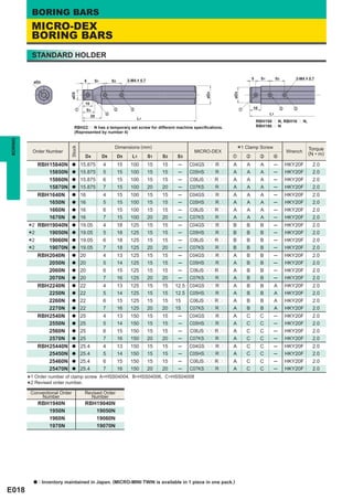
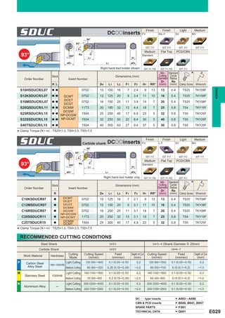
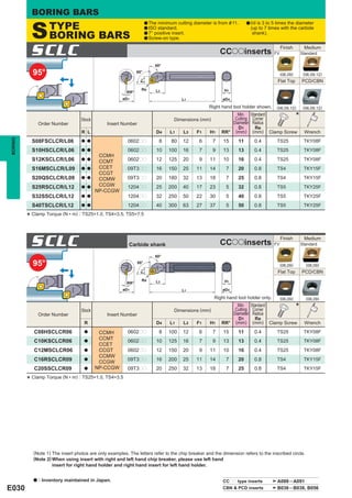
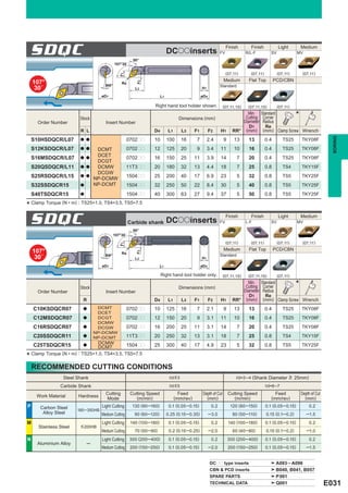
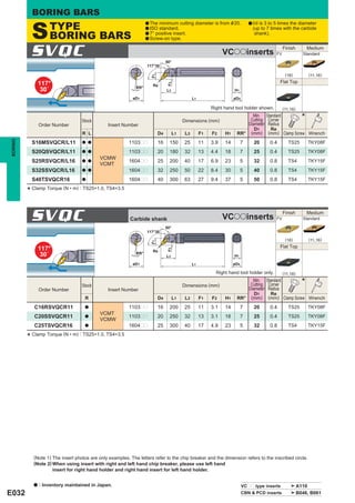
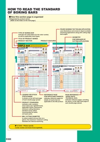
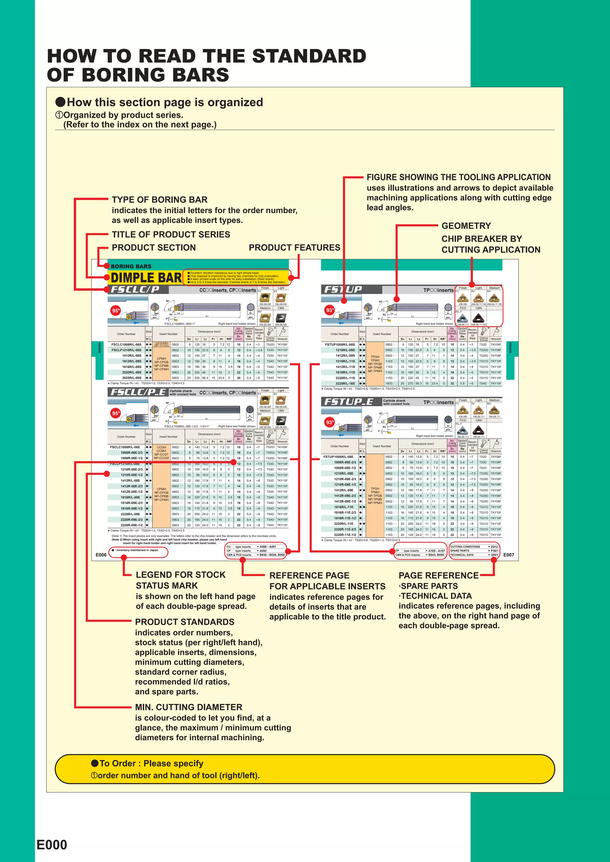
This document provides information on how to read the standard for boring bars.
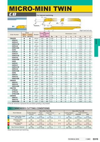
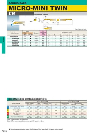
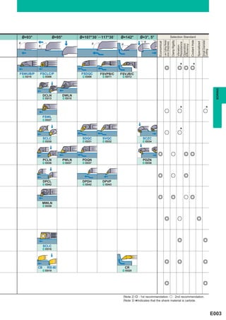
It is organized by product series, with each series listing specifications like insert type, geometry, stock dimensions, and recommended minimum diameters.
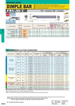
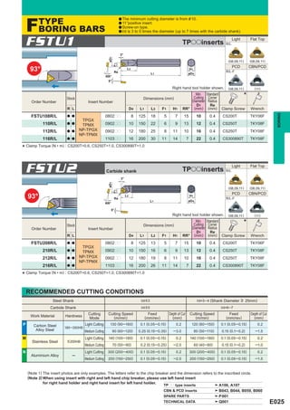
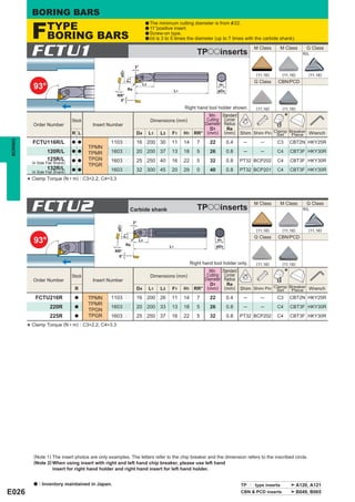
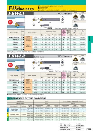
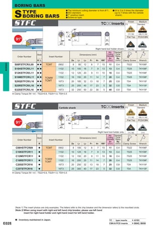
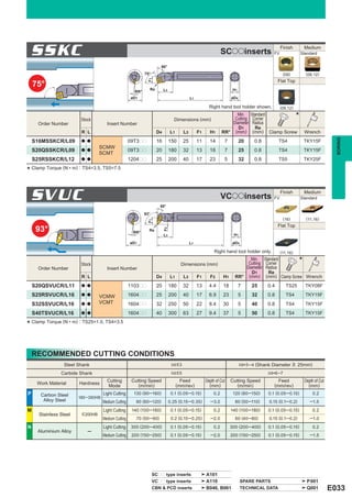
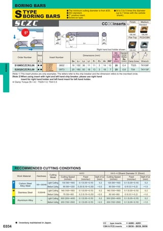
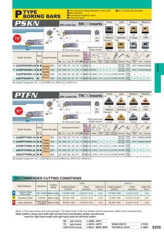
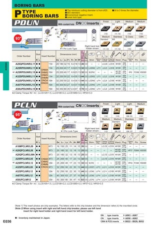
Pictures and diagrams are used to illustrate the available machining applications and cutting edge angles for each boring bar type.
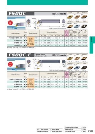
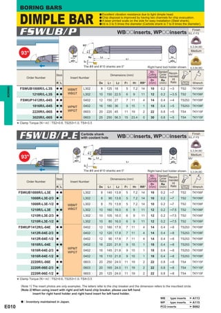
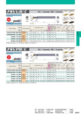
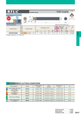
Specifications covered include insert number, dimensions, minimum standard diameters, cutting corner recommendations, clamp torques, and required wrenches.

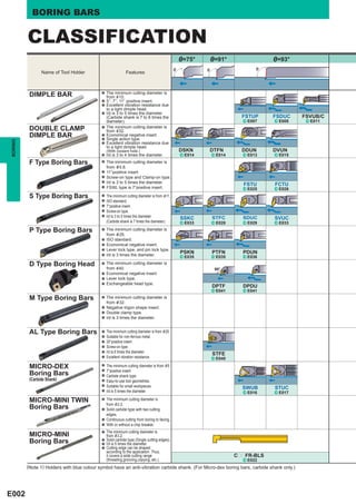
![BORING BARS
IDENTIFICATION
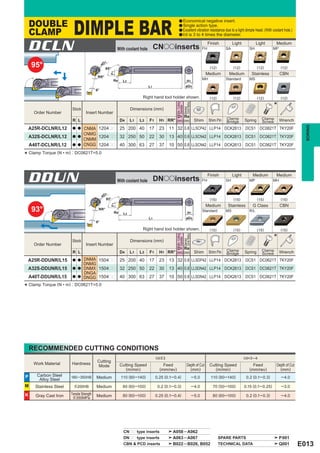
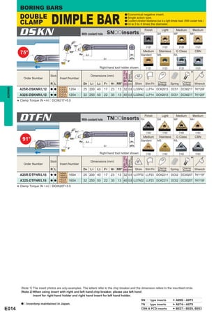
y DIMPLE BAR nMin.Cutting Diameter mShank Diameter
(mm) (mm)
10 10 22 22 08 8
cInsert Shape vCutting Angle 12 12 25 25 10 10
C RHOMBIC 80° U 93° 13 13 30 30 12 12
D RHOMBIC 55° L 95° bInsert Clearance 14 14 32 32 16 16
T TRIANGULAR 60° Q 107°30´ B 5° 16 16 34 34 20 20
zFunction xClamp Structure V RHOMBIC 35° P 117°30´ C 7° 18 18 40 40 25 25
F Fix type S Screw-on W TRIGON J 142° P 11° 20 20 32 32
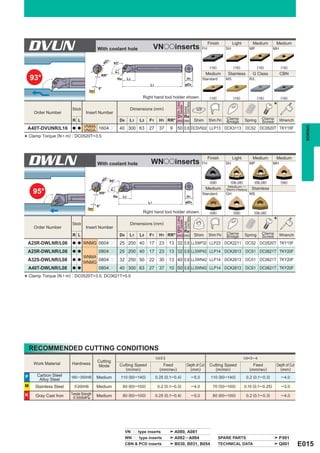
BORING
, . / u
11
F S C L C 10 08 R - 06 E - 2/3
z x c v b n m
,Hand of Tool .Cutting Edge Length (mm) /Shank Material u Tool Length (Carbide shank only) (mm)
11
Inscribed circle 4.76 5.56 6.35 7.94 9.525 E Shank Dia. 8 10 12 16 20
R Right Hand of insert Carbide Shank
L Left Hand RHOMBIC 80° – – 06 08 09 S Steel Shank No symbol 140 160 180 220 250
RHOMBIC 55° – – 07 – 11 2/3 90 105 120 145 165
TRIANGULAR 60° 08 09 11 – 16 1/2 70 80 90 110 125
RHOMBIC 35° 08 – 11 – 16
TRIGON L3 – 04 – 06
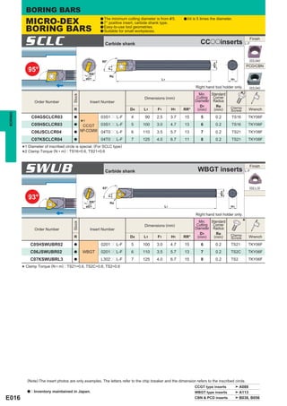
y ISO TYPE Boring tools
[For Aluminium Alloy, M-type, P-type and S-type]
S 16 M S C L C R 09
z x c v b n m , .
cTool Length
zShank Material (mm) vClamp Structure bInsert Shape mInsert Clearance ,Hand of Tool
A Steel Shank F 80 M Double Clamp C RHOMBIC 80° C 7°Positive R Right Hand
with Coolant Hole
H 100 P Lever Lock D RHOMBIC 55° E 20°Positive L Left Hand
C Carbide Shank
K 125 S Screw-on S SQUARE 90° N 0°
E Carbide Shank
with Coolant Hole M 150 T TRIANGULAR 60° P 11°Positive
S Steel Shank Q 180 V RHOMBIC 35°
R 200 W Trigon
S 250
T 300
xShank Diameter U 350
(mm) V 400 nCutting Angle .Cutting Edge Length (mm)
Inscribed circle
08 8 F 91° of insert 6.35 7.94 9.525 12.70 19.05
10 10 K 75° RHOMBIC 80° 06 08 09 12 19
12 12 L 95° RHOMBIC 55° 07 – 11 15 –
16 16 Q 107°30´ SQUARE 90° – – 09 12 19
20 20 U 93° TRIANGULAR 60° 11 – 16 22 –
25 25 RHOMBIC 35° 11 – 16 – –
32 32
40 40
E004](https://image.slidesharecdn.com/boringbars-130112060433-phpapp02/85/BORING-BARS-5-320.jpg)