Robotics is the field that studies machines called robots. Robots are programmable machines that can assist humans or mimic human actions. Originally built for monotonous assembly line tasks, robots now perform complex tasks like surgery. Robots range from fully human-controlled to fully autonomous. They are used widely in manufacturing, entertainment, and to improve quality of life. The main components of a robot include sensors, a control system, actuators, a power supply, and end effectors.


![Robotic Manipulator
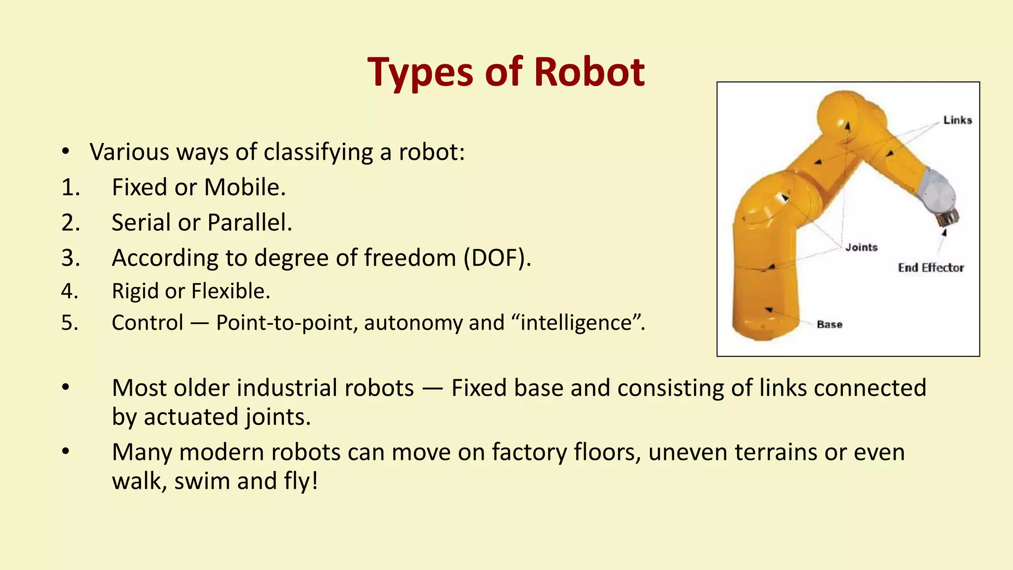
• Robotic manipulator is a mechanical structure formed by links and joints so
that they can control end- effector. It has a tool that allows manipulation
operation.
• The robotic manipulators are composed of:
Kinematic chain composed of Links and Joints.
The BASE: can be either fixed in the work environment or placed on a
mobile platform.
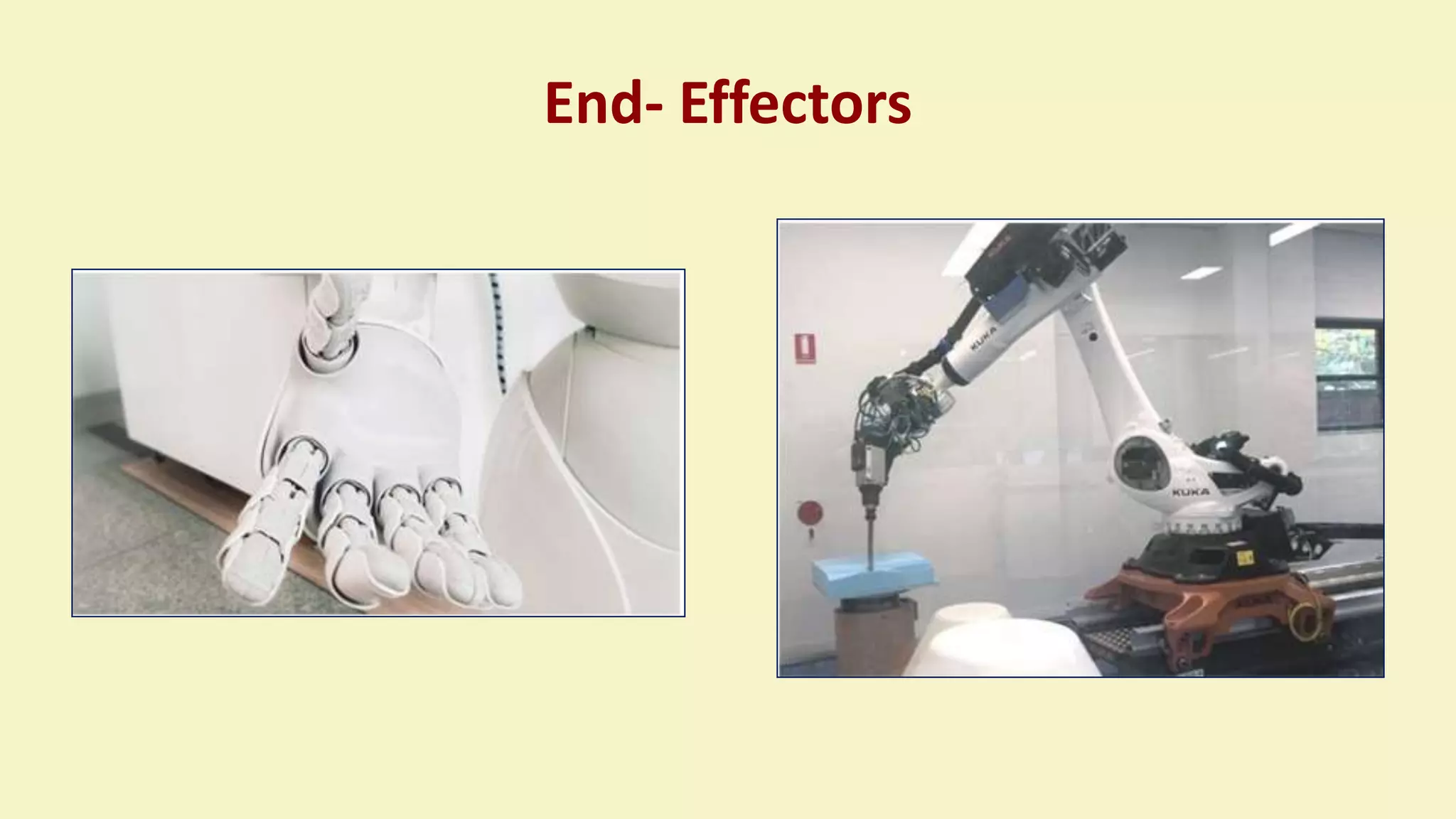
End-Effector: Tool is located at the end, used to execute the desired
operations [gripper or specic tool].](https://image.slidesharecdn.com/roboticsppt1-220926025628-c9f58294/75/Robotics-PPT-1-pptx-34-2048.jpg)


![ORIENTATION – PROPERTIES OF A
B[R]](https://image.slidesharecdn.com/roboticsppt1-220926025628-c9f58294/75/Robotics-PPT-1-pptx-59-2048.jpg)
![ORIENTATION – PROPERTIES OF A
B[R]](https://image.slidesharecdn.com/roboticsppt1-220926025628-c9f58294/75/Robotics-PPT-1-pptx-60-2048.jpg)