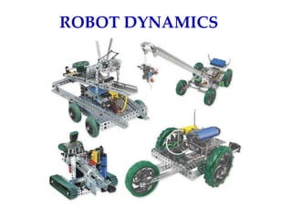
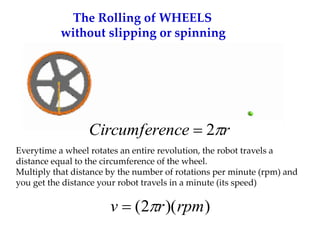
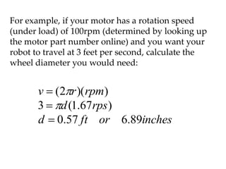
- Motors supply the force and torque needed for robots to move through wheels, arms, etc. The speed of a robot is determined by the wheel diameter and motor RPM.
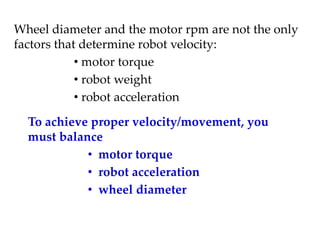
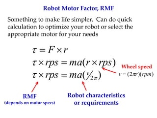
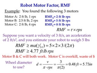
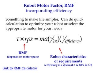
- Factors like motor torque, robot weight, acceleration, and wheel diameter must be balanced to achieve proper velocity. The robot motor factor (RMF) can be used to quickly calculate torque requirements.
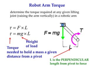
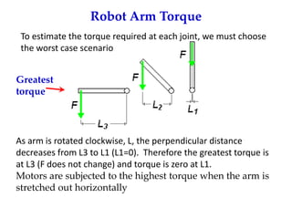
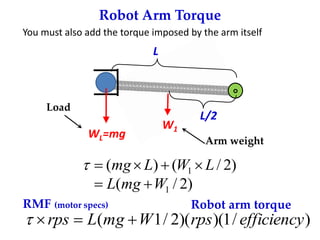
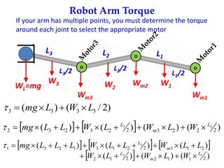
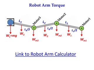
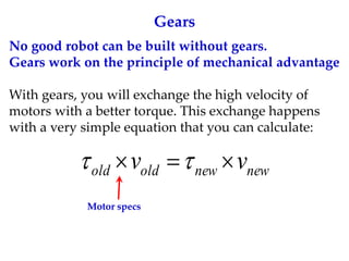
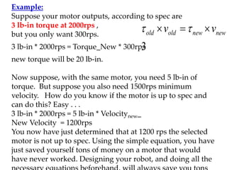
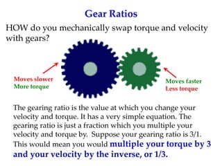
- For robot arms, the torque required at each joint must be calculated based on the load weight and distance from the pivot point to select the appropriate motor. Gears can be used to exchange torque and velocity.