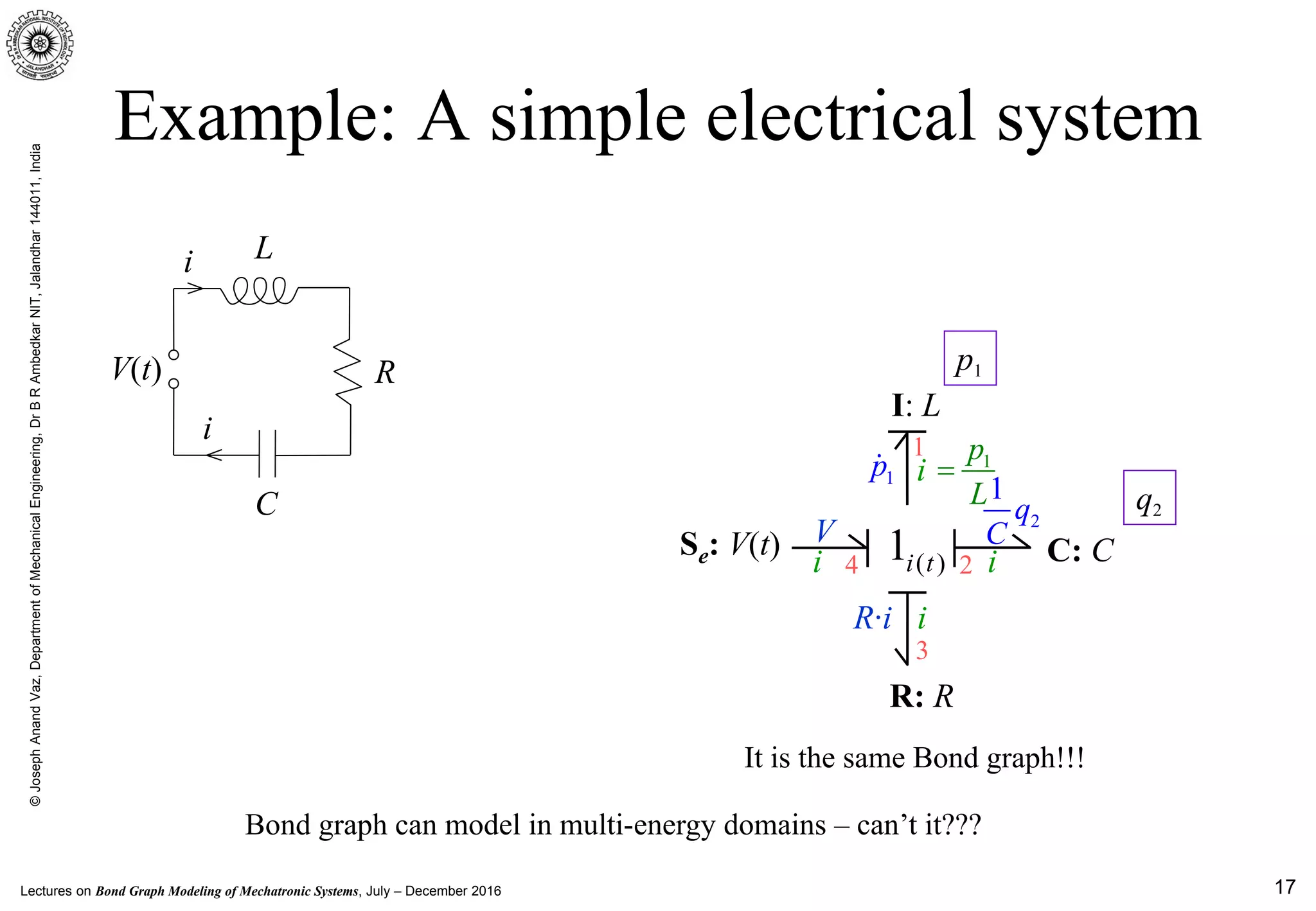
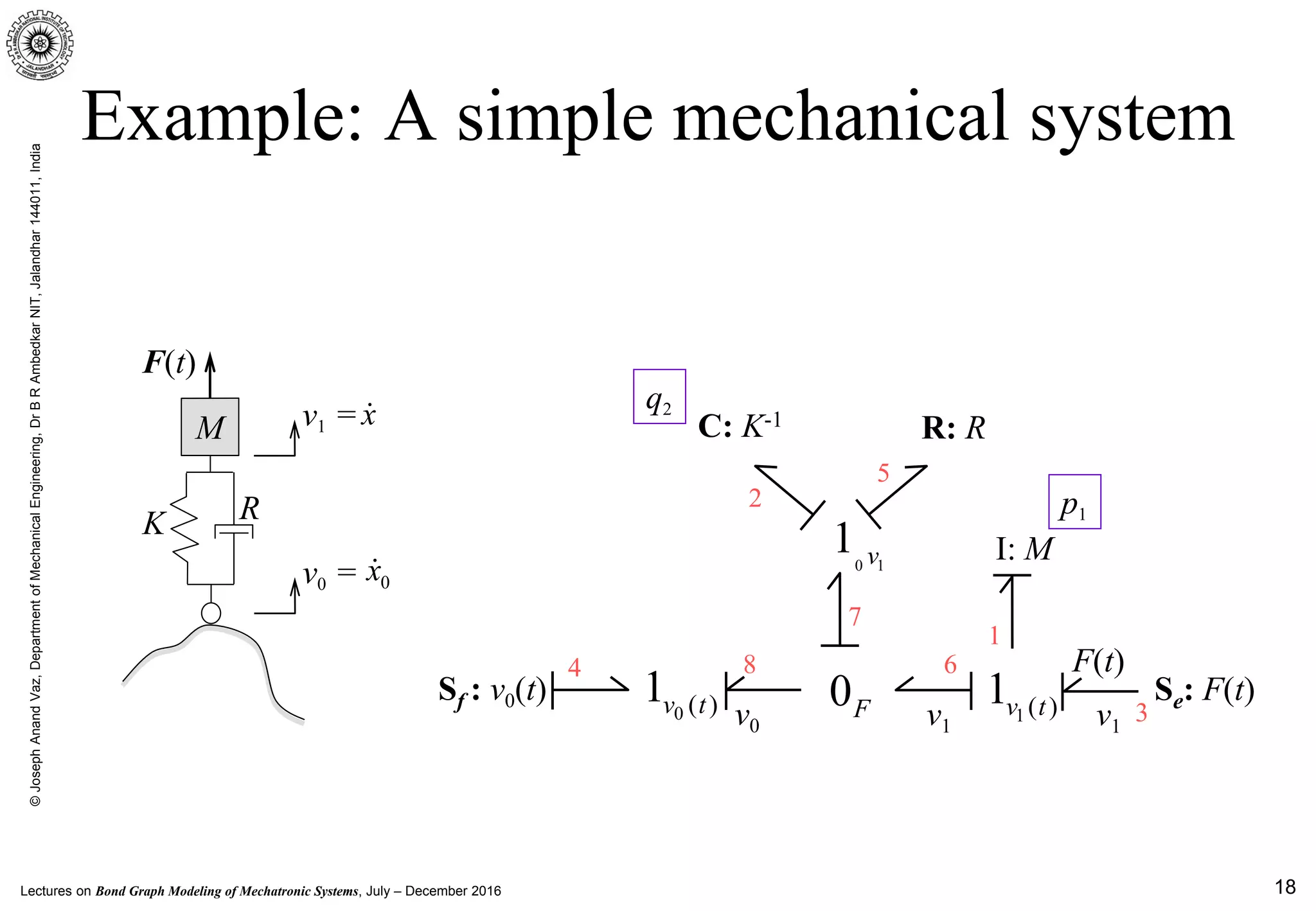
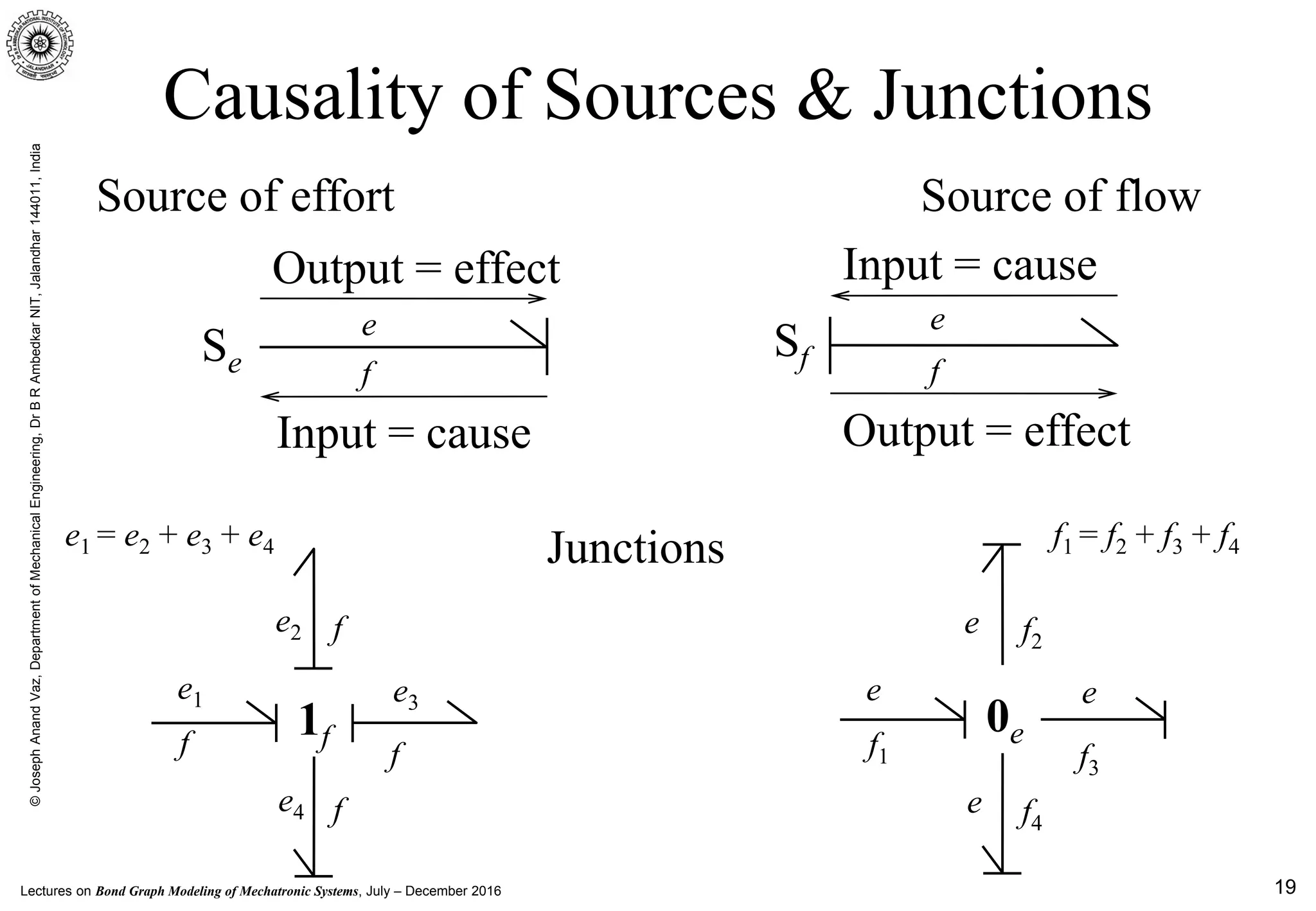
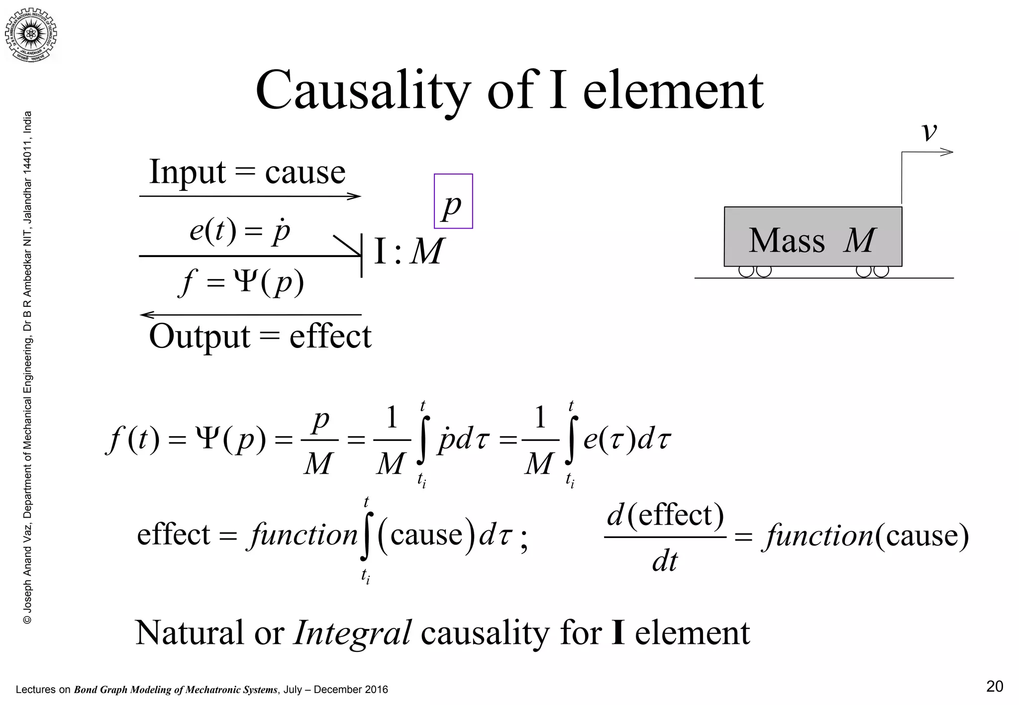
This document provides an introduction to modeling physical systems using bond graphs. It discusses physical systems and why modeling them is important. It then introduces bond graphs as a unified approach to modeling the dynamics of multi-domain physical systems using graphical elements. The key concepts of bond graphs like power bonds, effort/flow variables, elements, causality and junctions are explained. Examples of simple mechanical and electrical systems are modeled using bond graphs. The document emphasizes that bond graphs can provide insight into system behavior and that system equations can be algorithmically derived from the bond graph model.


![Lectures on Bond Graph Modeling of Mechatronic Systems, July – December 2016
©JosephAnandVaz,DepartmentofMechanicalEngineering,DrBRAmbedkarNIT,Jalandhar144011,India
51
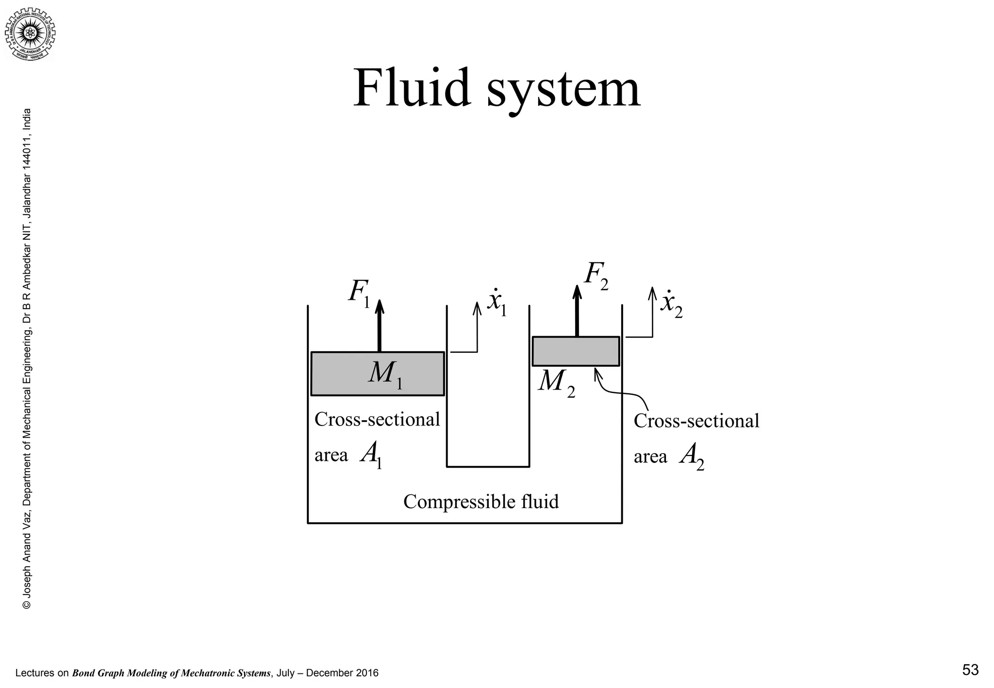
Fluid inertia
Q
v(t)
A
PA PB
Q
x∆
0
lim
t
x
v
t∆ →
∆
=
∆
0
lim
t
x
Q A v A
t∆ →
∆
= = ⋅
∆
( )0
lim A B
t
d x
A l P P A
dt t
ρ
∆ →
∆
⋅ ⋅ ⋅ = − ⋅ ∆
Q
1Q
PA PB
Q
l
A
ρ ⋅
I:
Pp Q
Applying Newton’s II Law,
[ ]P A B
d d l
p Q P P
dt dt A
ρ ⋅
= = −
l](https://image.slidesharecdn.com/lecturenotesonintroductiontophysicalsystemstheirmodelingandsimulation-abondgraphapproach02oct2016-171021091401/75/A-bond-graph-approach-simulation-and-modelling-Mechatronics-INDIA-51-2048.jpg)


![0066ch09.disaiaiufsagfuewgjdfduygdw78dtrblksh]0suglwt](https://cdn.slidesharecdn.com/ss_thumbnails/0066ch09-250117114605-371b0dbb-thumbnail.jpg?width=640&height=640&fit=bounds)