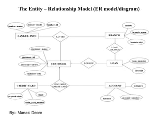
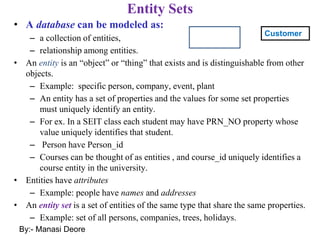
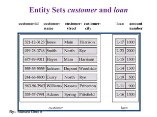
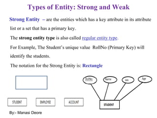
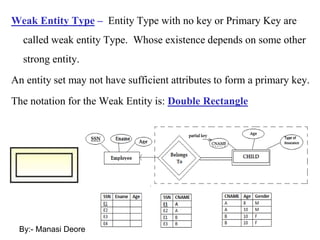
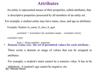
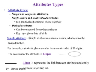
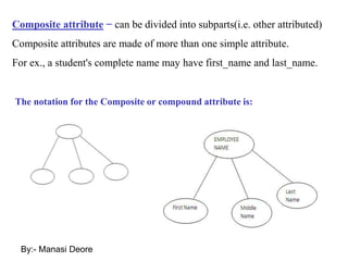
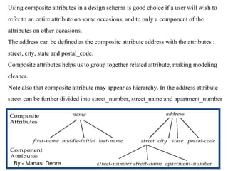
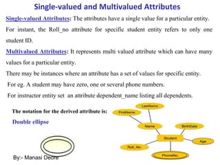
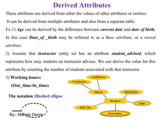
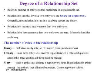
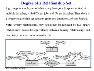
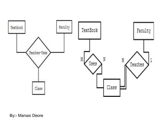
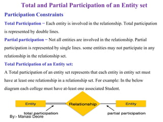
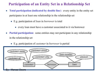
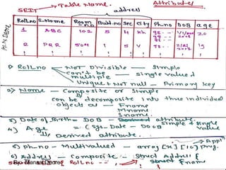
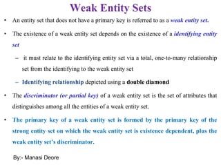
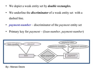
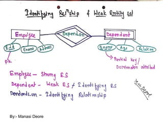
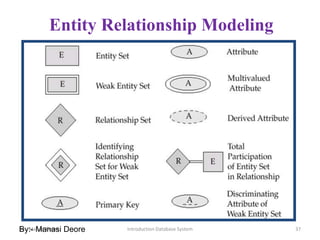
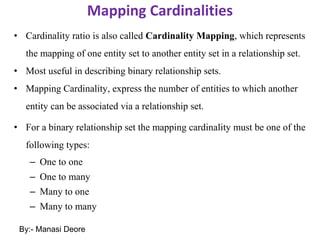
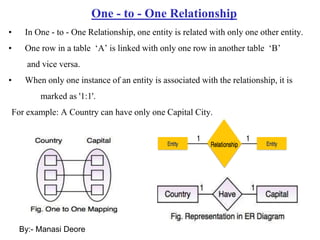
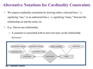
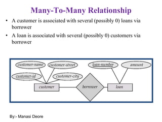
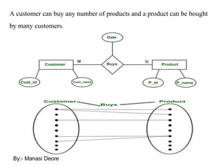
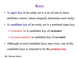
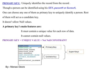
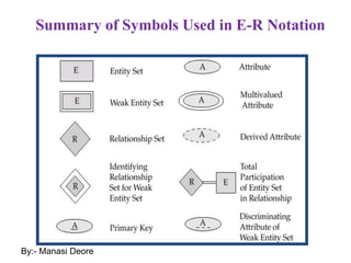
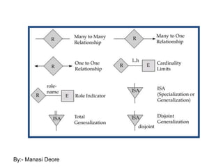
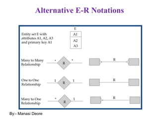
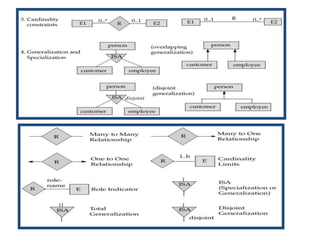
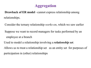
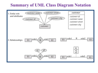
SlideShare a Scribd company logo
1
Chapter 2: Entity-Relationship Data Model
• Conceptual Modeling of a database
• The Entity-Relationship (ER) Model
• Entity Types, Entity Sets, Attributes, and Keys, Relationship
Types, Relationship Sets, Weak Entity Types
• Generalization, Specialization and Aggregation, Extended
Entity Relationship (EER) Model.
By:- Manasi Deore
2
Conceptual Modeling of a database
A data model helps to put the real world requirement into a design
Data Model is a collection of conceptual tools for describing data, data
relationships, data semantics, and consistency constraints.
It involves planning about tables, their columns, mapping between the
tables, how they are structured in the physical memory etc.
A collection of tools for describing:
Data
Data relationships
Data semantics
Data constraints
By:- Manasi Deore
By:- Manasi Deore
By:- Manasi Deore
The Entity – Relationship Model (ER model/diagram)
By:- Manasi Deore
The Entity – Relationship Model (ER model/diagram)
The ER data model was developed to facilitate database design by allowing
specification of an enterprise schema that represents the overall logical structure of
a database.
The E-R model is very useful in mapping the meaning and interactions of real
world enterprise onto a conceptual schema.
The E-R model employee three basic concepts: entity sets, relationship sets and
attributes.
The E-R model also has an associated diagrammatic representation: the E-R
diagram
An E-R diagram can express the overall logical structure of a database graphically.
This diagrams are simple and clear.
By:- Manasi Deore
Entity Sets
• A database can be modeled as:
– a collection of entities,
– relationship among entities.
• An entity is an “object” or “thing” that exists and is distinguishable from other
objects.
– Example: specific person, company, event, plant
– An entity has a set of properties and the values for some set properties
must uniquely identify an entity.
– For ex. In a SEIT class each student may have PRN_NO property whose
value uniquely identifies that student.
– Person have Person_id
– Courses can be thought of as entities , and course_id uniquely identifies a
course entity in the university.
• Entities have attributes
– Example: people have names and addresses
• An entity set is a set of entities of the same type that share the same properties.
– Example: set of all persons, companies, trees, holidays.
Customer
By:- Manasi Deore
Entity Sets customer and loan
customer-id customer- customer- customer- loan amount
name street city number
By:- Manasi Deore
Types of Entity: Strong and Weak
Strong Entity – are the entities which has a key attribute in its attribute
list or a set that has a primary key.
The strong entity type is also called regular entity type.
For Example, The Student’s unique value RollNo (Primary Key) will
identify the students.
The notation for the Strong Entity is: Rectangle
By:- Manasi Deore
Weak Entity Type – Entity Type with no key or Primary Key are
called weak entity Type. Whose existence depends on some other
strong entity.
An entity set may not have sufficient attributes to form a primary key.
The notation for the Weak Entity is: Double Rectangle
By:- Manasi Deore
Attributes
An entity is represented means of their properties, called attributes, that
is descriptive properties possessed by all members of an entity set.
For example, a student entity may have name, class, and age as attributes.
• Domain (value set)– the set of permitted values for each attribute .
There exists a domain or range of values that can be assigned to
attributes.
For example, a student's name cannot be a numeric value. It has to be
alphabetic. A student's age cannot be negative, etc.
Example: Student=(s_name, S_class, S_age)
customer = (customer-id, customer-name, customer-street,
customer-city)
loan = (loan-number, amount)
By:- Manasi Deore
Attributes Types
• Attribute types:
– Simple and composite attributes.
– Single-valued and multi-valued attributes
• E.g. multivalued attribute: phone-numbers
– Derived attributes
• Can be computed from other attributes
• E.g. age, given date of birth
Simple attribute − Simple attributes are atomic values, which cannot be
divided further.
For example, a student's phone number is an atomic value of 10 digits.
The notation for the attribute is: Ellipse
Line: It represents the link between attribute and entity
set to relationship set.
By:- Manasi Deore
The notation for the Composite or compound attribute is:
Composite attribute − can be divided into subparts(i.e. other attributed)
Composite attributes are made of more than one simple attribute.
For ex., a student's complete name may have first_name and last_name.
By:- Manasi Deore
Using composite attributes in a design schema is good choice if a user will wish to
refer to an entire attribute on some occasions, and to only a component of the
attributes on other occasions.
The address can be defined as the composite attribute address with the attributes :
street, city, state and postal_code.
Composite attributes helps us to group together related attribute, making modeling
cleaner.
Note also that composite attribute may appear as hierarchy. In the address attribute
street can be further divided into street_number, street_name and apartment_number
By:- Manasi Deore
Single-valued and Multivalued Attributes
Single-valued Attributes: The attributes have a single value for a particular entity.
For instant, the Roll_no attribute for specific student entity refers to only one
student ID.
Multivalued Attributes: It represents multi valued attribute which can have many
values for a particular entity.
There may be instances where an attribute has a set of values for specific entity.
For eg. A student may have zero, one or several phone numbers.
For instructor entity set an attribute dependent_name listing all dependents.
The notation for the derived attribute is:
Double ellipse
By:- Manasi Deore
Derived Attributes
These attributes are derived from other the values of other attributes or entities.
It can be derived from multiple attributes and also from a separate table.
Ex.1) Age can be derived by the difference between current date and date of birth.
In this case Date_of _birth may be referred to as a Base attribute, or a stored
attribute.
2) Assume that instructor entity set has an attribute student_advised, which
represents how may students an instructor advises. We can derive the value for this
attribute by counting the number of students associated with that instructor
3) Working hours:
(Out_time-In_time)
The notation :Dashed ellipse
By:- Manasi Deore
Relationship Sets
A relationship is an association among several entities.
Relationships are represented by diamond-shaped box.
Name of the relationship is written inside the diamond-box.
All the entities (rectangles/Double rectangles) participating in a
relationship, are connected to it by a line.
Belongs to
By:- Manasi Deore
Relationship Set: set of similar relationships
Student (entity type) is related to Department (entity type)
by MajorsIn (relationship set or entity role).
Relationship sets can have descriptive attributes like entity sets.
The Function that an entity plays in a relationship is called that entity’s role
By:- Manasi Deore
Relationship Set borrower
By:- Manasi Deore
Relationship Sets (Cont.)
• An attribute can also be property of a relationship set.
• For instance, the depositor relationship set between entity sets customer
and account may have the attribute access-date
By:- Manasi Deore
Degree of a Relationship Set
• Refers to number of entity sets that participate in a relationship set.
• Relationship sets that involve two entity sets are binary (or degree two).
Generally, most relationship sets in a database system are binary.
• Relationship sets may involve more than two entity sets.
• Relationships between more than two entity sets are rare. Most relationships
are binary.
The number of roles in the relationship
Binary – links two entity sets; set of ordered pairs (most common)
Ternary – links three entity sets; ordered triples (rare). If a relationship exists
among the three entities, all three must be present
N-ary – links n entity sets; ordered n-tuples (very rare). If a relationship exists
among the entities, then all must be present. Cannot represent subsets.
By:- Manasi Deore
Degree of a Relationship Set
E.g. Suppose employees of a bank may have jobs (responsibilities) at
multiple branches, with different jobs at different branches. Then there is
a ternary relationship set between entity sets employee, job and branch.
Note: ternary relationships may sometimes be replaced by two binary
relationships. Semantic equivalence between ternary relationships and
two binary ones are not necessarily true.
By:- Manasi Deore
By:- Manasi Deore
Total and Partial Participation of an Entity set
Participation Constraints
Total Participation − Each entity is involved in the relationship. Total participation
is represented by double lines.
Partial participation − Not all entities are involved in the relationship. Partial
participation is represented by single lines. some entities may not participate in any
relationship in the relationship set.
Total Participation of an Entity set:
A Total participation of an entity set represents that each entity in entity set must
have at least one relationship in a relationship set. For example: In the below
diagram each college must have at-least one associated Student.
By:- Manasi Deore
Participation of an Entity Set in a Relationship Set
● Total participation (indicated by double line): every entity in the entity set
participates in at least one relationship in the relationship set
● E.g. participation of loan in borrower is total
● every loan must have a customer associated to it via borrower
● Partial participation: some entities may not participate in any relationship
in the relationship set
● E.g. participation of customer in borrower is partial
By:- Manasi Deore
By:- Manasi Deore
Recursive Relationship(entities can be self-linked)
If the same entity participates more than once in a relationship it is
known as a recursive relationship. In the example an employee can
be a supervisor and be supervised, so there is a recursive
relationship.
By:- Manasi Deore
• Entity sets of a relationship need not be distinct
• The labels “manager” and “worker” are called roles; they specify
how employee entities interact via the works-for relationship set.
• Roles are indicated in E-R diagrams by labeling the lines that
connect diamonds to rectangles.
• Role labels are optional, and are used to clarify semantics of the
relationship
By:- Manasi Deore
By:- Manasi Deore
Weak Entity Sets
• An entity set that does not have a primary key is referred to as a weak entity set.
• The existence of a weak entity set depends on the existence of a identifying entity
set
– it must relate to the identifying entity set via a total, one-to-many relationship
set from the identifying to the weak entity set
– Identifying relationship depicted using a double diamond
• The discriminator (or partial key) of a weak entity set is the set of attributes that
distinguishes among all the entities of a weak entity set.
• The primary key of a weak entity set is formed by the primary key of the
strong entity set on which the weak entity set is existence dependent, plus the
weak entity set’s discriminator.
By:- Manasi Deore
• We depict a weak entity set by double rectangles.
• We underline the discriminator of a weak entity set with a
dashed line.
• payment-number – discriminator of the payment entity set
• Primary key for payment – (loan-number, payment-number)
By:- Manasi Deore
By:- Manasi Deore
By:- Manasi Deore
By:- Manasi Deore
• Note: the primary key of the strong entity set is not explicitly
stored with the weak entity set, since it is implicit in the
identifying relationship.
• If loan-number were explicitly stored, payment could be made a
strong entity, but then the relationship between payment and loan
would be duplicated by an implicit relationship defined by the
attribute loan-number common to payment and loan
By:- Manasi Deore
• In a university, a course is a strong entity and a course-offering
can be modeled as a weak entity
• The discriminator of course-offering would be semester
(including year) and section-number (if there is more than one
section)
• If we model course-offering as a strong entity we would model
course-number as an attribute.
Then the relationship with course would be implicit in the course-
number attribute
By:- Manasi Deore
Introduction Database System 37
Entity Relationship Modeling
By:- Manasi Deore
By:- Manasi Deore
Mapping Cardinalities
• Cardinality ratio is also called Cardinality Mapping, which represents
the mapping of one entity set to another entity set in a relationship set.
• Most useful in describing binary relationship sets.
• Mapping Cardinality, express the number of entities to which another
entity can be associated via a relationship set.
• For a binary relationship set the mapping cardinality must be one of the
following types:
– One to one
– One to many
– Many to one
– Many to many
By:- Manasi Deore
One - to - One Relationship
• In One - to - One Relationship, one entity is related with only one other entity.
• One row in a table ‘A’ is linked with only one row in another table ‘B’
and vice versa.
• When only one instance of an entity is associated with the relationship, it is
marked as '1:1'.
For example: A Country can have only one Capital City.
By:- Manasi Deore
Alternative Notations for Cardinality Constraints
• We express cardinality constraints by drawing either a directed line (🡪),
signifying “one,” or an undirected line (—), signifying “many,” between the
relationship set and the entity set.
• E.g.: One-to-one relationship:
– A customer is associated with at most one loan via the relationship
borrower
– A loan is associated with at most one customer via borrower
By:- Manasi Deore
Each customer has exactly one driving license and every driving
license is associated with exactly one customer.
By:- Manasi Deore
One - to - Many Relationship
•When more than one instance of an entity is associated with a relationship i.e. one
entity is related to many other entities.
•It is marked as '1:N'.
•One row in a table A is linked to many rows in a table B, but one row in a table B
is linked to only one row in table A.
For example: One Department has many Employees.
By:- Manasi Deore
One-To-Many Relationship
• In the one-to-many relationship a loan is associated with at most
one customer via borrower, a customer is associated with several
(including 0) loans via borrower
By:- Manasi Deore
There are some employees who manage more than one team
while there is only one manager to manage a team
By:- Manasi Deore
Many - to - One Relationship
•When more than one instance of entity is associated with the relationship i.e. In
Many - to - One Relationship, many entities can be related with only one other
entity.
•It is marked as ‘N:1'.
•Multiple rows in Employee table(table A) is related with only one row in
Department table (table B).
•For example: No. of Employee works for Department and employee belongs to
only one department.
By:- Manasi Deore
Many-To-One Relationships
• In a many-to-one relationship a loan is associated with several
(including 0) customers via borrower, a customer is associated with at
most one loan via borrower
By:- Manasi Deore
Any number of credit cards can belong to a customer and there might be
some customers who do not have any credit card, but every credit card in a
system has to be associated with an employee(i.e. total participation).
While a single credit card can not belong to multiple customers.
By:- Manasi Deore
Many - to – Many Relationship
•More than one instance of an entity on the left and more than one instance of an
entity on the right can be associated with the relationship.
•It is marked as ‘N:N ‘ or ‘M:N’.
•In Many - to - Many Relationship, many entities are related with the multiple
other entities.
•For example: Various Books in a Library are issued by many Students.
By:- Manasi Deore
Many-To-Many Relationship
• A customer is associated with several (possibly 0) loans via
borrower
• A loan is associated with several (possibly 0) customers via
borrower
By:- Manasi Deore
A customer can buy any number of products and a product can be bought
by many customers.
By:- Manasi Deore
Keys
• A super key of an entity set is a set of one or more
attributes whose values uniquely determine each entity.
• A candidate key of an entity set is a minimal super key
– Customer-id is candidate key of customer
– account-number is candidate key of account
• Although several candidate keys may exist, one of the
candidate keys is selected to be the primary key.
By:- Manasi Deore
PRIMARY KEY: Uniquely identifies the record from the record .
•Though a person can be identified using his SSN, passort# or license#,
•One can choose any one of them as primary key to uniquely identify a person. Rest
of them will act as a candidate key.
•It doesn’t allow Null values.
A primary key’s main features are:
It must contain a unique value for each row of data.
It cannot contain null values.
PRIMARY KEY = UNIQUE VALUE + Not Null CONSTRAINT
By:- Manasi Deore
• Unique key: Allows Null value. But only one Null value.
• Foreign key: In simpler words, the foreign key is defined in a second table,
but it refers to the primary key or a unique key in the first table.
A Foreign key is a field (or collection of fields) in one table that refers to the
Primary key in another table..
Foreign key helps to establish the mapping between two or more entities.
By:- Manasi Deore
Keys for Relationship Sets
• The combination of primary keys of the participating entity sets forms a super
key of a relationship set.
– (customer-id, account-number) is the super key of depositor
– NOTE: this means a pair of entity sets can have at most one relationship in
a particular relationship set.
• E.g. if we wish to track all access-dates to each account by each
customer, we cannot assume a relationship for each access. We can use
a multivalued attribute though
• Must consider the mapping cardinality of the relationship set when deciding the
what are the candidate keys
• Need to consider semantics of relationship set in selecting the primary key in
case of more than one candidate key
By:- Manasi Deore
By:- Manasi Deore
How to Draw ER Diagrams
Below points show how to go about creating an ER diagram.
Identify all the entities in the system. An entity should appear only
once in a particular diagram. Create rectangles for all entities and
name them properly.
Identify relationships between entities. Connect them using a line
and add a diamond in the middle describing the relationship.
Add attributes for entities. Give meaningful attribute names so they
can be understood easily.
By:- Manasi Deore
E-R Diagram With Composite, Multivalued, and Derived
Attributes
By:- Manasi Deore
Ag
Simple ER diagram for University Database
By:- Manasi Deore
Binary Vs. Non-Binary Relationships
• Some relationships that appear to be non-binary may be better
represented using binary relationships
– E.g. A ternary relationship parents, relating a child to
his/her father and mother, is best replaced by two binary
relationships, father and mother
• Using two binary relationships allows partial
information (e.g. only mother being know)
– But there are some relationships that are naturally non-
binary
• E.g. works-on
By:- Manasi Deore
E-R Diagram for a Banking Enterprise
By:- Manasi Deore
Summary of Symbols Used in E-R Notation
By:- Manasi Deore
By:- Manasi Deore
Alternative E-R Notations
By:- Manasi Deore
By:- Manasi Deore
Database Languages
Language for accessing and manipulating the data organized by the appropriate data model.
Two classes of languages
Procedural – user specifies what data is required and how to get those data
Nonprocedural – user specifies what data is required without specifying how to get
those data
Types of DBMS languages
Data Definition Language (DDL)
Data Manipulation Language (DML)
Data Control Language (DCL)
Transaction Control (TCL)
Data Definition Language (DDL) : Statements are used to define the database structure or
schema.
Some examples:
CREATE - to create objects in the database
ALTER - alters the structure of the database
DROP - delete objects from the database
TRUNCATE - remove all records from a table, including all spaces allocated for the records
are removed
COMMENT - add comments to the data dictionary
RENAME - rename an object
By:- Manasi Deore
Manipulation Language (DML) : Statements are used for managing data within schema
objects.
Some examples:
SELECT - Retrieve data from the a database
INSERT - Insert data into a table
UPDATE - Updates existing data within a table
DELETE - deletes all records from a table
Data Control Language (DCL)
Some examples:
GRANT - gives user's access privileges to database
REVOKE - withdraw access privileges given with the GRANT command
Transaction Control (TCL) : Statements are used to manage the changes made by DML
statements. It allows statements to be grouped together into logical transactions.
Some examples:
COMMIT - save work done
SAVEPOINT - identify a point in a transaction to which you can later roll back
ROLLBACK - restore database to original since the last COMMIT
SET TRANSACTION - Change transaction options like isolation level and what rollback
segment to use
The Enhanced Entity Relationship (EER) :
Model Enhanced ER (EER) model
• Created to design more accurate database schemas
• Reflect the data properties and constraints more precisely
• More complex requirements than traditional applications
The EER model includes all the concepts of the original E-R model
together with the following concepts:
1.Specialization
2.Generalization
•Aggregation
•Inheritance
The Enhanced Entity Relationship (EER)
By:- Manasi Deore
Introduction Database
System
Sub Class and Super Class
•Sub class and Super class relationship leads the concept of Inheritance.
•The relationship between sub class and super class is denoted with symbol.
1. Super Class
Super class is an entity type that has a relationship with one or more subtypes.
For example: Shape super class is having sub groups as Square, Circle, Triangle.
2. Sub Class
•Sub class is a group of entities with unique attributes.
•Sub class inherits properties and attributes from its super class.
For example: Square, Circle, Triangle
are the sub class of Shape super class.
Specialization
Specialization is the process of defining a set of subclasses of an entity type
Specialization is a process that defines a group entities which is divided into
sub groups based on their characteristic.
•Top-down design process: in which one higher entity can be broken down
into two lower level entity, that are distinctive from other entities in the set.
•These sub groupings become lower-level entity sets that have attributes or
participate in relationships that do not apply to the higher-level entity set.
• It maximizes the difference between the members of an entity by identifying
the unique characteristic or attributes of each member.
•It defines one or more sub class for the super class and also forms the
superclass/subclass relationship.
Specialization
•Depicted by a triangle component labeled ISA (E.g. customer “is a” person).
•Attribute inheritance – a lower-level entity set inherits all the attributes and
relationship participation of the higher-level entity set to which it is linked.
ISA
Generalization
Generalization is the process of generalizing the entities which contain
the properties of all the generalized entities.
Original entity types are special subclasses
Process of defining a generalized entity type from the given entity types
A bottom-up design process – combine a number of entity sets that share
the same features into a higher-level entity set (i.e.in which two lower
level entities combine to form a higher level entity).
Specialization and generalization are simple inversions of each other; they
are represented in an E-R diagram in the same way.
It defines a general entity type from a set of specialized entity type.
Generalization
It minimizes the difference between the entities by identifying the
common features.
The terms specialization and generalization are used interchangeably.
Implements Attribute inheritance.
By:- Manasi Deore
By:- Manasi Deore
Let us start with the bottom. Consider three categories of Employee
FULLTIME, PARTTIME, ADHOC which have common attributes and
specialized attributes. For instance, in the above diagram, FULLTIME
employee has a special attribute designation, PARTTIME employee two
special attributes namely number of days and task, ADHOC has hours as
its special attribute. All these three sub-entities can be generalized as a
super-entity called EMPLOYEE because ultimately all three types –
fulltime, partime and adhoc are types of employees. And thereby the
common attribute will be present for EMPLOYEE – super-entity and not
the child entity since it makes more sense for a parent entity to have a
common attribute and child attributes have their own special attributes
which are not present in other entities.
Specialization Example
Specialization and Generalization
• Can have multiple specializations of an entity set based on different
features.
• E.g. permanent-employee vs. temporary-employee, in addition to
officer vs. secretary vs. teller
• Each particular employee would be
– a member of one of permanent-employee or temporary-employee,
– and also a member of one of officer, secretary, or teller
• The ISA relationship also referred to as superclass - subclass
relationship
Design Constraints on a Specialization/Generalization
Constraint on which entities can be members of a given lower-level
entity set.
– condition-defined: If all subclasses have their membership (explicit)
condition on some attribute of superclass.
Ex. Over 65 years are members of senior-citizen entity set; senior-
citizen ISA person.
– user-defined : when we don't have predefined condition for
determining membership to a subclass.
– So we need condition determined by database user,
Design Constraints on a Specialization/Generalization
• Constraint on whether or not entities may belong to more than one
lower-level entity set within a single generalization.
– Disjoint
• an entity can belong to only one lower-level entity set
• Noted in E-R diagram by writing disjoint next to the ISA triangle
• Specifies that the subclasses of the specialization must be disjoint
– Overlapping
• an entity can belong to more than one lower-level entity set
By:- Manasi Deore
By:- Manasi Deore
Design Constraints on a Specialization/Generalization
Completeness constraint -- specifies whether or not an entity in
the higher-level entity set must belong to at least one of the
lower-level entity sets within a generalization.
– total : According to this constraint, each higher-level entity
must belong to a lower-level entity .
– partial: According to this constraint, higher-level entity need
not belong to one of the lower-level entity sets
Aggregation
Drawback of ER model –cannot express relationship among
relationships.
Consider the ternary relationship works-on, which we saw earlier
Suppose we want to record managers for tasks performed by an
employee at a branch
Used to model a relationship involving a relationship set.
Allows us to treat a relationship set as an entity set for purposes of
participation in (other) relationships
Used to model a relationship involving a relationship set.
Allows us to treat a relationship set as an entity set for purposes
of participation in (other) relationships
• Relationship sets works-on and manages represent overlapping information
– Every manages relationship corresponds to a works-on relationship
– However, some works-on relationships may not correspond to any manages
relationships
• So we can’t discard the works-on relationship
• Eliminate this redundancy via aggregation
– Treat relationship as an abstract entity
– Allows relationships between relationships
– Abstraction of relationship into new entity
• Without introducing redundancy, the following diagram represents:
– An employee works on a particular job at a particular branch
– An employee, branch, job combination may have an associated manager
E-R Diagram for a Banking Enterprise
Summary of Symbols
E-R Design Decisions
• The use of an attribute or entity set to represent an object.
• Whether a real-world concept is best expressed by an entity set or a
relationship set.
• The use of a ternary relationship versus a pair of binary
relationships.
• The use of a strong or weak entity set.
• The use of specialization/generalization – contributes to modularity
in the design.
• The use of aggregation – can treat the aggregate entity set as a single
unit without concern for the details of its internal structure.
Alternative E-R Notations
Summary of UML Class Diagram Notation

More Related Content

Similar to The Entity-Relationship Model(ER Diagram).pptx

Revision ch 3
Revision ch 3Revision ch 3
Revision ch 3
Rupali Rana
 
Fundamentals of database system - Data Modeling Using the Entity-Relationshi...
Fundamentals of database system  - Data Modeling Using the Entity-Relationshi...Fundamentals of database system  - Data Modeling Using the Entity-Relationshi...
Fundamentals of database system - Data Modeling Using the Entity-Relationshi...
Mustafa Kamel Mohammadi
 
E_R-Diagram (2).pptx
E_R-Diagram (2).pptxE_R-Diagram (2).pptx
E_R-Diagram (2).pptx
sandeep54552
 
Entityrelationshipmodel
EntityrelationshipmodelEntityrelationshipmodel
Entityrelationshipmodel
Enes Bolfidan
 
Chapter3
Chapter3Chapter3
Chapter3
Jafar Nesargi
 
Chapter3
Chapter3Chapter3
Chapter3
Jafar Nesargi
 
Er diagrams
Er diagramsEr diagrams
Er diagrams
VisnuDharsini
 
Day 1 SQL.pptx
Day 1 SQL.pptxDay 1 SQL.pptx
Day 1 SQL.pptx
raghuKatagall1
 
SQL.pptx
SQL.pptxSQL.pptx
SQL.pptx
raghuKatagall1
 
Basic concepts of Data and Databases
Basic concepts of Data and Databases Basic concepts of Data and Databases
Basic concepts of Data and Databases
Tharindu Weerasinghe
 
ER Diagram_Kameshwari.docx
ER Diagram_Kameshwari.docxER Diagram_Kameshwari.docx
ER Diagram_Kameshwari.docx
KameshwariPurusothma
 
3. Chapter Three.pdf
3. Chapter Three.pdf3. Chapter Three.pdf
3. Chapter Three.pdf
fikadumola
 
Data modeling using the entity relationship model
Data modeling using the entity relationship modelData modeling using the entity relationship model
Data modeling using the entity relationship model
Jafar Nesargi
 
ER-Model-ER Diagram
ER-Model-ER DiagramER-Model-ER Diagram
ER-Model-ER Diagram
Saranya Natarajan
 
DBMS Class 3
DBMS Class 3DBMS Class 3
Data modeling
Data modelingData modeling
Data modeling
Tala Alnaber
 
Entity Relationship Model
Entity Relationship ModelEntity Relationship Model
Entity Relationship Model
Slideshare
 
Unit02 dbms
Unit02 dbmsUnit02 dbms
Unit02 dbms
arnold 7490
 
Jobs manager vs supervisor.pptx
Jobs manager vs supervisor.pptxJobs manager vs supervisor.pptx
Jobs manager vs supervisor.pptx
prosofts1
 
Data Models.pptx
Data Models.pptxData Models.pptx
Data Models.pptx
CheriviralaNikhil
 

Similar to The Entity-Relationship Model(ER Diagram).pptx (20)

Revision ch 3
Revision ch 3Revision ch 3
Revision ch 3
 
Fundamentals of database system - Data Modeling Using the Entity-Relationshi...
Fundamentals of database system  - Data Modeling Using the Entity-Relationshi...Fundamentals of database system  - Data Modeling Using the Entity-Relationshi...
Fundamentals of database system - Data Modeling Using the Entity-Relationshi...
 
E_R-Diagram (2).pptx
E_R-Diagram (2).pptxE_R-Diagram (2).pptx
E_R-Diagram (2).pptx
 
Entityrelationshipmodel
EntityrelationshipmodelEntityrelationshipmodel
Entityrelationshipmodel
 
Chapter3
Chapter3Chapter3
Chapter3
 
Chapter3
Chapter3Chapter3
Chapter3
 
Er diagrams
Er diagramsEr diagrams
Er diagrams
 
Day 1 SQL.pptx
Day 1 SQL.pptxDay 1 SQL.pptx
Day 1 SQL.pptx
 
SQL.pptx
SQL.pptxSQL.pptx
SQL.pptx
 
Basic concepts of Data and Databases
Basic concepts of Data and Databases Basic concepts of Data and Databases
Basic concepts of Data and Databases
 
ER Diagram_Kameshwari.docx
ER Diagram_Kameshwari.docxER Diagram_Kameshwari.docx
ER Diagram_Kameshwari.docx
 
3. Chapter Three.pdf
3. Chapter Three.pdf3. Chapter Three.pdf
3. Chapter Three.pdf
 
Data modeling using the entity relationship model
Data modeling using the entity relationship modelData modeling using the entity relationship model
Data modeling using the entity relationship model
 
ER-Model-ER Diagram
ER-Model-ER DiagramER-Model-ER Diagram
ER-Model-ER Diagram
 
DBMS Class 3
DBMS Class 3DBMS Class 3
DBMS Class 3
 
Data modeling
Data modelingData modeling
Data modeling
 
Entity Relationship Model
Entity Relationship ModelEntity Relationship Model
Entity Relationship Model
 
Unit02 dbms
Unit02 dbmsUnit02 dbms
Unit02 dbms
 
Jobs manager vs supervisor.pptx
Jobs manager vs supervisor.pptxJobs manager vs supervisor.pptx
Jobs manager vs supervisor.pptx
 
Data Models.pptx
Data Models.pptxData Models.pptx
Data Models.pptx
 

Recently uploaded

Redefining brain tumor segmentation: a cutting-edge convolutional neural netw...
Redefining brain tumor segmentation: a cutting-edge convolutional neural netw...Redefining brain tumor segmentation: a cutting-edge convolutional neural netw...
Redefining brain tumor segmentation: a cutting-edge convolutional neural netw...
IJECEIAES
 
TIME DIVISION MULTIPLEXING TECHNIQUE FOR COMMUNICATION SYSTEM
TIME DIVISION MULTIPLEXING TECHNIQUE FOR COMMUNICATION SYSTEMTIME DIVISION MULTIPLEXING TECHNIQUE FOR COMMUNICATION SYSTEM
TIME DIVISION MULTIPLEXING TECHNIQUE FOR COMMUNICATION SYSTEM
HODECEDSIET
 
Advanced control scheme of doubly fed induction generator for wind turbine us...
Advanced control scheme of doubly fed induction generator for wind turbine us...Advanced control scheme of doubly fed induction generator for wind turbine us...
Advanced control scheme of doubly fed induction generator for wind turbine us...
IJECEIAES
 
5214-1693458878915-Unit 6 2023 to 2024 academic year assignment (AutoRecovere...
5214-1693458878915-Unit 6 2023 to 2024 academic year assignment (AutoRecovere...5214-1693458878915-Unit 6 2023 to 2024 academic year assignment (AutoRecovere...
5214-1693458878915-Unit 6 2023 to 2024 academic year assignment (AutoRecovere...
ihlasbinance2003
 
Computational Engineering IITH Presentation
Computational Engineering IITH PresentationComputational Engineering IITH Presentation
Computational Engineering IITH Presentation
co23btech11018
 
Iron and Steel Technology Roadmap - Towards more sustainable steelmaking.pdf
Iron and Steel Technology Roadmap - Towards more sustainable steelmaking.pdfIron and Steel Technology Roadmap - Towards more sustainable steelmaking.pdf
Iron and Steel Technology Roadmap - Towards more sustainable steelmaking.pdf
RadiNasr
 
Presentation of IEEE Slovenia CIS (Computational Intelligence Society) Chapte...
Presentation of IEEE Slovenia CIS (Computational Intelligence Society) Chapte...Presentation of IEEE Slovenia CIS (Computational Intelligence Society) Chapte...
Presentation of IEEE Slovenia CIS (Computational Intelligence Society) Chapte...
University of Maribor
 
Engine Lubrication performance System.pdf
Engine Lubrication performance System.pdfEngine Lubrication performance System.pdf
Engine Lubrication performance System.pdf
mamamaam477
 
Eric Nizeyimana's document 2006 from gicumbi to ttc nyamata handball play
Eric Nizeyimana's document 2006 from gicumbi to ttc nyamata handball playEric Nizeyimana's document 2006 from gicumbi to ttc nyamata handball play
Eric Nizeyimana's document 2006 from gicumbi to ttc nyamata handball play
enizeyimana36
 
BPV-GUI-01-Guide-for-ASME-Review-Teams-(General)-10-10-2023.pdf
BPV-GUI-01-Guide-for-ASME-Review-Teams-(General)-10-10-2023.pdfBPV-GUI-01-Guide-for-ASME-Review-Teams-(General)-10-10-2023.pdf
BPV-GUI-01-Guide-for-ASME-Review-Teams-(General)-10-10-2023.pdf
MIGUELANGEL966976
 
A review on techniques and modelling methodologies used for checking electrom...
A review on techniques and modelling methodologies used for checking electrom...A review on techniques and modelling methodologies used for checking electrom...
A review on techniques and modelling methodologies used for checking electrom...
nooriasukmaningtyas
 
Engineering Drawings Lecture Detail Drawings 2014.pdf
Engineering Drawings Lecture Detail Drawings 2014.pdfEngineering Drawings Lecture Detail Drawings 2014.pdf
Engineering Drawings Lecture Detail Drawings 2014.pdf
abbyasa1014
 
学校原版美国波士顿大学毕业证学历学位证书原版一模一样
学校原版美国波士顿大学毕业证学历学位证书原版一模一样学校原版美国波士顿大学毕业证学历学位证书原版一模一样
学校原版美国波士顿大学毕业证学历学位证书原版一模一样
171ticu
 
Manufacturing Process of molasses based distillery ppt.pptx
Manufacturing Process of molasses based distillery ppt.pptxManufacturing Process of molasses based distillery ppt.pptx
Manufacturing Process of molasses based distillery ppt.pptx
Madan Karki
 
CSM Cloud Service Management Presentarion
CSM Cloud Service Management PresentarionCSM Cloud Service Management Presentarion
CSM Cloud Service Management Presentarion
rpskprasana
 
spirit beverages ppt without graphics.pptx
spirit beverages ppt without graphics.pptxspirit beverages ppt without graphics.pptx
spirit beverages ppt without graphics.pptx
Madan Karki
 
Embedded machine learning-based road conditions and driving behavior monitoring
Embedded machine learning-based road conditions and driving behavior monitoringEmbedded machine learning-based road conditions and driving behavior monitoring
Embedded machine learning-based road conditions and driving behavior monitoring
IJECEIAES
 
Understanding Inductive Bias in Machine Learning
Understanding Inductive Bias in Machine LearningUnderstanding Inductive Bias in Machine Learning
Understanding Inductive Bias in Machine Learning
SUTEJAS
 
Properties Railway Sleepers and Test.pptx
Properties Railway Sleepers and Test.pptxProperties Railway Sleepers and Test.pptx
Properties Railway Sleepers and Test.pptx
MDSABBIROJJAMANPAYEL
 
22CYT12-Unit-V-E Waste and its Management.ppt
22CYT12-Unit-V-E Waste and its Management.ppt22CYT12-Unit-V-E Waste and its Management.ppt
22CYT12-Unit-V-E Waste and its Management.ppt
KrishnaveniKrishnara1
 

Recently uploaded (20)

Redefining brain tumor segmentation: a cutting-edge convolutional neural netw...
Redefining brain tumor segmentation: a cutting-edge convolutional neural netw...Redefining brain tumor segmentation: a cutting-edge convolutional neural netw...
Redefining brain tumor segmentation: a cutting-edge convolutional neural netw...
 
TIME DIVISION MULTIPLEXING TECHNIQUE FOR COMMUNICATION SYSTEM
TIME DIVISION MULTIPLEXING TECHNIQUE FOR COMMUNICATION SYSTEMTIME DIVISION MULTIPLEXING TECHNIQUE FOR COMMUNICATION SYSTEM
TIME DIVISION MULTIPLEXING TECHNIQUE FOR COMMUNICATION SYSTEM
 
Advanced control scheme of doubly fed induction generator for wind turbine us...
Advanced control scheme of doubly fed induction generator for wind turbine us...Advanced control scheme of doubly fed induction generator for wind turbine us...
Advanced control scheme of doubly fed induction generator for wind turbine us...
 
5214-1693458878915-Unit 6 2023 to 2024 academic year assignment (AutoRecovere...
5214-1693458878915-Unit 6 2023 to 2024 academic year assignment (AutoRecovere...5214-1693458878915-Unit 6 2023 to 2024 academic year assignment (AutoRecovere...
5214-1693458878915-Unit 6 2023 to 2024 academic year assignment (AutoRecovere...
 
Computational Engineering IITH Presentation
Computational Engineering IITH PresentationComputational Engineering IITH Presentation
Computational Engineering IITH Presentation
 
Iron and Steel Technology Roadmap - Towards more sustainable steelmaking.pdf
Iron and Steel Technology Roadmap - Towards more sustainable steelmaking.pdfIron and Steel Technology Roadmap - Towards more sustainable steelmaking.pdf
Iron and Steel Technology Roadmap - Towards more sustainable steelmaking.pdf
 
Presentation of IEEE Slovenia CIS (Computational Intelligence Society) Chapte...
Presentation of IEEE Slovenia CIS (Computational Intelligence Society) Chapte...Presentation of IEEE Slovenia CIS (Computational Intelligence Society) Chapte...
Presentation of IEEE Slovenia CIS (Computational Intelligence Society) Chapte...
 
Engine Lubrication performance System.pdf
Engine Lubrication performance System.pdfEngine Lubrication performance System.pdf
Engine Lubrication performance System.pdf
 
Eric Nizeyimana's document 2006 from gicumbi to ttc nyamata handball play
Eric Nizeyimana's document 2006 from gicumbi to ttc nyamata handball playEric Nizeyimana's document 2006 from gicumbi to ttc nyamata handball play
Eric Nizeyimana's document 2006 from gicumbi to ttc nyamata handball play
 
BPV-GUI-01-Guide-for-ASME-Review-Teams-(General)-10-10-2023.pdf
BPV-GUI-01-Guide-for-ASME-Review-Teams-(General)-10-10-2023.pdfBPV-GUI-01-Guide-for-ASME-Review-Teams-(General)-10-10-2023.pdf
BPV-GUI-01-Guide-for-ASME-Review-Teams-(General)-10-10-2023.pdf
 
A review on techniques and modelling methodologies used for checking electrom...
A review on techniques and modelling methodologies used for checking electrom...A review on techniques and modelling methodologies used for checking electrom...
A review on techniques and modelling methodologies used for checking electrom...
 
Engineering Drawings Lecture Detail Drawings 2014.pdf
Engineering Drawings Lecture Detail Drawings 2014.pdfEngineering Drawings Lecture Detail Drawings 2014.pdf
Engineering Drawings Lecture Detail Drawings 2014.pdf
 
学校原版美国波士顿大学毕业证学历学位证书原版一模一样
学校原版美国波士顿大学毕业证学历学位证书原版一模一样学校原版美国波士顿大学毕业证学历学位证书原版一模一样
学校原版美国波士顿大学毕业证学历学位证书原版一模一样
 
Manufacturing Process of molasses based distillery ppt.pptx
Manufacturing Process of molasses based distillery ppt.pptxManufacturing Process of molasses based distillery ppt.pptx
Manufacturing Process of molasses based distillery ppt.pptx
 
CSM Cloud Service Management Presentarion
CSM Cloud Service Management PresentarionCSM Cloud Service Management Presentarion
CSM Cloud Service Management Presentarion
 
spirit beverages ppt without graphics.pptx
spirit beverages ppt without graphics.pptxspirit beverages ppt without graphics.pptx
spirit beverages ppt without graphics.pptx
 
Embedded machine learning-based road conditions and driving behavior monitoring
Embedded machine learning-based road conditions and driving behavior monitoringEmbedded machine learning-based road conditions and driving behavior monitoring
Embedded machine learning-based road conditions and driving behavior monitoring
 
Understanding Inductive Bias in Machine Learning
Understanding Inductive Bias in Machine LearningUnderstanding Inductive Bias in Machine Learning
Understanding Inductive Bias in Machine Learning
 
Properties Railway Sleepers and Test.pptx
Properties Railway Sleepers and Test.pptxProperties Railway Sleepers and Test.pptx
Properties Railway Sleepers and Test.pptx
 
22CYT12-Unit-V-E Waste and its Management.ppt
22CYT12-Unit-V-E Waste and its Management.ppt22CYT12-Unit-V-E Waste and its Management.ppt
22CYT12-Unit-V-E Waste and its Management.ppt
 

The Entity-Relationship Model(ER Diagram).pptx

  • 1. 1 Chapter 2: Entity-Relationship Data Model • Conceptual Modeling of a database • The Entity-Relationship (ER) Model • Entity Types, Entity Sets, Attributes, and Keys, Relationship Types, Relationship Sets, Weak Entity Types • Generalization, Specialization and Aggregation, Extended Entity Relationship (EER) Model. By:- Manasi Deore
  • 2. 2 Conceptual Modeling of a database A data model helps to put the real world requirement into a design Data Model is a collection of conceptual tools for describing data, data relationships, data semantics, and consistency constraints. It involves planning about tables, their columns, mapping between the tables, how they are structured in the physical memory etc. A collection of tools for describing: Data Data relationships Data semantics Data constraints By:- Manasi Deore
  • 5. The Entity – Relationship Model (ER model/diagram) By:- Manasi Deore
  • 6. The Entity – Relationship Model (ER model/diagram) The ER data model was developed to facilitate database design by allowing specification of an enterprise schema that represents the overall logical structure of a database. The E-R model is very useful in mapping the meaning and interactions of real world enterprise onto a conceptual schema. The E-R model employee three basic concepts: entity sets, relationship sets and attributes. The E-R model also has an associated diagrammatic representation: the E-R diagram An E-R diagram can express the overall logical structure of a database graphically. This diagrams are simple and clear. By:- Manasi Deore
  • 7. Entity Sets • A database can be modeled as: – a collection of entities, – relationship among entities. • An entity is an “object” or “thing” that exists and is distinguishable from other objects. – Example: specific person, company, event, plant – An entity has a set of properties and the values for some set properties must uniquely identify an entity. – For ex. In a SEIT class each student may have PRN_NO property whose value uniquely identifies that student. – Person have Person_id – Courses can be thought of as entities , and course_id uniquely identifies a course entity in the university. • Entities have attributes – Example: people have names and addresses • An entity set is a set of entities of the same type that share the same properties. – Example: set of all persons, companies, trees, holidays. Customer By:- Manasi Deore
  • 8. Entity Sets customer and loan customer-id customer- customer- customer- loan amount name street city number By:- Manasi Deore
  • 9. Types of Entity: Strong and Weak Strong Entity – are the entities which has a key attribute in its attribute list or a set that has a primary key. The strong entity type is also called regular entity type. For Example, The Student’s unique value RollNo (Primary Key) will identify the students. The notation for the Strong Entity is: Rectangle By:- Manasi Deore
  • 10. Weak Entity Type – Entity Type with no key or Primary Key are called weak entity Type. Whose existence depends on some other strong entity. An entity set may not have sufficient attributes to form a primary key. The notation for the Weak Entity is: Double Rectangle By:- Manasi Deore
  • 11. Attributes An entity is represented means of their properties, called attributes, that is descriptive properties possessed by all members of an entity set. For example, a student entity may have name, class, and age as attributes. • Domain (value set)– the set of permitted values for each attribute . There exists a domain or range of values that can be assigned to attributes. For example, a student's name cannot be a numeric value. It has to be alphabetic. A student's age cannot be negative, etc. Example: Student=(s_name, S_class, S_age) customer = (customer-id, customer-name, customer-street, customer-city) loan = (loan-number, amount) By:- Manasi Deore
  • 12. Attributes Types • Attribute types: – Simple and composite attributes. – Single-valued and multi-valued attributes • E.g. multivalued attribute: phone-numbers – Derived attributes • Can be computed from other attributes • E.g. age, given date of birth Simple attribute − Simple attributes are atomic values, which cannot be divided further. For example, a student's phone number is an atomic value of 10 digits. The notation for the attribute is: Ellipse Line: It represents the link between attribute and entity set to relationship set. By:- Manasi Deore
  • 13. The notation for the Composite or compound attribute is: Composite attribute − can be divided into subparts(i.e. other attributed) Composite attributes are made of more than one simple attribute. For ex., a student's complete name may have first_name and last_name. By:- Manasi Deore
  • 14. Using composite attributes in a design schema is good choice if a user will wish to refer to an entire attribute on some occasions, and to only a component of the attributes on other occasions. The address can be defined as the composite attribute address with the attributes : street, city, state and postal_code. Composite attributes helps us to group together related attribute, making modeling cleaner. Note also that composite attribute may appear as hierarchy. In the address attribute street can be further divided into street_number, street_name and apartment_number By:- Manasi Deore
  • 15. Single-valued and Multivalued Attributes Single-valued Attributes: The attributes have a single value for a particular entity. For instant, the Roll_no attribute for specific student entity refers to only one student ID. Multivalued Attributes: It represents multi valued attribute which can have many values for a particular entity. There may be instances where an attribute has a set of values for specific entity. For eg. A student may have zero, one or several phone numbers. For instructor entity set an attribute dependent_name listing all dependents. The notation for the derived attribute is: Double ellipse By:- Manasi Deore
  • 16. Derived Attributes These attributes are derived from other the values of other attributes or entities. It can be derived from multiple attributes and also from a separate table. Ex.1) Age can be derived by the difference between current date and date of birth. In this case Date_of _birth may be referred to as a Base attribute, or a stored attribute. 2) Assume that instructor entity set has an attribute student_advised, which represents how may students an instructor advises. We can derive the value for this attribute by counting the number of students associated with that instructor 3) Working hours: (Out_time-In_time) The notation :Dashed ellipse By:- Manasi Deore
  • 17. Relationship Sets A relationship is an association among several entities. Relationships are represented by diamond-shaped box. Name of the relationship is written inside the diamond-box. All the entities (rectangles/Double rectangles) participating in a relationship, are connected to it by a line. Belongs to By:- Manasi Deore
  • 18. Relationship Set: set of similar relationships Student (entity type) is related to Department (entity type) by MajorsIn (relationship set or entity role). Relationship sets can have descriptive attributes like entity sets. The Function that an entity plays in a relationship is called that entity’s role By:- Manasi Deore
  • 20. Relationship Sets (Cont.) • An attribute can also be property of a relationship set. • For instance, the depositor relationship set between entity sets customer and account may have the attribute access-date By:- Manasi Deore
  • 21. Degree of a Relationship Set • Refers to number of entity sets that participate in a relationship set. • Relationship sets that involve two entity sets are binary (or degree two). Generally, most relationship sets in a database system are binary. • Relationship sets may involve more than two entity sets. • Relationships between more than two entity sets are rare. Most relationships are binary. The number of roles in the relationship Binary – links two entity sets; set of ordered pairs (most common) Ternary – links three entity sets; ordered triples (rare). If a relationship exists among the three entities, all three must be present N-ary – links n entity sets; ordered n-tuples (very rare). If a relationship exists among the entities, then all must be present. Cannot represent subsets. By:- Manasi Deore
  • 22. Degree of a Relationship Set E.g. Suppose employees of a bank may have jobs (responsibilities) at multiple branches, with different jobs at different branches. Then there is a ternary relationship set between entity sets employee, job and branch. Note: ternary relationships may sometimes be replaced by two binary relationships. Semantic equivalence between ternary relationships and two binary ones are not necessarily true. By:- Manasi Deore
  • 24. Total and Partial Participation of an Entity set Participation Constraints Total Participation − Each entity is involved in the relationship. Total participation is represented by double lines. Partial participation − Not all entities are involved in the relationship. Partial participation is represented by single lines. some entities may not participate in any relationship in the relationship set. Total Participation of an Entity set: A Total participation of an entity set represents that each entity in entity set must have at least one relationship in a relationship set. For example: In the below diagram each college must have at-least one associated Student. By:- Manasi Deore
  • 25. Participation of an Entity Set in a Relationship Set ● Total participation (indicated by double line): every entity in the entity set participates in at least one relationship in the relationship set ● E.g. participation of loan in borrower is total ● every loan must have a customer associated to it via borrower ● Partial participation: some entities may not participate in any relationship in the relationship set ● E.g. participation of customer in borrower is partial By:- Manasi Deore
  • 27. Recursive Relationship(entities can be self-linked) If the same entity participates more than once in a relationship it is known as a recursive relationship. In the example an employee can be a supervisor and be supervised, so there is a recursive relationship. By:- Manasi Deore
  • 28. • Entity sets of a relationship need not be distinct • The labels “manager” and “worker” are called roles; they specify how employee entities interact via the works-for relationship set. • Roles are indicated in E-R diagrams by labeling the lines that connect diamonds to rectangles. • Role labels are optional, and are used to clarify semantics of the relationship By:- Manasi Deore
  • 30. Weak Entity Sets • An entity set that does not have a primary key is referred to as a weak entity set. • The existence of a weak entity set depends on the existence of a identifying entity set – it must relate to the identifying entity set via a total, one-to-many relationship set from the identifying to the weak entity set – Identifying relationship depicted using a double diamond • The discriminator (or partial key) of a weak entity set is the set of attributes that distinguishes among all the entities of a weak entity set. • The primary key of a weak entity set is formed by the primary key of the strong entity set on which the weak entity set is existence dependent, plus the weak entity set’s discriminator. By:- Manasi Deore
  • 31. • We depict a weak entity set by double rectangles. • We underline the discriminator of a weak entity set with a dashed line. • payment-number – discriminator of the payment entity set • Primary key for payment – (loan-number, payment-number) By:- Manasi Deore
  • 35. • Note: the primary key of the strong entity set is not explicitly stored with the weak entity set, since it is implicit in the identifying relationship. • If loan-number were explicitly stored, payment could be made a strong entity, but then the relationship between payment and loan would be duplicated by an implicit relationship defined by the attribute loan-number common to payment and loan By:- Manasi Deore
  • 36. • In a university, a course is a strong entity and a course-offering can be modeled as a weak entity • The discriminator of course-offering would be semester (including year) and section-number (if there is more than one section) • If we model course-offering as a strong entity we would model course-number as an attribute. Then the relationship with course would be implicit in the course- number attribute By:- Manasi Deore
  • 37. Introduction Database System 37 Entity Relationship Modeling By:- Manasi Deore By:- Manasi Deore
  • 38. Mapping Cardinalities • Cardinality ratio is also called Cardinality Mapping, which represents the mapping of one entity set to another entity set in a relationship set. • Most useful in describing binary relationship sets. • Mapping Cardinality, express the number of entities to which another entity can be associated via a relationship set. • For a binary relationship set the mapping cardinality must be one of the following types: – One to one – One to many – Many to one – Many to many By:- Manasi Deore
  • 39. One - to - One Relationship • In One - to - One Relationship, one entity is related with only one other entity. • One row in a table ‘A’ is linked with only one row in another table ‘B’ and vice versa. • When only one instance of an entity is associated with the relationship, it is marked as '1:1'. For example: A Country can have only one Capital City. By:- Manasi Deore
  • 40. Alternative Notations for Cardinality Constraints • We express cardinality constraints by drawing either a directed line (🡪), signifying “one,” or an undirected line (—), signifying “many,” between the relationship set and the entity set. • E.g.: One-to-one relationship: – A customer is associated with at most one loan via the relationship borrower – A loan is associated with at most one customer via borrower By:- Manasi Deore
  • 41. Each customer has exactly one driving license and every driving license is associated with exactly one customer. By:- Manasi Deore
  • 42. One - to - Many Relationship •When more than one instance of an entity is associated with a relationship i.e. one entity is related to many other entities. •It is marked as '1:N'. •One row in a table A is linked to many rows in a table B, but one row in a table B is linked to only one row in table A. For example: One Department has many Employees. By:- Manasi Deore
  • 43. One-To-Many Relationship • In the one-to-many relationship a loan is associated with at most one customer via borrower, a customer is associated with several (including 0) loans via borrower By:- Manasi Deore
  • 44. There are some employees who manage more than one team while there is only one manager to manage a team By:- Manasi Deore
  • 45. Many - to - One Relationship •When more than one instance of entity is associated with the relationship i.e. In Many - to - One Relationship, many entities can be related with only one other entity. •It is marked as ‘N:1'. •Multiple rows in Employee table(table A) is related with only one row in Department table (table B). •For example: No. of Employee works for Department and employee belongs to only one department. By:- Manasi Deore
  • 46. Many-To-One Relationships • In a many-to-one relationship a loan is associated with several (including 0) customers via borrower, a customer is associated with at most one loan via borrower By:- Manasi Deore
  • 47. Any number of credit cards can belong to a customer and there might be some customers who do not have any credit card, but every credit card in a system has to be associated with an employee(i.e. total participation). While a single credit card can not belong to multiple customers. By:- Manasi Deore
  • 48. Many - to – Many Relationship •More than one instance of an entity on the left and more than one instance of an entity on the right can be associated with the relationship. •It is marked as ‘N:N ‘ or ‘M:N’. •In Many - to - Many Relationship, many entities are related with the multiple other entities. •For example: Various Books in a Library are issued by many Students. By:- Manasi Deore
  • 49. Many-To-Many Relationship • A customer is associated with several (possibly 0) loans via borrower • A loan is associated with several (possibly 0) customers via borrower By:- Manasi Deore
  • 50. A customer can buy any number of products and a product can be bought by many customers. By:- Manasi Deore
  • 51. Keys • A super key of an entity set is a set of one or more attributes whose values uniquely determine each entity. • A candidate key of an entity set is a minimal super key – Customer-id is candidate key of customer – account-number is candidate key of account • Although several candidate keys may exist, one of the candidate keys is selected to be the primary key. By:- Manasi Deore
  • 52. PRIMARY KEY: Uniquely identifies the record from the record . •Though a person can be identified using his SSN, passort# or license#, •One can choose any one of them as primary key to uniquely identify a person. Rest of them will act as a candidate key. •It doesn’t allow Null values. A primary key’s main features are: It must contain a unique value for each row of data. It cannot contain null values. PRIMARY KEY = UNIQUE VALUE + Not Null CONSTRAINT By:- Manasi Deore
  • 53. • Unique key: Allows Null value. But only one Null value. • Foreign key: In simpler words, the foreign key is defined in a second table, but it refers to the primary key or a unique key in the first table. A Foreign key is a field (or collection of fields) in one table that refers to the Primary key in another table.. Foreign key helps to establish the mapping between two or more entities. By:- Manasi Deore
  • 54. Keys for Relationship Sets • The combination of primary keys of the participating entity sets forms a super key of a relationship set. – (customer-id, account-number) is the super key of depositor – NOTE: this means a pair of entity sets can have at most one relationship in a particular relationship set. • E.g. if we wish to track all access-dates to each account by each customer, we cannot assume a relationship for each access. We can use a multivalued attribute though • Must consider the mapping cardinality of the relationship set when deciding the what are the candidate keys • Need to consider semantics of relationship set in selecting the primary key in case of more than one candidate key By:- Manasi Deore
  • 56. How to Draw ER Diagrams Below points show how to go about creating an ER diagram. Identify all the entities in the system. An entity should appear only once in a particular diagram. Create rectangles for all entities and name them properly. Identify relationships between entities. Connect them using a line and add a diamond in the middle describing the relationship. Add attributes for entities. Give meaningful attribute names so they can be understood easily. By:- Manasi Deore
  • 57. E-R Diagram With Composite, Multivalued, and Derived Attributes By:- Manasi Deore
  • 58. Ag Simple ER diagram for University Database By:- Manasi Deore
  • 59. Binary Vs. Non-Binary Relationships • Some relationships that appear to be non-binary may be better represented using binary relationships – E.g. A ternary relationship parents, relating a child to his/her father and mother, is best replaced by two binary relationships, father and mother • Using two binary relationships allows partial information (e.g. only mother being know) – But there are some relationships that are naturally non- binary • E.g. works-on By:- Manasi Deore
  • 60. E-R Diagram for a Banking Enterprise By:- Manasi Deore
  • 61. Summary of Symbols Used in E-R Notation By:- Manasi Deore
  • 64. By:- Manasi Deore Database Languages Language for accessing and manipulating the data organized by the appropriate data model. Two classes of languages Procedural – user specifies what data is required and how to get those data Nonprocedural – user specifies what data is required without specifying how to get those data Types of DBMS languages Data Definition Language (DDL) Data Manipulation Language (DML) Data Control Language (DCL) Transaction Control (TCL) Data Definition Language (DDL) : Statements are used to define the database structure or schema. Some examples: CREATE - to create objects in the database ALTER - alters the structure of the database DROP - delete objects from the database TRUNCATE - remove all records from a table, including all spaces allocated for the records are removed COMMENT - add comments to the data dictionary RENAME - rename an object
  • 65. By:- Manasi Deore Manipulation Language (DML) : Statements are used for managing data within schema objects. Some examples: SELECT - Retrieve data from the a database INSERT - Insert data into a table UPDATE - Updates existing data within a table DELETE - deletes all records from a table Data Control Language (DCL) Some examples: GRANT - gives user's access privileges to database REVOKE - withdraw access privileges given with the GRANT command Transaction Control (TCL) : Statements are used to manage the changes made by DML statements. It allows statements to be grouped together into logical transactions. Some examples: COMMIT - save work done SAVEPOINT - identify a point in a transaction to which you can later roll back ROLLBACK - restore database to original since the last COMMIT SET TRANSACTION - Change transaction options like isolation level and what rollback segment to use
  • 66. The Enhanced Entity Relationship (EER) : Model Enhanced ER (EER) model • Created to design more accurate database schemas • Reflect the data properties and constraints more precisely • More complex requirements than traditional applications The EER model includes all the concepts of the original E-R model together with the following concepts: 1.Specialization 2.Generalization •Aggregation •Inheritance The Enhanced Entity Relationship (EER)
  • 67. By:- Manasi Deore Introduction Database System Sub Class and Super Class •Sub class and Super class relationship leads the concept of Inheritance. •The relationship between sub class and super class is denoted with symbol. 1. Super Class Super class is an entity type that has a relationship with one or more subtypes. For example: Shape super class is having sub groups as Square, Circle, Triangle. 2. Sub Class •Sub class is a group of entities with unique attributes. •Sub class inherits properties and attributes from its super class. For example: Square, Circle, Triangle are the sub class of Shape super class.
  • 68. Specialization Specialization is the process of defining a set of subclasses of an entity type Specialization is a process that defines a group entities which is divided into sub groups based on their characteristic. •Top-down design process: in which one higher entity can be broken down into two lower level entity, that are distinctive from other entities in the set. •These sub groupings become lower-level entity sets that have attributes or participate in relationships that do not apply to the higher-level entity set. • It maximizes the difference between the members of an entity by identifying the unique characteristic or attributes of each member. •It defines one or more sub class for the super class and also forms the superclass/subclass relationship.
  • 69. Specialization •Depicted by a triangle component labeled ISA (E.g. customer “is a” person). •Attribute inheritance – a lower-level entity set inherits all the attributes and relationship participation of the higher-level entity set to which it is linked. ISA
  • 70. Generalization Generalization is the process of generalizing the entities which contain the properties of all the generalized entities. Original entity types are special subclasses Process of defining a generalized entity type from the given entity types A bottom-up design process – combine a number of entity sets that share the same features into a higher-level entity set (i.e.in which two lower level entities combine to form a higher level entity). Specialization and generalization are simple inversions of each other; they are represented in an E-R diagram in the same way. It defines a general entity type from a set of specialized entity type.
  • 71. Generalization It minimizes the difference between the entities by identifying the common features. The terms specialization and generalization are used interchangeably. Implements Attribute inheritance.
  • 73. By:- Manasi Deore Let us start with the bottom. Consider three categories of Employee FULLTIME, PARTTIME, ADHOC which have common attributes and specialized attributes. For instance, in the above diagram, FULLTIME employee has a special attribute designation, PARTTIME employee two special attributes namely number of days and task, ADHOC has hours as its special attribute. All these three sub-entities can be generalized as a super-entity called EMPLOYEE because ultimately all three types – fulltime, partime and adhoc are types of employees. And thereby the common attribute will be present for EMPLOYEE – super-entity and not the child entity since it makes more sense for a parent entity to have a common attribute and child attributes have their own special attributes which are not present in other entities.
  • 75. Specialization and Generalization • Can have multiple specializations of an entity set based on different features. • E.g. permanent-employee vs. temporary-employee, in addition to officer vs. secretary vs. teller • Each particular employee would be – a member of one of permanent-employee or temporary-employee, – and also a member of one of officer, secretary, or teller • The ISA relationship also referred to as superclass - subclass relationship
  • 76. Design Constraints on a Specialization/Generalization Constraint on which entities can be members of a given lower-level entity set. – condition-defined: If all subclasses have their membership (explicit) condition on some attribute of superclass. Ex. Over 65 years are members of senior-citizen entity set; senior- citizen ISA person. – user-defined : when we don't have predefined condition for determining membership to a subclass. – So we need condition determined by database user,
  • 77. Design Constraints on a Specialization/Generalization • Constraint on whether or not entities may belong to more than one lower-level entity set within a single generalization. – Disjoint • an entity can belong to only one lower-level entity set • Noted in E-R diagram by writing disjoint next to the ISA triangle • Specifies that the subclasses of the specialization must be disjoint – Overlapping • an entity can belong to more than one lower-level entity set
  • 80. Design Constraints on a Specialization/Generalization Completeness constraint -- specifies whether or not an entity in the higher-level entity set must belong to at least one of the lower-level entity sets within a generalization. – total : According to this constraint, each higher-level entity must belong to a lower-level entity . – partial: According to this constraint, higher-level entity need not belong to one of the lower-level entity sets
  • 81.
  • 82. Aggregation Drawback of ER model –cannot express relationship among relationships. Consider the ternary relationship works-on, which we saw earlier Suppose we want to record managers for tasks performed by an employee at a branch Used to model a relationship involving a relationship set. Allows us to treat a relationship set as an entity set for purposes of participation in (other) relationships
  • 83. Used to model a relationship involving a relationship set. Allows us to treat a relationship set as an entity set for purposes of participation in (other) relationships
  • 84. • Relationship sets works-on and manages represent overlapping information – Every manages relationship corresponds to a works-on relationship – However, some works-on relationships may not correspond to any manages relationships • So we can’t discard the works-on relationship • Eliminate this redundancy via aggregation – Treat relationship as an abstract entity – Allows relationships between relationships – Abstraction of relationship into new entity • Without introducing redundancy, the following diagram represents: – An employee works on a particular job at a particular branch – An employee, branch, job combination may have an associated manager
  • 85. E-R Diagram for a Banking Enterprise
  • 87. E-R Design Decisions • The use of an attribute or entity set to represent an object. • Whether a real-world concept is best expressed by an entity set or a relationship set. • The use of a ternary relationship versus a pair of binary relationships. • The use of a strong or weak entity set. • The use of specialization/generalization – contributes to modularity in the design. • The use of aggregation – can treat the aggregate entity set as a single unit without concern for the details of its internal structure.
  • 89. Summary of UML Class Diagram Notation