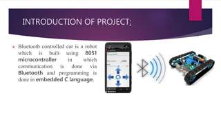
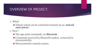
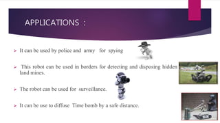
A
PRESENTATION
ON
BLUETOOTH CONTROLLED ROBOT
PRESENTED BY: GUIDED BY
AAYUSHI (1228231002) MR.JITENDRA SHARMA
SHIVANI (1228231008) (ASSITANT PROFESSIOR )
PRIYANKA (1328231902)
SUMIT(1228231016)
JP INSTITUTE OF ENGINEERING & TECHNOLOGY,
MEERUT
Wireless Bluetooth control robot
TABLE OF CONTENTS:
 INTRODUCTION OF PROJECT
 BLOCK DIAGRAM
 OVERVIEW OF PROJECT
 COMPONENT USED IN PROJECT
 MICRO CONTROLLER
 PIN DISCRIPTION
 BLUETOOTH
 MOTOR
 POWER SUPPLY
 SOFTWARE USED
INTRODUCTION OF PROJECT:
 Bluetooth controlled car is a robot
which is built using 8051
microcontroller in which
communication is done via
Bluetooth and programming is
done in embedded C language.
OVERVIEW OF PROJECT:
 What?
 Vehicle which can be controlled remotely by an Android
smart phone.
 How?
 The app sends commands via Bluetooth.
 Commands received by Bluetooth modem connected to
microcontroller.
 Microcontroller controls motors.
BLOCK DIAGRAM:
MICROCONTROLLER:
 Introduced in 1981 by Intel corp.
 8 bit microcontroller.
 4K bytes internal ROM.
 128 bytes internal RAM.
 Four 8-bit I/O ports (P0 - P3).
All four ports are bidirectional.
 Max. of 64k bytes of on chip ROM.
PIN DISCRIPTION OF 8051 MICROPROSESSOR :
CONT::
 There are 40 pins which are dedicated to several functions such as
I/O, address, RD, WR, data and interrupts.
 A total of 32 pins are set away into four ports such as P0, P1, P2,
and P3. Where each port contains 8 pins.
 XTAL1, XTAL2: X2 AND X1 pins are input output pins for the
oscillator. These pins are used to connect to the microcontroller.
 PSEN: This pin is used to enable external program memory. If we
use an external ROM for storing the program, then logic 0 appears
on it, which indicates microcontroller to read data from the
memory.
CONT::
 ALE: Address latch enable pin is an active high –output signals. If
we use multiple memory chips, then this pin is used to distinguish
between them.
 EA: It have to use multiple memories then the application of logic 1
to this pin instructs the microcontroller to read data from both
memories –first internal and then external.
BLUETOOTH:
 Bluetooth Technology is standard for short-range radio communication.
 It is a low cost bi-directional (2 ways) wireless interface between
mobile devices that provides low power consumption.
 Bluetooth Transceiver referring to Bluetooth Transmitter and Receiver
and every Bluetooth node have Bluetooth Transceiver.
CONT::
 The aim is to eliminate the usage of cables. Bluetooth
system operates in worldwide unlicensed 2.4GHz
Industrial-Scientific-Medical (ISM) frequency band.
Bluetooth devices can form a network.
MOTOR:
 Motor control requires full processor attention
Monitor motor speed
Continuously adjust motor voltage to minimize error
between desired and actual motor speeds
Essentially a digital feedback control system
 Want to avoid this additional hardware and software
complexity.
POWER SUPPLY
 A device or system that supplies electrical or other types of energy to an
output load or group of loads is called a power supply unit or PSU.
 Here in our application we need a 12v DC power supply for all
electronics involved in the project.
 This requires step down transformer, rectifier, voltage regulator, and
filter circuit for generation of 12v DC power.
SOFTWARE USED:
 Kiel Software to provide you with software development tools for
8051 based microcontrollers.
 With the Kiel tools, you can generate embedded applications for
virtually every 8051 derivative.
 Kiel software converts the C-codes into the Intel Hex code.
APPLICATIONS :
 It can be used by police and army for spying
 This robot can be used in borders for detecting and disposing hidden
land mines.
 The robot can be used for surveillance.
 It can be use to diffuse Time bomb by a safe distance.
ADVANTAGES:
 The robot is small in size it easy to carry .
 Bluetooth is actually cheap technology which help to reduce
the cost of project
 It need to low power for working so it is Low energy
consumption device
 It can operate by remote a long distance
 This device has low weight so it run faster
FUTURE DEVELOPMENT:
 We can interface sensor to this robot so that it can monitor some
parameters.
 We can add wireless camera to this robot.
 IT can be powered by solar energy
 IT can be used radar system to see the objective inside a building
REFRENCE:-:
QUESTION & ANSWER SESSION:-:
Robo wireless controll

Robo wireless controll

  • 1.
    A PRESENTATION ON BLUETOOTH CONTROLLED ROBOT PRESENTEDBY: GUIDED BY AAYUSHI (1228231002) MR.JITENDRA SHARMA SHIVANI (1228231008) (ASSITANT PROFESSIOR ) PRIYANKA (1328231902) SUMIT(1228231016) JP INSTITUTE OF ENGINEERING & TECHNOLOGY, MEERUT
  • 2.
  • 3.
    TABLE OF CONTENTS: INTRODUCTION OF PROJECT  BLOCK DIAGRAM  OVERVIEW OF PROJECT  COMPONENT USED IN PROJECT  MICRO CONTROLLER  PIN DISCRIPTION  BLUETOOTH  MOTOR  POWER SUPPLY  SOFTWARE USED
  • 4.
    INTRODUCTION OF PROJECT: Bluetooth controlled car is a robot which is built using 8051 microcontroller in which communication is done via Bluetooth and programming is done in embedded C language.
  • 5.
    OVERVIEW OF PROJECT: What?  Vehicle which can be controlled remotely by an Android smart phone.  How?  The app sends commands via Bluetooth.  Commands received by Bluetooth modem connected to microcontroller.  Microcontroller controls motors.
  • 6.
  • 7.
    MICROCONTROLLER:  Introduced in1981 by Intel corp.  8 bit microcontroller.  4K bytes internal ROM.  128 bytes internal RAM.  Four 8-bit I/O ports (P0 - P3). All four ports are bidirectional.  Max. of 64k bytes of on chip ROM.
  • 8.
    PIN DISCRIPTION OF8051 MICROPROSESSOR :
  • 9.
    CONT::  There are40 pins which are dedicated to several functions such as I/O, address, RD, WR, data and interrupts.  A total of 32 pins are set away into four ports such as P0, P1, P2, and P3. Where each port contains 8 pins.  XTAL1, XTAL2: X2 AND X1 pins are input output pins for the oscillator. These pins are used to connect to the microcontroller.  PSEN: This pin is used to enable external program memory. If we use an external ROM for storing the program, then logic 0 appears on it, which indicates microcontroller to read data from the memory.
  • 10.
    CONT::  ALE: Addresslatch enable pin is an active high –output signals. If we use multiple memory chips, then this pin is used to distinguish between them.  EA: It have to use multiple memories then the application of logic 1 to this pin instructs the microcontroller to read data from both memories –first internal and then external.
  • 11.
    BLUETOOTH:  Bluetooth Technologyis standard for short-range radio communication.  It is a low cost bi-directional (2 ways) wireless interface between mobile devices that provides low power consumption.  Bluetooth Transceiver referring to Bluetooth Transmitter and Receiver and every Bluetooth node have Bluetooth Transceiver.
  • 12.
    CONT::  The aimis to eliminate the usage of cables. Bluetooth system operates in worldwide unlicensed 2.4GHz Industrial-Scientific-Medical (ISM) frequency band. Bluetooth devices can form a network.
  • 13.
    MOTOR:  Motor controlrequires full processor attention Monitor motor speed Continuously adjust motor voltage to minimize error between desired and actual motor speeds Essentially a digital feedback control system  Want to avoid this additional hardware and software complexity.
  • 14.
    POWER SUPPLY  Adevice or system that supplies electrical or other types of energy to an output load or group of loads is called a power supply unit or PSU.  Here in our application we need a 12v DC power supply for all electronics involved in the project.  This requires step down transformer, rectifier, voltage regulator, and filter circuit for generation of 12v DC power.
  • 15.
    SOFTWARE USED:  KielSoftware to provide you with software development tools for 8051 based microcontrollers.  With the Kiel tools, you can generate embedded applications for virtually every 8051 derivative.  Kiel software converts the C-codes into the Intel Hex code.
  • 16.
    APPLICATIONS :  Itcan be used by police and army for spying  This robot can be used in borders for detecting and disposing hidden land mines.  The robot can be used for surveillance.  It can be use to diffuse Time bomb by a safe distance.
  • 17.
    ADVANTAGES:  The robotis small in size it easy to carry .  Bluetooth is actually cheap technology which help to reduce the cost of project  It need to low power for working so it is Low energy consumption device  It can operate by remote a long distance  This device has low weight so it run faster
  • 18.
    FUTURE DEVELOPMENT:  Wecan interface sensor to this robot so that it can monitor some parameters.  We can add wireless camera to this robot.  IT can be powered by solar energy  IT can be used radar system to see the objective inside a building
  • 19.
  • 20.