Downloaded 852 times
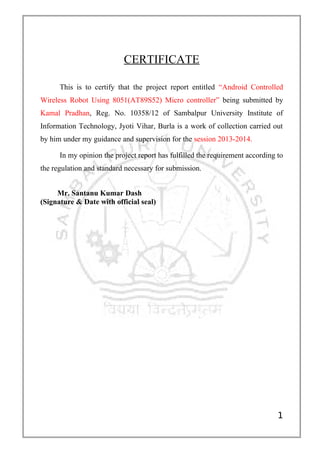

This document is a certificate certifying that Kamal Pradhan completed a project report entitled "Android Controlled Wireless Robot Using 8051(AT89S52) Micro controller" under the guidance of Mr. Santanu Kumar Dash for the 2013-2014 session. The project report fulfills the necessary requirements and regulations for submission. Kamal Pradhan thanks various people who helped with the project including his guide Mr. Dash and director Prof. S.S. Pujari.