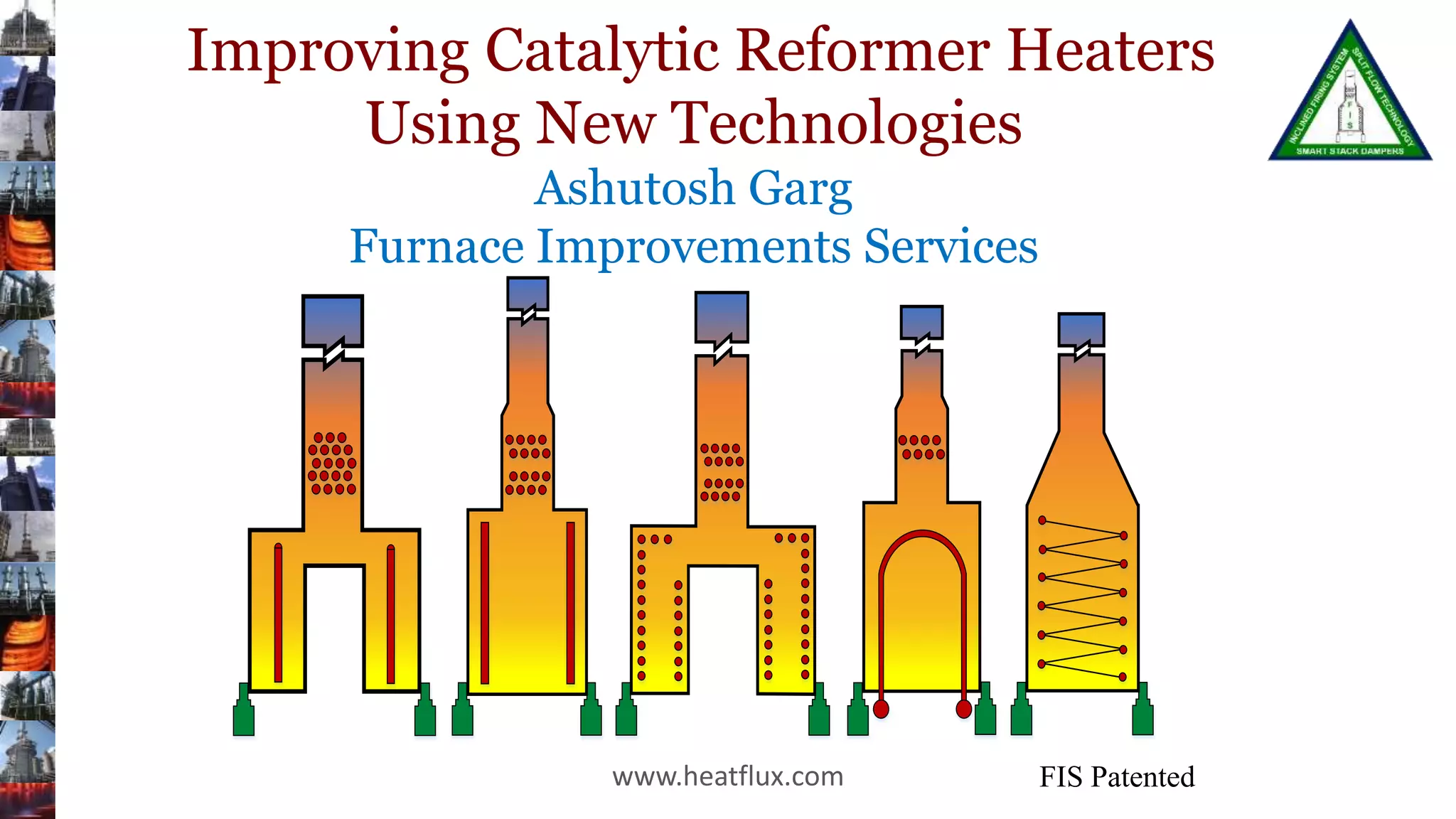
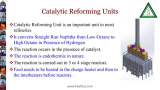
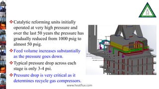
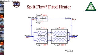
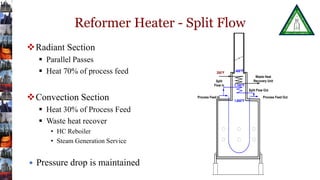
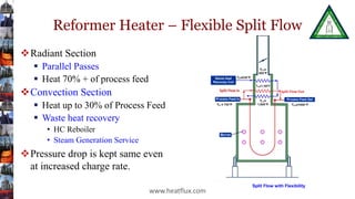
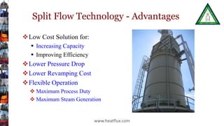
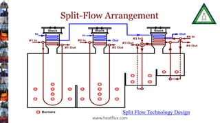
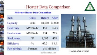
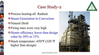
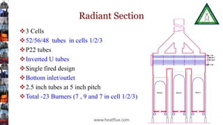
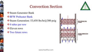
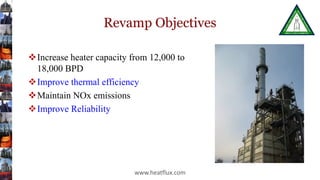
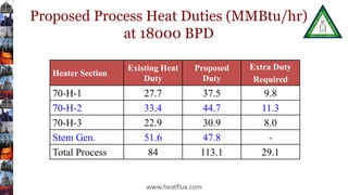
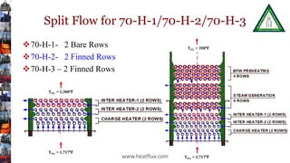
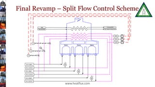
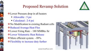
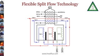
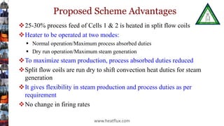
www.heatflux.com
Improving Catalytic Reformer Heaters
Using New Technologies
Ashutosh Garg
Furnace Improvements Services
www.heatflux.com
FIS Patented
Catalytic Reforming Units
Catalytic Reforming Unit is an important unit in most
refineries
It converts Straight Run Naphtha from Low Octane to
High Octane in Presence of Hydrogen
The reaction occurs in the presence of catalyst.
The reaction is endothermic in nature.
The reaction is carried out in 3 or 4 stage reactors.
Feed needs to be heated in the charge heater and then to
the interheaters before reactors.
www.heatflux.com
Catalytic reforming units initially
operated at very high pressure and
over the last 50 years the pressure has
gradually reduced from 1000 psig to
almost 50 psig.
Feed volume increases substantially
as the pressure goes down.
Typical pressure drop across each
stage is only 3-4 psi.
Pressure drop is very critical as it
determines recycle gas compressors.
www.heatflux.com
Catalytic Reforming Heaters
Most of the heaters have charge in the radiant
section only
 Inlet all vapor, large manifolds provided
 Low pressure drop required, multiple passes
 High inlet temperature 850-900 F, outlet temperature-
950-1050 F
Convection section has waste heat recovery
 Mostly steam generation –bfw preheating, steam
generation and steam superheater
 Some have stripper and stabilizer reboilers coils
www.heatflux.com
Construction
Most heaters are natural draft
configuration
Tall stack providing draft in the
radiant section
Air preheating also installed in
some heaters
Typical heat flux
15,000-20,000 Btu/hr.ft2
Tubes are single fired or double
fired
www.heatflux.com
Convection Section
Stack
Damper
Most Clients
want to
Increase
Heater Duty
Clients are want to increase the
capacity of their units
Increase in charge rate means increase
of pressure drop in the heater
Limited in pressure drop and cannot
push more charge
Limited in firing rate/permit limit
www.heatflux.com
Conventional Approach
Increase tube size to reduce pressure drop
Upgrade tube metallurgy to increase TMT limits
Both options require complete radiant section
retubing including manifold
Increase heat transfer area in radiant section
 Extend existing radiant section
 Add new radiant section
Both these options are extremely expensive
www.heatflux.com
Process Feed In
Process Feed Out
Waste Heat
Recovery Unit
1,600°F
750°F
250°F
750°F
1000°F
Conventional Approach to Increasing Capacity
 Extend radiant cell and add more radiant coils & burners
 Provide additional radiant cells with new coils and burners
H-20
H-21
H-22
H-20
(NEW)
H-21
(NEW)
H-21
(NEW)
H-20 H-21 H-22
www.heatflux.com
Drawbacks of
Conventional
Approach
Real estate
requirement
New burners
& associated
changes
New civil
foundation
work
Higher firing
rates
Draft
limitation
Very High cost
www.heatflux.com
Split Flow* Fired Heater
www.heatflux.com10
*Patented
Feed In Feed Out
450 °F 600 °F
Radiant Section
Convection
Section - I
1,650 °FFlue gas 3,200 °FFlue gas
1,650 °FFlue gas
500 °F
Convection
Section- II
750 °FFlue gas
Flue gas
Flue gas
Split Flow in
Split Flow out
450 °F 600 °F
500 °F
Reformer Heater - Split Flow
Radiant Section
 Parallel Passes
 Heat 70% of process feed
Convection Section
 Heat 30% of Process Feed
 Waste heat recover
• HC Reboiler
• Steam Generation Service
 Pressure drop is maintained
11
Process Feed In Process Feed Out
Split
Flow in
Split Flow Out
Waste Heat
Recovery Unit
1,600°F
1,100°F
250°F
400°F
Reformer Heater – Flexible Split Flow
Radiant Section
 Parallel Passes
 Heat 70% + of process feed
Convection Section
 Heat up to 30% of Process Feed
 Waste heat recovery
• HC Reboiler
• Steam Generation Service
Pressure drop is kept same even
at increased charge rate.
www.heatflux.com
Split Flow with Flexibility
Split Flow Technology - Advantages
Low Cost Solution for:
 Increasing Capacity
 Improving Efficiency
Lower Pressure Drop
Lower Revamping Cost
Flexible Operation
 Maximum Process Duty
 Maximum Steam Generation
www.heatflux.com
Case Study 1
Three stage catalytic reformer ( reactor) unit
First cell – Feed heater, Rest 3 cells- interheater
Feed- Mixture of Naphtha and Recycle gas
Inlet Temperature- 842-990 °F
Outlet Temperature-1010 °F
Inlet Pressure-231 psig
Outlet Pressure- 228 psig
Pressure drop /stage- 3 psi
www.heatflux.com
Revamp Objectives
Improve Efficiency
 Stack temperature was 1100 ºF
 No steam generation
 No air preheater
Gas prices touched
$10/MSCF
www.heatflux.com
Arrangement - Original Heater
Process flow before revamp
StackStackStack
Stabilizer
Btms
Stabilizer
Btms
Stripper Btms
Stripper Btms
To Plat. RX To Plat. RX
From Plat. RX.
To Plat. RX
From Plat. RX
Stripper Btms
From Plat.
RX
To Plat. RX
Stripper Btms
BURNERS
428°F
840°F
459°F
1010°F
www.heatflux.com
Reformer Heater Conventional
Revamp
Increase heat transfer surface in
convection section
Pressure drop – more than twice
of existing
Large size piping requirement
Larger convection sections
Increased stack height
High cost ($6 Million) Reformer Heater
www.heatflux.com
Split-Flow Arrangement
Split Flow Technology Design
StackStackStack
Burners
#1 In
#1 Out
In
#2 In
#2 Out
#3 In
#3 Out
#4 In
#4 Out
In
Out
Out
www.heatflux.com
Heater Data Comparison
Heater after revamp
Reformer Heater Data Comparison
Item Units Before After
Capacity BPD 18,500 24,000
Heat Duty MMBtu/hr 158 194.5
Heat release MMBtu/hr 234 225
Stack temp. °F 1,092 478
Efficiency % 67.5 86.6
Fuel savings $/annum 5.8 Million
www.heatflux.com
Case Study-2
Process heating-all Radiant
Steam Generation in Convection
Natural Draft
Firing rates were very high
Heater efficiency lower than design
value by 10% to 15%
Stack temperature -650℉ (320 ℉
higher than design)
www.heatflux.com
Radiant Section
3 Cells
52/56/48 tubes in cells 1/2/3
P22 tubes
Inverted U tubes
Single fired design
Bottom inlet/outlet
2.5 inch tubes at 5 inch pitch
Total -23 Burners (7 , 9 and 7 in cell 1/2/3)
www.heatflux.com
Convection Section
Steam Generator Bank
BFW Preheater Bank
Steam Generation: 53,650 lbs/hr@300 psig
8 tubes per row
Eleven rows
Two future rows
www.heatflux.com
Revamp Objectives
Increase heater capacity from 12,000 to
18,000 BPD
Improve thermal efficiency
Maintain NOx emissions
Improve Reliability
www.heatflux.com
Proposed Process Heat Duties (MMBtu/hr)
at 18000 BPD
Heater Section
Existing Heat
Duty
Proposed
Duty
Extra Duty
Required
70-H-1 27.7 37.5 9.8
70-H-2 33.4 44.7 11.3
70-H-3 22.9 30.9 8.0
Stem Gen. 51.6 47.8 -
Total Process 84 113.1 29.1
www.heatflux.com
Split Flow for 70-H-1/70-H-2/70-H-3
70-H-1- 2 Bare Rows
70-H-2- 2 Finned Rows
70-H-3 – 2 Finned Rows
TFG = 1,717℉
TFG = 1,300℉
TFG = 350℉
TFG = 1,717℉www.heatflux.com
Final Revamp – Split Flow Control Scheme
www.heatflux.com
Proposed Revamp Solution
Lower Pressure drop in all heaters
 Allowable : 5 psi
 Calculated : 2-4 psi
No Modification to existing Radiant cells
Reduced Average Heat Flux
Lower Firing Rate – 180 MMBtu /hr
Lower Volumetric Heat Release
More efficient system - 89%
Flexibility to increase duty further
www.heatflux.com
Flexible Split Flow Technology
www.heatflux.com
Proposed Scheme Advantages
25-30% process feed of Cells 1 & 2 is heated in split flow coils
Heater to be operated at two modes:
 Normal operation/Maximum process absorbed duties
 Dry run operation/Maximum steam generation
To maximize steam production, process absorbed duties reduced
Split flow coils are run dry to shift convection heat duties for steam
generation
It gives flexibility in steam production and process duties as per
requirement
No change in firing rates
www.heatflux.com
General Advantages of FIS
Flexible Split Flow Technology
Improved Capacity and Flexible Operation
Higher Efficiency
Lower Pressure Drop (process)
Lower Firing Rate
Lower Fire Box Temperatures
Lower Radiant Heat Fluxes
Lower TMT
Lower Turnaround Time
Lower Installation Cost
www.heatflux.com
www.heatflux.com
Furnace Improvement Services Inc.
Low Cost Solutions for Fired Heaters and Boilers
1600 Hwy 6 South Ste. 480
Sugar Land, TX 77479
Tel: (281) 980-0325
www.heatflux.com
Thank you very much.
Questions and Comments are welcome.

AIChE 2018 improving catalytic reformer heaters using split flow technology rev2

  • 1.
    www.heatflux.com Improving Catalytic ReformerHeaters Using New Technologies Ashutosh Garg Furnace Improvements Services www.heatflux.com FIS Patented
  • 2.
    Catalytic Reforming Units CatalyticReforming Unit is an important unit in most refineries It converts Straight Run Naphtha from Low Octane to High Octane in Presence of Hydrogen The reaction occurs in the presence of catalyst. The reaction is endothermic in nature. The reaction is carried out in 3 or 4 stage reactors. Feed needs to be heated in the charge heater and then to the interheaters before reactors. www.heatflux.com
  • 3.
    Catalytic reforming unitsinitially operated at very high pressure and over the last 50 years the pressure has gradually reduced from 1000 psig to almost 50 psig. Feed volume increases substantially as the pressure goes down. Typical pressure drop across each stage is only 3-4 psi. Pressure drop is very critical as it determines recycle gas compressors. www.heatflux.com
  • 4.
    Catalytic Reforming Heaters Mostof the heaters have charge in the radiant section only  Inlet all vapor, large manifolds provided  Low pressure drop required, multiple passes  High inlet temperature 850-900 F, outlet temperature- 950-1050 F Convection section has waste heat recovery  Mostly steam generation –bfw preheating, steam generation and steam superheater  Some have stripper and stabilizer reboilers coils www.heatflux.com
  • 5.
    Construction Most heaters arenatural draft configuration Tall stack providing draft in the radiant section Air preheating also installed in some heaters Typical heat flux 15,000-20,000 Btu/hr.ft2 Tubes are single fired or double fired www.heatflux.com Convection Section Stack Damper
  • 6.
    Most Clients want to Increase HeaterDuty Clients are want to increase the capacity of their units Increase in charge rate means increase of pressure drop in the heater Limited in pressure drop and cannot push more charge Limited in firing rate/permit limit www.heatflux.com
  • 7.
    Conventional Approach Increase tubesize to reduce pressure drop Upgrade tube metallurgy to increase TMT limits Both options require complete radiant section retubing including manifold Increase heat transfer area in radiant section  Extend existing radiant section  Add new radiant section Both these options are extremely expensive www.heatflux.com Process Feed In Process Feed Out Waste Heat Recovery Unit 1,600°F 750°F 250°F 750°F 1000°F
  • 8.
    Conventional Approach toIncreasing Capacity  Extend radiant cell and add more radiant coils & burners  Provide additional radiant cells with new coils and burners H-20 H-21 H-22 H-20 (NEW) H-21 (NEW) H-21 (NEW) H-20 H-21 H-22 www.heatflux.com
  • 9.
    Drawbacks of Conventional Approach Real estate requirement Newburners & associated changes New civil foundation work Higher firing rates Draft limitation Very High cost www.heatflux.com
  • 10.
    Split Flow* FiredHeater www.heatflux.com10 *Patented Feed In Feed Out 450 °F 600 °F Radiant Section Convection Section - I 1,650 °FFlue gas 3,200 °FFlue gas 1,650 °FFlue gas 500 °F Convection Section- II 750 °FFlue gas Flue gas Flue gas Split Flow in Split Flow out 450 °F 600 °F 500 °F
  • 11.
    Reformer Heater -Split Flow Radiant Section  Parallel Passes  Heat 70% of process feed Convection Section  Heat 30% of Process Feed  Waste heat recover • HC Reboiler • Steam Generation Service  Pressure drop is maintained 11 Process Feed In Process Feed Out Split Flow in Split Flow Out Waste Heat Recovery Unit 1,600°F 1,100°F 250°F 400°F
  • 12.
    Reformer Heater –Flexible Split Flow Radiant Section  Parallel Passes  Heat 70% + of process feed Convection Section  Heat up to 30% of Process Feed  Waste heat recovery • HC Reboiler • Steam Generation Service Pressure drop is kept same even at increased charge rate. www.heatflux.com Split Flow with Flexibility
  • 13.
    Split Flow Technology- Advantages Low Cost Solution for:  Increasing Capacity  Improving Efficiency Lower Pressure Drop Lower Revamping Cost Flexible Operation  Maximum Process Duty  Maximum Steam Generation www.heatflux.com
  • 14.
    Case Study 1 Threestage catalytic reformer ( reactor) unit First cell – Feed heater, Rest 3 cells- interheater Feed- Mixture of Naphtha and Recycle gas Inlet Temperature- 842-990 °F Outlet Temperature-1010 °F Inlet Pressure-231 psig Outlet Pressure- 228 psig Pressure drop /stage- 3 psi www.heatflux.com
  • 15.
    Revamp Objectives Improve Efficiency Stack temperature was 1100 ºF  No steam generation  No air preheater Gas prices touched $10/MSCF www.heatflux.com
  • 16.
    Arrangement - OriginalHeater Process flow before revamp StackStackStack Stabilizer Btms Stabilizer Btms Stripper Btms Stripper Btms To Plat. RX To Plat. RX From Plat. RX. To Plat. RX From Plat. RX Stripper Btms From Plat. RX To Plat. RX Stripper Btms BURNERS 428°F 840°F 459°F 1010°F www.heatflux.com
  • 17.
    Reformer Heater Conventional Revamp Increaseheat transfer surface in convection section Pressure drop – more than twice of existing Large size piping requirement Larger convection sections Increased stack height High cost ($6 Million) Reformer Heater www.heatflux.com
  • 18.
    Split-Flow Arrangement Split FlowTechnology Design StackStackStack Burners #1 In #1 Out In #2 In #2 Out #3 In #3 Out #4 In #4 Out In Out Out www.heatflux.com
  • 19.
    Heater Data Comparison Heaterafter revamp Reformer Heater Data Comparison Item Units Before After Capacity BPD 18,500 24,000 Heat Duty MMBtu/hr 158 194.5 Heat release MMBtu/hr 234 225 Stack temp. °F 1,092 478 Efficiency % 67.5 86.6 Fuel savings $/annum 5.8 Million www.heatflux.com
  • 20.
    Case Study-2 Process heating-allRadiant Steam Generation in Convection Natural Draft Firing rates were very high Heater efficiency lower than design value by 10% to 15% Stack temperature -650℉ (320 ℉ higher than design) www.heatflux.com
  • 21.
    Radiant Section 3 Cells 52/56/48tubes in cells 1/2/3 P22 tubes Inverted U tubes Single fired design Bottom inlet/outlet 2.5 inch tubes at 5 inch pitch Total -23 Burners (7 , 9 and 7 in cell 1/2/3) www.heatflux.com
  • 22.
    Convection Section Steam GeneratorBank BFW Preheater Bank Steam Generation: 53,650 lbs/hr@300 psig 8 tubes per row Eleven rows Two future rows www.heatflux.com
  • 23.
    Revamp Objectives Increase heatercapacity from 12,000 to 18,000 BPD Improve thermal efficiency Maintain NOx emissions Improve Reliability www.heatflux.com
  • 24.
    Proposed Process HeatDuties (MMBtu/hr) at 18000 BPD Heater Section Existing Heat Duty Proposed Duty Extra Duty Required 70-H-1 27.7 37.5 9.8 70-H-2 33.4 44.7 11.3 70-H-3 22.9 30.9 8.0 Stem Gen. 51.6 47.8 - Total Process 84 113.1 29.1 www.heatflux.com
  • 25.
    Split Flow for70-H-1/70-H-2/70-H-3 70-H-1- 2 Bare Rows 70-H-2- 2 Finned Rows 70-H-3 – 2 Finned Rows TFG = 1,717℉ TFG = 1,300℉ TFG = 350℉ TFG = 1,717℉www.heatflux.com
  • 26.
    Final Revamp –Split Flow Control Scheme www.heatflux.com
  • 27.
    Proposed Revamp Solution LowerPressure drop in all heaters  Allowable : 5 psi  Calculated : 2-4 psi No Modification to existing Radiant cells Reduced Average Heat Flux Lower Firing Rate – 180 MMBtu /hr Lower Volumetric Heat Release More efficient system - 89% Flexibility to increase duty further www.heatflux.com
  • 28.
    Flexible Split FlowTechnology www.heatflux.com
  • 29.
    Proposed Scheme Advantages 25-30%process feed of Cells 1 & 2 is heated in split flow coils Heater to be operated at two modes:  Normal operation/Maximum process absorbed duties  Dry run operation/Maximum steam generation To maximize steam production, process absorbed duties reduced Split flow coils are run dry to shift convection heat duties for steam generation It gives flexibility in steam production and process duties as per requirement No change in firing rates www.heatflux.com
  • 30.
    General Advantages ofFIS Flexible Split Flow Technology Improved Capacity and Flexible Operation Higher Efficiency Lower Pressure Drop (process) Lower Firing Rate Lower Fire Box Temperatures Lower Radiant Heat Fluxes Lower TMT Lower Turnaround Time Lower Installation Cost www.heatflux.com www.heatflux.com
  • 31.
    Furnace Improvement ServicesInc. Low Cost Solutions for Fired Heaters and Boilers 1600 Hwy 6 South Ste. 480 Sugar Land, TX 77479 Tel: (281) 980-0325 www.heatflux.com Thank you very much. Questions and Comments are welcome.