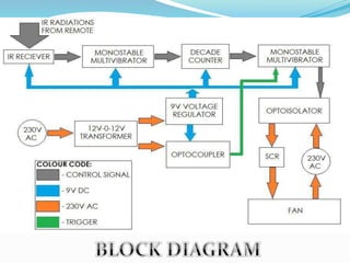
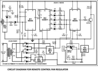
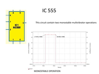
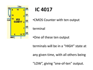
IT IS A SMALL PPT ABOUT REMOTE CONTROL REGULATOR.DAY BY DAY OUR TECHNOLOGY DEVELOPING SO SOME CHANGES ALSO HAPPEN USING REMOTE CONTROL REGULATOR WE CAN CONTROL ALL ELECTRONICS DEVICE USING REMOTE CONTROL REGULATOR.
Remote Controlled Home Appliance is a microcontroller based wireless system. we choose infrared to design the remote control system for home appliances for our project. Here we used IR Transmitter (Commonly Used remotes for home appliances) and IR Sensor Modules The major aim of this project is to deliver the technology of modern world in our country at low price to general people. The overall performance of the power supply (PS) is excellent as a constant supply to drive any small load
This PPT explains about TV Remote Operated Domestic Appliances Control.
Edgefxkits.com has a wide range of electronic projects ideas that are primarily helpful for ECE, EEE and EIE students and the ideas can be applied for real life purposes as well.
http://www.edgefxkits.com/
Visit our page to get more ideas on popular electronic projects developed by professionals.
Edgefx provides free verified electronic projects kits around the world with abstracts, circuit diagrams, and free electronic software. We provide guidance manual for Do It Yourself Kits (DIY) with the modules at best price along with free shipping.
This is to design a circuit such that one can control home or industrial appliance using the help of remote. This circuit can be used to any of your home appliances (lamp, fan, radio, etc.) to make the appliance turn on/off from a TV remote control.
Using remote to control appliances reduces human efforts without compromising on efficiency. It also saves time. Infrared (IR) light is an electromagnetic radiation with a wavelength longer than that of visible light, measured from the nominal edge of visible red light at 0.7 μm and extending conventionally to 300 μm,. These radiations with a frequency below our eyes sensitivity cannot be seen, but can only be felt by our skin temperature sensors. Infrared is interesting, because it is easily generated and doesn't suffer electromagnetic interference and so it is widely used in communication and control circuits. The adventure of using lots of infrared in TV remote controls helped engineers to work on innovative projects like controlling home appliances using TV remotes etc. Receiver in the circuit receives pulsed IR rays from the remote and decoded signal is thus received by relay driver whose output activates the corresponding home appliance. According to this, it makes sense that the logical direction about managing home appliances (HASs) in the near future is going to be by means of a remote control. But wireless technologies in domestics should be implemented carefully.
It is a minor project on how a dook knock alarm works.Is shows how one form of energy is transferred to another form of energy which follows the law of conservation of energy
Here is a circuit through which the
speed of a fan can be linearly controlled
automatically, depending
on the room temperature. The circuit is
highly efficient as it uses thyristors for
power control. Alternatively, the same
circuit can be used for automatic temperature
controlled AC power control.
In this circuit, the temperature sensor
used is an NTC thermistor, i.e. one having
a negative temperature coefficient. The
value of thermistor resistance at 25°C is
about 1 kilo-ohm.
Op-amp A1 essentially works as
I to V (current-to-voltage) converter
and converts temperature variations
into voltage variations. To amplify
the change in voltage due to change in
temperature, instrumentation amplifier
formed by op-amps A2, A3 and A4
is used. Resistor R2 and zener diode
D1 combination is used for generating
reference voltage as we want to amplify
only change in voltage due to the
change in temperature.
Op-amp μA741 (IC2) works as a
comparator. One input to the comparator
is the output from the instrumentation
amplifier while the other input
is the stepped down, rectified and
suitably attenuated sample of AC voltage.
This is a negative going pulsating
DC voltage. It will be observed that
with increase in temperature, pin 2 of
IC2 goes more and more negative and
hence the width of the positive going
output pulses (at pin 6) increases linearly
with the temperature. Thus IC2
functions as a pulse width modulator
in this circuit. The output from the
comparator is coupled to an optocoupler,
which in turn controls the AC
power delivered to fan (load).
The circuit has a high sensitivity and
the output RMS voltage (across load) can
be varied from 120V to 230V (for a temp.
range of 22°C to 36°C), and hence wide
variations in speed are available. Also
note that speed varies linearly and not
in steps. Besides, since an optocoupler is
used, the control circuit is fully isolated
from power circuit, thus providing added
safety. Note that for any given temperature
the speed of fan (i.e. voltage across
load) can be adjusted to a desired value
by adjusting potmeters VR1 and VR2
appropriately.
Potmeter VR1 should he initially kept
in its mid position to realise a gain of approximately
40 from the instrumentation
amplifier. It may be subsequently trimmed
slightly to obtain linear variation of the
fan speed.
solar battery Charger using adapter or solar panelSwedel D'souza
For Circuit diagram ,kindly use this site,though we made few modification please refer to slide as well
also download proteus 8 for simulation of circuit
http://electrical-engineering-world1.blogspot.in/2015/02/how-to-make-6v-solar-battery-charger.html
refer this site for project
http://swedeljennifer.simplesite.com/
Infrared IR Sensor Circuit Diagram and Working Principleelprocus
An infrared sensor is an electronic device, that emits in order to sense some aspects of the surroundings. An IR sensor can measure the heat of an object as well as detects the motion. These types of sensors measures only infrared radiation, rather than emitting it that is called as a passive IR sensor. Usually in the infrared spectrum, all the objects radiate some form of thermal radiations.
Micro controller based Traffic control systemRohit Kumar
This project deals with traffic system controlled by a microcontroller.
using IR controllers instead of using old timing circuits.
This system aims to provide much better and safer way of controlling Traffic signal system.
This system of controlling will help a lot in future.
Our project “GSM based Garbage Disposal” is mainly intended to control the ON/OFF operations of the irrigation motor by using a mobile phone. The mobile phone present in the system uses auto answer function to lift the call. Each key in the mobile phone transmits two tones with different frequencies when pressed. These transmitted frequencies are decoded using DTMF decoder and the decoded value is fed as input to micro controller which in turn operates switches like Relay and Triac to which the irrigation motor is connected. The input value to the micro controller will be checked and respective operation of that key will be performed like switching ON/OFF the irrigation motor. The system also gives feed back through buzzer alarm system.
Voice recognition based home automation system for paralyzed peoplelal ahmed shaik
Automation is a trending topic in 21st century making an important role in our daily lives. Automation reduces the human labor, time, effort and some human errors. The key objective of our project is to design a system for physically handicapped persons to control and operate home appliances and their own wheel chair by their own voice. Both these qualities are present in our project which has the capability to replace existing technologies. the design of the low cost voice recognition based home automation system for the physically challenged people suffering from quadriplegia or paraplegia (who cannot move their limbs but can speak and listen) to control the various home appliances just by his/her voice commands according to their need and comfort. We also implemented a messaging concept. In this whenever the patient or the person needs a help, if he/she pronounce as help a message will be sent to their respective represented family member. The resultant system can provide a great assistance to the physically handicapped people without any need of third person.
TV Remote Jammer | 555 Timer Projects | Final Year Engineering ProjectsEdgefxkits & Solutions
This project is a simple but effective TV remote jammer that distracts the ir receiver in tv by using 555 timer. Rays are emitted by standard 38KHz Tv remote.
4. •Remote control simplified the control over equipment from a
distance without having to move around
•The system seeks to develop a system that is cost effective
while not under mining the need for efficiency.
•Zenith Electronics Corporation introduced the first remote
control, called “lazy bones” in 1950.
•The average person these days probably picks up a remote
control at least once or twice in an hour.
5. The operation of remote control can be divided in two parts;
a transmitter and a receiver.
The transistors within the transmitter amplify the signal and send them to the LED,
which translates the signal into infrared light.
The carrier frequency of such infrared signals is typically around 36 kHz.
The receiver consists of a sensor which detects the infrared light and
response appropriately to the received signal or command.
9. •CMOS Counter with ten output
terminal
•One of these ten output
terminals will be in a “HIGH” state at
any given time, with all others being
“LOW”, giving “one-of-ten” output.
IC 4017
10. •The circuit uses the whole bandwidth of remote IR,
and hence can be controlled by any kind remote.
•The range of remote IR is quite large. Thus the
regulator can be controlled across a large room.
•Even though we have used five speed levels, 10
different speed levels can be incorporated, with only
some minor changes. There is no subsequent cost
after the installation of the circuit.
•The circuit can be powered from the 230V AC line
itself.
11. •IR radiation from remotes is designed to
spread to large area. If the regulator sensor is
placed near the television/AC, then the fan
speed can be changed whenever the remote is
pressed for controlling the other device.
12. The IR remote controlled fan regulator is implemented using
IR sensor, monostable multivibrator, decade counter,
transformer, comparator, opto-isolator and TRIAC.
It is portable in size and the receiver responds only to the
infra-red signal transmitted by any modern day remote
control.
The system responds favourable and alters the voltage
smoothly when any button of modern day remote control is
pressed, irrespective of ac supply voltage frequency. The
receiver transmitter maximum distance is approximately 10m.