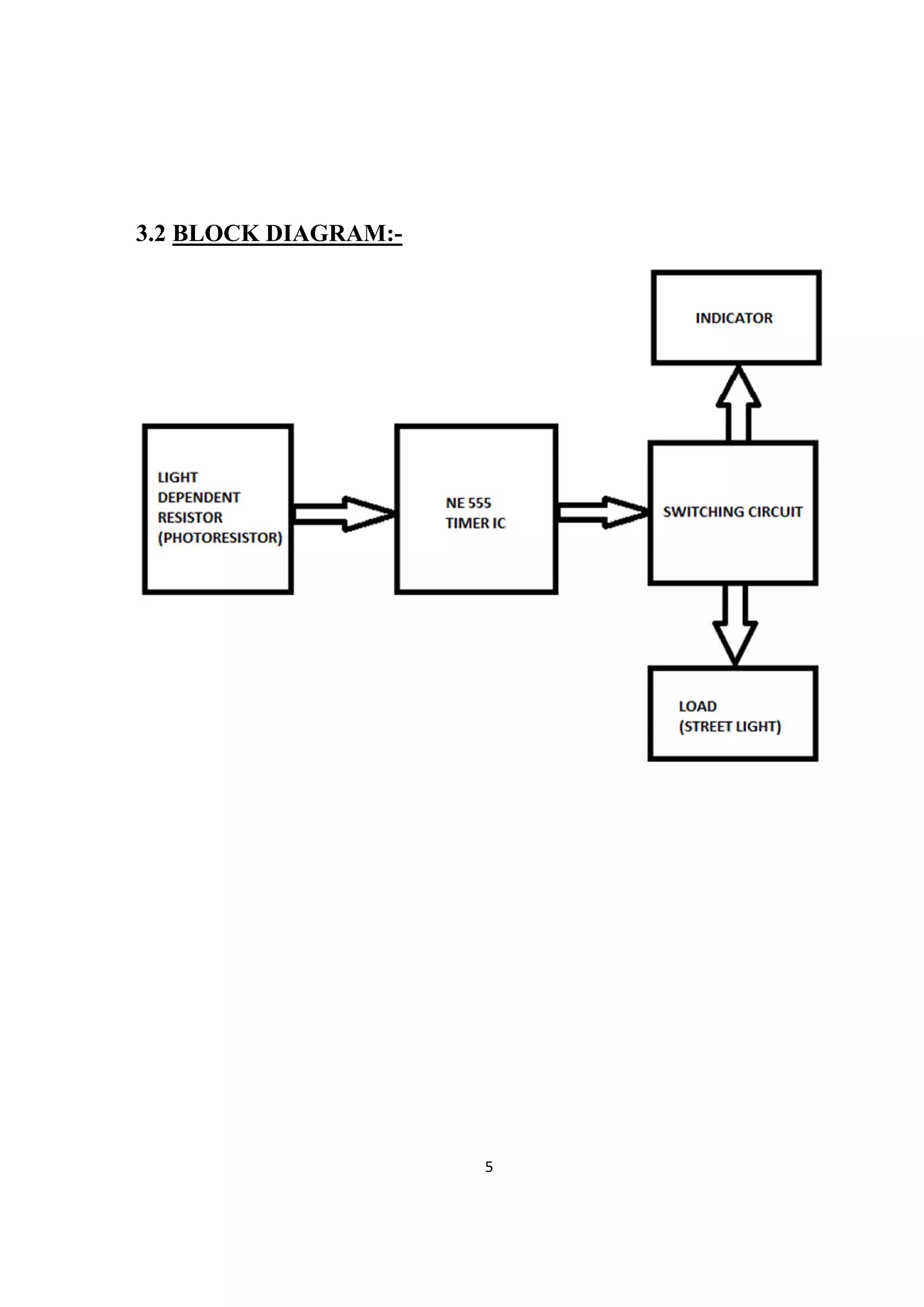
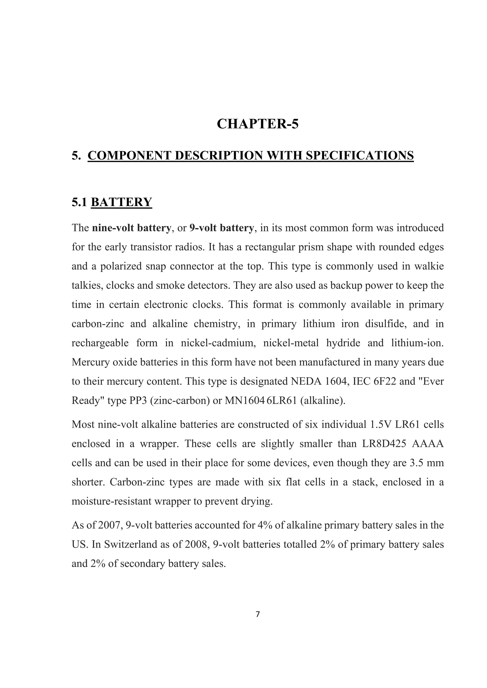
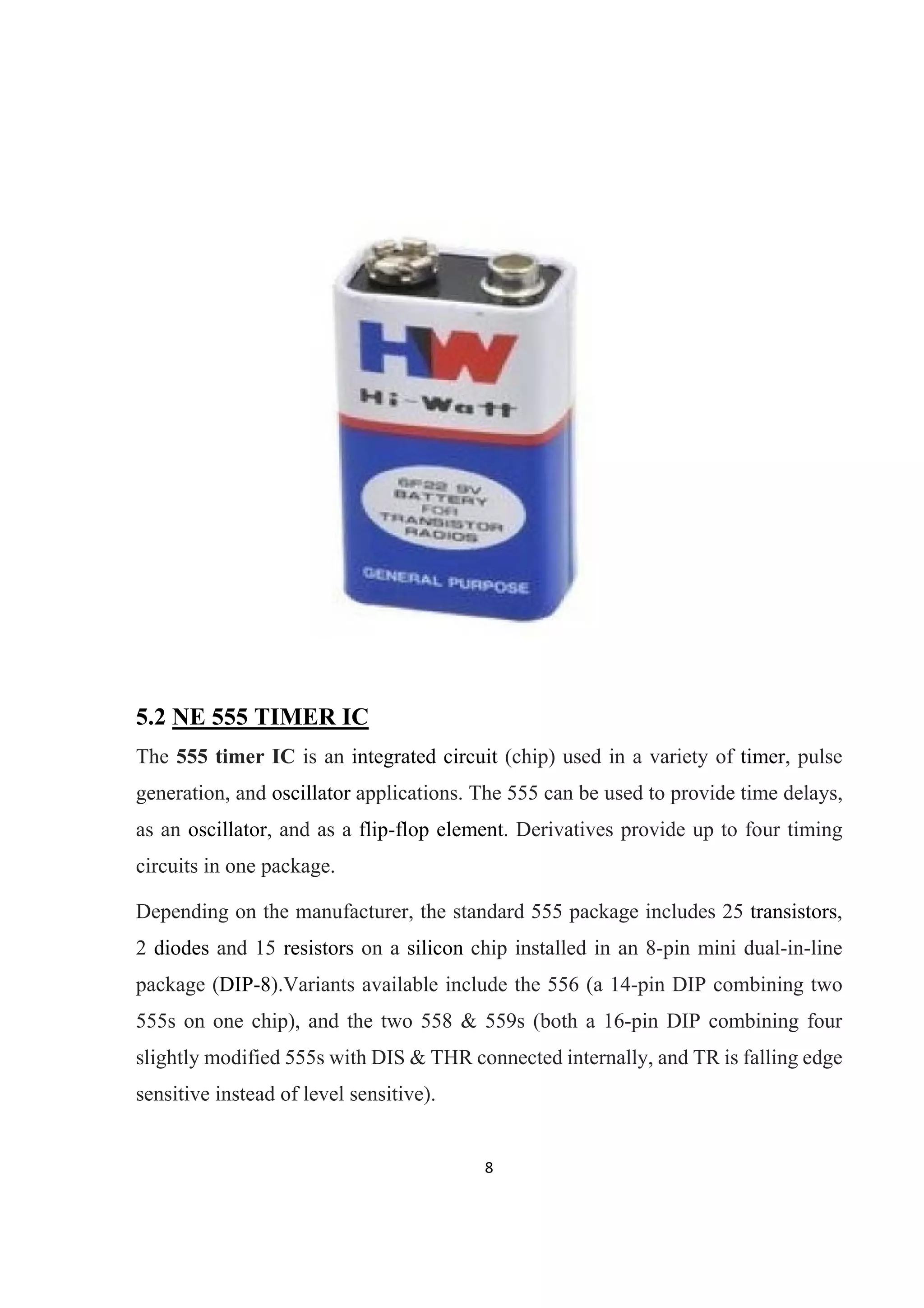
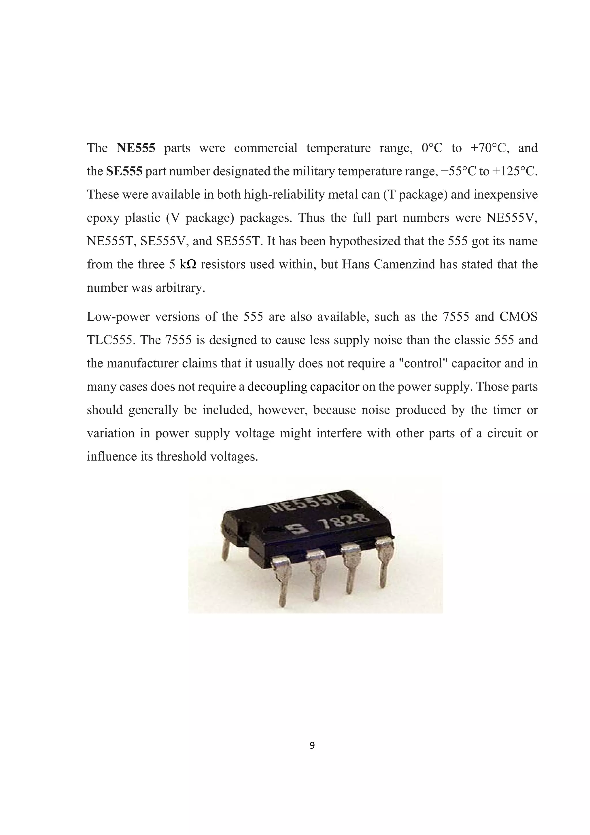
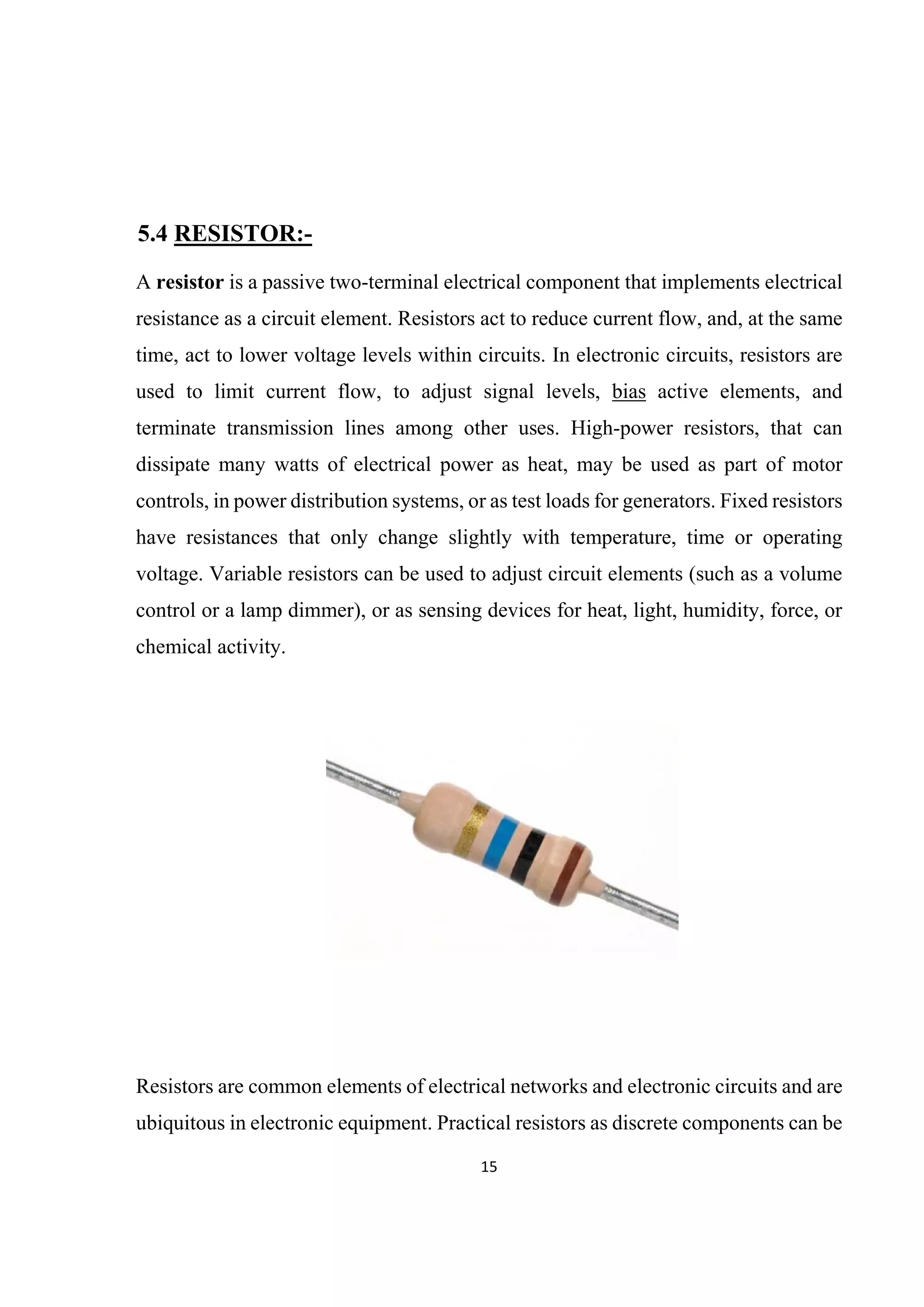
Many of the people have a phobia of darkness, so to assist them in such situation, we have explained a simple circuit. It will automatically turn on street light in the way of LEDs or bulb coupled with relay. Working this circuit is very much easy and also the power consumed by the circuit is very low because of the very few components used in the circuit.
Keypad is a common interface with any microcontroller. This presentation gives details of keypad can be interfaced with 8051. The key pressed may be dispalyed on LCD/7 segment/LED displays.
It is a minor project on how a dook knock alarm works.Is shows how one form of energy is transferred to another form of energy which follows the law of conservation of energy
We provide you Project Cell Phone Detector.You can choose the best of your choice and interest from the list of topics we suggested. All new project ideas that are appearing focuses to improve the knowledge of Engineering students.
https://www.elprocus.com
Visit our page to get more ideas on Project Report Format for Final Year Engineering Students these ideas developed by professionals.
Elprocus provides free verified electronic projects kits around the world with abstracts, circuit diagrams, and free electronic software. We provide guidance manual for Do It Yourself Kits (DIY) with the modules at best price along with free shipping.
This project aims at designing and executing the advanced development in embedded systems for energy saving of street lights with light depending resistor. Nowadays, human has become too busy and he is unable to find time even to switch the lights wherever not necessary. This can be seen more effectively in the case of street lights. The present system is like, the street lights will be switched on in the evening before the sun sets and they are switched off the next day morning after there is sufficient light on the roads. But the actual timings for these street lights to be switched on are when there is absolute darkness. With this, the power will be wasted up to some extent. This project gives the best solution for electrical power wastage. Also the manual operation of the lighting system is completely eliminated.
In our project we are using LDR, which varies according to the amount of light falling on its surface, this give an indication for us whether it is a day/night time. In the present project street lights are taken into consideration where the above discussed factors are rectified in them. This is achieved with the help of an embedded system. By using this as the basic principle we can design centralized intelligent system for the perfect usage of streetlights in any place (Village, Town) can be developed.
The design of an LED emergency light that switches on automatically when main power fails. Power to the LED is supplied by a battery that keeps charging when the main power is present. The circuit of the automatic LED light is designed, simulated and built with hardware. The simulation results and design details are provided. Complete circuit diagram, which is tested successfully, is given.
This paper explains the project which is a special kind of circular rotating 8 LED display. With the help some mechanical assembly, LED count, hardware requirement, and hence overall cost is cut to very affordable price and power is also saved. Also, maintenance and repairing of the display is so easy, that anyone having a little electronics knowledge can take care of this. All the synchronizing can be implemented through software. First of its kind, made using the 20-pin 8051 series microcontroller, this project use the principle of Space Multiplexing. This propeller display is mechanically scanned and displays the characters in digital format. Made from scrap it can be used anywhere and everywhere and the most amazing fact about this display is its crystal clear display. This display consists of just 8 bright LEDs which are rotated to show the display. For building this project, requirement is just a small 20 pin microcontroller, a position encoder, and LEDs. This display can show the messages, which will require a whopping 525 LEDs. So hardware and cost minimization is achieved and power which is required to run the 525 is also saved by using rotating 8 led display.
LASER BASED DOOR SECURITY SYSTEM USING SIREN GENERATORShahrukh Javed
BRIEF DESCRIPTION:
Door guard is a device that can senses intrusion, providing an indication of possible disturbance, thus providing security to the commercial and residential people.
If some intruder tries to open the door of your house, this circuit sounds an alarm to alert you against the attempted intrusion.
In case of commercial security, little door guard popularly known as guard alarm which provides audible or visual alarm from the detecting object itself.
When any person or object crossover the laser line the security alarm will ring-on also the focus light will "on" to focus the entrance of unauthorized person.
This circuit diagram of a little door guard based on national semiconductor UM3561integrated circuit, siren generator and a laser beam.
The circuit uses readily available, low-cost components. For compactness, an alkaline 9v battery is used for powering the unit. Input dc supply is further regulated to a steady dc voltage of 5v by 3-pin regulator IC7805. Assemble the unit in the box and mount the same on the door & mount a constant source of light i.e., laser beam exactly aligned with the unit.
TEAM MEMBERS
SHAHRUKH JAVED
SYED MOULA
-introduction:
Many of the people have a phobia of darkness, so to assist them in such situation, we have explained a simple circuit. It will automatically turn on street light in the way of LEDs or bulb coupled with relay.
Automatic street light system is very common nowadays as it provides intelligent street lighting mechanism. It provides light automatically during night without any human interference. These energy saving street lights make use of incandescent lamps instead of LEDs .So here I will study with you how to make an electronic circuit for street light automation using simple electronics component .
- Objectives of the Project
Reducing the wastage of power
Reducing physical efforts
Improve the system in our daily life
-CIRCUIT WORK PRINCIPLE:
The lamp(street bulb) should remain OFF during daytime and turn ON automatically during night. The unique property of light depended resistor is utilized here. LDR is a variable resistor which has very low resistance in the presence of light and very high resistance in the absence of light.In this circuit, we create a potential divider network with an ordinary resistor in one arm and a LDR on the other arm. According to Ohm’s law (V=IR), voltage drop across the resistor increases when its resistance increases. Here the drop across LDR varies with changes in light intensity. That is voltage drop across the LDR is minimum in the presence of light and maximum in the absence of light
The main intention of this project is to control the speed of a DC motor in alternative directions using speed control unit and to operate the motor in four quadrants: ie, clockwise, counter clock-wise, forward brake and reverse brake.
This system uses an H-bridge motor drive IC for controlling the DC motor from corresponding switches used by the user for pressing. The four switches are connected to the circuit for controlling the movement of the motor. One slide switch interfaced to the circuit is for controlling the alternative direction of the DC motor. A 555 timers is used in the project to develop the required PWM pulses for speed control. The relays are used for changing the polarities of the motor as well as to apply brake to the motor. In the regenerative mode, the current is applied to the circuit in such a way that a revere torque is produced to stop the motor instantaneously .
The four-quadrant control of the DC motor is archived by the varying duty cycles from a 555 timer and their changing polarity with the H-bridge IC by appropriate switch pressing. The alternative speed control feature is achieved by a slide switch operation.
This project in future can be improved by using higher-power electronic devices to operate high- capacity DC motors. Regenerative braking for optimizing the power consumption can also be incorporated.
This is our 3rd semester project of electronics-1 which is a mobile battery charger with night switch as load circuit, it will work as a ups the night switch works on input 220 volt supply and when we cut off the supply it continues it working on battery power and vice virsa.
Solar powered LED street light with automated power supply systemSangeeth Soman
Final Electrical engineering project report of Solar powered LED street light with automated power supply system. It is better for self project and an utiity project.
Similar to MINOR PROJECT automated street light (20)
Hierarchical Digital Twin of a Naval Power SystemKerry Sado
A hierarchical digital twin of a Naval DC power system has been developed and experimentally verified. Similar to other state-of-the-art digital twins, this technology creates a digital replica of the physical system executed in real-time or faster, which can modify hardware controls. However, its advantage stems from distributing computational efforts by utilizing a hierarchical structure composed of lower-level digital twin blocks and a higher-level system digital twin. Each digital twin block is associated with a physical subsystem of the hardware and communicates with a singular system digital twin, which creates a system-level response. By extracting information from each level of the hierarchy, power system controls of the hardware were reconfigured autonomously. This hierarchical digital twin development offers several advantages over other digital twins, particularly in the field of naval power systems. The hierarchical structure allows for greater computational efficiency and scalability while the ability to autonomously reconfigure hardware controls offers increased flexibility and responsiveness. The hierarchical decomposition and models utilized were well aligned with the physical twin, as indicated by the maximum deviations between the developed digital twin hierarchy and the hardware.
Final project report on grocery store management system..pdfKamal Acharya
In today’s fast-changing business environment, it’s extremely important to be able to respond to client needs in the most effective and timely manner. If your customers wish to see your business online and have instant access to your products or services.
Online Grocery Store is an e-commerce website, which retails various grocery products. This project allows viewing various products available enables registered users to purchase desired products instantly using Paytm, UPI payment processor (Instant Pay) and also can place order by using Cash on Delivery (Pay Later) option. This project provides an easy access to Administrators and Managers to view orders placed using Pay Later and Instant Pay options.
In order to develop an e-commerce website, a number of Technologies must be studied and understood. These include multi-tiered architecture, server and client-side scripting techniques, implementation technologies, programming language (such as PHP, HTML, CSS, JavaScript) and MySQL relational databases. This is a project with the objective to develop a basic website where a consumer is provided with a shopping cart website and also to know about the technologies used to develop such a website.
This document will discuss each of the underlying technologies to create and implement an e- commerce website.
Immunizing Image Classifiers Against Localized Adversary Attacksgerogepatton
This paper addresses the vulnerability of deep learning models, particularly convolutional neural networks
(CNN)s, to adversarial attacks and presents a proactive training technique designed to counter them. We
introduce a novel volumization algorithm, which transforms 2D images into 3D volumetric representations.
When combined with 3D convolution and deep curriculum learning optimization (CLO), itsignificantly improves
the immunity of models against localized universal attacks by up to 40%. We evaluate our proposed approach
using contemporary CNN architectures and the modified Canadian Institute for Advanced Research (CIFAR-10
and CIFAR-100) and ImageNet Large Scale Visual Recognition Challenge (ILSVRC12) datasets, showcasing
accuracy improvements over previous techniques. The results indicate that the combination of the volumetric
input and curriculum learning holds significant promise for mitigating adversarial attacks without necessitating
adversary training.
Explore the innovative world of trenchless pipe repair with our comprehensive guide, "The Benefits and Techniques of Trenchless Pipe Repair." This document delves into the modern methods of repairing underground pipes without the need for extensive excavation, highlighting the numerous advantages and the latest techniques used in the industry.
Learn about the cost savings, reduced environmental impact, and minimal disruption associated with trenchless technology. Discover detailed explanations of popular techniques such as pipe bursting, cured-in-place pipe (CIPP) lining, and directional drilling. Understand how these methods can be applied to various types of infrastructure, from residential plumbing to large-scale municipal systems.
Ideal for homeowners, contractors, engineers, and anyone interested in modern plumbing solutions, this guide provides valuable insights into why trenchless pipe repair is becoming the preferred choice for pipe rehabilitation. Stay informed about the latest advancements and best practices in the field.
Water scarcity is the lack of fresh water resources to meet the standard water demand. There are two type of water scarcity. One is physical. The other is economic water scarcity.
Saudi Arabia stands as a titan in the global energy landscape, renowned for its abundant oil and gas resources. It's the largest exporter of petroleum and holds some of the world's most significant reserves. Let's delve into the top 10 oil and gas projects shaping Saudi Arabia's energy future in 2024.
Student information management system project report ii.pdfKamal Acharya
Our project explains about the student management. This project mainly explains the various actions related to student details. This project shows some ease in adding, editing and deleting the student details. It also provides a less time consuming process for viewing, adding, editing and deleting the marks of the students.
Cosmetic shop management system project report.pdfKamal Acharya
Buying new cosmetic products is difficult. It can even be scary for those who have sensitive skin and are prone to skin trouble. The information needed to alleviate this problem is on the back of each product, but it's thought to interpret those ingredient lists unless you have a background in chemistry.
Instead of buying and hoping for the best, we can use data science to help us predict which products may be good fits for us. It includes various function programs to do the above mentioned tasks.
Data file handling has been effectively used in the program.
The automated cosmetic shop management system should deal with the automation of general workflow and administration process of the shop. The main processes of the system focus on customer's request where the system is able to search the most appropriate products and deliver it to the customers. It should help the employees to quickly identify the list of cosmetic product that have reached the minimum quantity and also keep a track of expired date for each cosmetic product. It should help the employees to find the rack number in which the product is placed.It is also Faster and more efficient way.
Cosmetic shop management system project report.pdf
MINOR PROJECT automated street light
1. S.K.CHAUDHARY EDUCATIONAL TRUST’S
SHANKARA INSTITUTE OF TECHNOLOGY
KUKAS, JAIPUR
DEPARTMENT OF ELECTRONICS & COMMUNICATION
SESSION (2015-2016)
A MINOR PROJECT REPORT
SUBMITTED IN PARTIAL FULFILLMENT FOR AWARD OF DEGREE OF
BACHELOR OF TECHNOLOGY
RAJASTHAN TECHNICAL UNIVERSITY, KOTA (RAJASTHAN)
“AUTOMATIC STREET LIGHT”
SUBMITTED TO SUBMITTED BY
Mr. ASHUTOSH MISHRA ROHIT KUMAR (048)
H.O.D SANJAY MISHAN (049)
(E.C.E. DEPARTMENT) SHRUTI NARAYAN (051)
YESHAWANT SINGH (059)
2. i
PREFACE
Engineering is not only a theoretical study but it is an implementation
of all .We study for creating something new and making things more
easy and useful through practical study. It is an art which can be gained
with systematic study, observation and practice. In the college
curriculum we usually get the theoretical knowledge of industries and
a little bit of implementation knowledge that how it works? But how
we prove our practical knowledge to increase the productivity or
efficiency of industries? To overcome such problem we student of
SHANKARA INSTITUE OF TECHNOLOGY, KUKAS, JAIPUR are
supposed to make project on “AUTOMATIC STREET LIGHT”.
This project is designed to automatically glow the street lights or switch
it off according to the natural lighting conditions. Street lights with
manual switching remains ON during daytime till someone see it and
switch it off. This results in the unnecessary wastage of the electricity.
The circuit designed by us saves the extra electricity consumed in
daytime.
3.
ii
ACKNOWLEDGMENT
The satisfaction that accompanies the successful completion of the task would be
put incomplete without the mention of the people who made it possible, whose
constant guidance and encouragement crown all the efforts with success.
We express our heartfelt thanks to Mr. Ashutosh Mishra, HOD of ECE Department
& Project Supervisor, Shankara Institute of Technology for his valuable guidance,
and encouragement during my project.
We wish to express our deep sense of gratitude to Mr. Jagdish Prasad
Maheshwari, Project guide for his able guidance and useful suggestions, which
helped us in completing the project work in time.
We are particularly thankful to Mr. Jagdish Prasad Maheshwari, Project guide of
ECE Department for his guidance & giving us permission to undergo this project
and providing all other necessary facilities, intense support and encouragement,
which helped us to modeled our project into a successful one. During our project
period all the staff member of ECE department have helped us with their skills.
Finally thanks to all our friends for their continuous support and enthusiastic help.
ROHIT KUMAR (048)
SANJAY MISHAN (049)
SHRUTI NARAYAN (051)
YESHAWANT SINGH (059)
4.
iii
CONTENTS
S. No. TOPICS PAGE NO.
1 Preface………………………………………………………..…….i
3 Acknowledgement……………………………………….………..ii
4 List Of Figures…………………………………………………….v
CHAPTER-1
1. Introduction………………………………………………...01
CHAPTER-2
2. Principle and Working……………………………………..02
2.1 Principle……………………………………………………02
2.2 Working……………………………………………………03
CHAPTER-3
3.1 Circuit Diagram……………………………………………04
3.2 Block Diagram……………………………………………..05
CHAPTER-4
4. Components list……………………………………………06
CHAPTER-5
5. Component Description……………………………………07
5.1 Battery……………………………………………………...07
5.2 NE 555 Timer IC…………………………………………..08
5.3 LDR………………………………………………...………13
6.
v
LIST OF FIGURES
S. No. FIGURES PAGE NO
FIG 3.1 CIRCUIT DIAGRAM OF AUTOMATIC STREET LIGHT………...4
FIG 3.2 BLOCK DIAGRAM OF AUTOMATIC STREET LIGHT………….5
FIG 5.1 9V DC BATTERY……………………………………………………8
FIG 5.2 NE555 TIMER IC…………………………………………………….9
FIG 5.3 PIN DIAGRAM OF NE555 TIMER IC…………………………….10
FIG 5.4 LDR………………………………………………………………….14
FIG 5.5 SYMBOLIC REPRESENTATION OF LDR……………………….14
FIG 5.6 RESISTOR…………………………………………………………..15
FIG 5.7 INTERNAL STRUCTURE OF LED………………………………..19
FIG 5.8 SWITCHES………………………………………………………….20
FIG 6.1 PCB FRONT VIEW…………………………………………………22
FIG 6.2 PCB BACK VIEW…………………………………………………..22
FIG 6.3 LAYOUT OF STREET LIGHT CIRCUIT MODEL……………….22
FIG 7.1 SOLDERING PROCEDURE……………………………………….23
FIG 7.2 DESOLDERING PROCEDURE……………………………………26
7. 1
CHAPTER-1
1. INTRODUCTION
This circuit of automated street light needs no manual operation for switching ON
and OFF. When there is a need of light in the street it automatically switches ON.
When darkness rises to a certain level then sensor circuit gets activated and switches
ON and when there is other source of light i.e. daytime, the street light gets OFF. The
sensitiveness of the street light can also be adjusted. In our project we have used four
L.E.D as a symbol of street lamp, but for high power switching one can connect
Relay (electromagnetic switch) at the output of pin 3 of I.C 555 that will make easy
to turn ON/OFF any electrical appliances that are connected through relay and we
can use a bulb instead of the LEDs for the illuminating the streetlight.
8. 2
CHAPTER-2
2. PRINCIPLE AND WORKING:-
2.1 Principle:-
This circuit uses a popular timer I.C 555. I.C 555 is connected as comparator with
pin-6 connected with positive rail, the output goes high(1) when the trigger pin 2 is
at lower then 1/3rd level of the supply voltage. Conversely the output goes low (0)
when it is above 1/3rd level. So small change in the voltage of pin-2 is enough to
change the level of output (pin-3) from 1 to 0 and 0 to 1. The output has only two
states high and low and cannot remain in any intermediate stage. It is powered by a
6V battery for portable use. The circuit is economic in power consumption. Pin 4, 6
and 8 is connected to the positive supply and pin 1 is grounded. To detect the present
of an object we have used LDR and a source of light.
LDR is a special type of resistance whose value depends on the brightness of the
light which is falling on it. It has resistance of about 1 mega ohm when in total
darkness, but a resistance of only about 5k ohms when brightness illuminated. It
responds to a large part of light spectrum. We have made a potential divider circuit
with LDR and 100K variable resistance connected in series. We know that voltage
is directly proportional to conductance so more voltage we will get from this divider
when LDR is getting light and low voltage in darkness. This divided voltage is given
to pin 2 of IC 555. Variable resistance is so adjusted that it crosses potential of 1/3rd
in brightness and fall below 1/3rd in darkness.
Sensitiveness can be adjusted by this variable resistance. As soon as LDR gets dark
the voltage of pin 2 drops 1/3rd of the supply voltage and pin 3 gets high and LED
or buzzer which is connected to the output gets activated.
9. 3
2.2 WORKING:-
When light falls on the LDR then its resistance decreases which results in increase
of the voltage at pin 2 of the IC 555. IC 555 has got comparator inbuilt, which
compares between the input voltage from pin2 and 1/3rd of the power supply
voltage. When input falls below 1/3rd then output is set high otherwise it is set low.
Since in brightness, input voltage rises so we obtain no positive voltage at output of
pin 3 to drive relay or LED, besides in poor light condition we get output to energize.
12. 6
CHAPTER-4
4. COMPONENTS LIST:-
9v Battery with strip
Switch
L.D.R (Light Dependent Resistor)
I.C NE555 with Base
L.E.D (Light Emitting Diode) 3 to 6 pieces.
Resistance of 50 KΩ and 470Ω
P.C.B (Printed Circuit Board of 555 or Vero board)
Connecting wires
13. 7
CHAPTER-5
5. COMPONENT DESCRIPTION WITH SPECIFICATIONS
5.1 BATTERY
The nine-volt battery, or 9-volt battery, in its most common form was introduced
for the early transistor radios. It has a rectangular prism shape with rounded edges
and a polarized snap connector at the top. This type is commonly used in walkie
talkies, clocks and smoke detectors. They are also used as backup power to keep the
time in certain electronic clocks. This format is commonly available in primary
carbon-zinc and alkaline chemistry, in primary lithium iron disulfide, and in
rechargeable form in nickel-cadmium, nickel-metal hydride and lithium-ion.
Mercury oxide batteries in this form have not been manufactured in many years due
to their mercury content. This type is designated NEDA 1604, IEC 6F22 and "Ever
Ready" type PP3 (zinc-carbon) or MN16046LR61 (alkaline).
Most nine-volt alkaline batteries are constructed of six individual 1.5V LR61 cells
enclosed in a wrapper. These cells are slightly smaller than LR8D425 AAAA
cells and can be used in their place for some devices, even though they are 3.5 mm
shorter. Carbon-zinc types are made with six flat cells in a stack, enclosed in a
moisture-resistant wrapper to prevent drying.
As of 2007, 9-volt batteries accounted for 4% of alkaline primary battery sales in the
US. In Switzerland as of 2008, 9-volt batteries totalled 2% of primary battery sales
and 2% of secondary battery sales.
14. 8
5.2 NE 555 TIMER IC
The 555 timer IC is an integrated circuit (chip) used in a variety of timer, pulse
generation, and oscillator applications. The 555 can be used to provide time delays,
as an oscillator, and as a flip-flop element. Derivatives provide up to four timing
circuits in one package.
Depending on the manufacturer, the standard 555 package includes 25 transistors,
2 diodes and 15 resistors on a silicon chip installed in an 8-pin mini dual-in-line
package (DIP-8).Variants available include the 556 (a 14-pin DIP combining two
555s on one chip), and the two 558 & 559s (both a 16-pin DIP combining four
slightly modified 555s with DIS & THR connected internally, and TR is falling edge
sensitive instead of level sensitive).
15. 9
The NE555 parts were commercial temperature range, 0°C to +70°C, and
the SE555 part number designated the military temperature range, −55°C to +125°C.
These were available in both high-reliability metal can (T package) and inexpensive
epoxy plastic (V package) packages. Thus the full part numbers were NE555V,
NE555T, SE555V, and SE555T. It has been hypothesized that the 555 got its name
from the three 5 kΩ resistors used within, but Hans Camenzind has stated that the
number was arbitrary.
Low-power versions of the 555 are also available, such as the 7555 and CMOS
TLC555. The 7555 is designed to cause less supply noise than the classic 555 and
the manufacturer claims that it usually does not require a "control" capacitor and in
many cases does not require a decoupling capacitor on the power supply. Those parts
should generally be included, however, because noise produced by the timer or
variation in power supply voltage might interfere with other parts of a circuit or
influence its threshold voltages.
16. 10
Pin Diagram:-
The connection of the pins for a DIP package is as follows:
Pin Name Purpose
1 GND Ground reference voltage, low level (0 V)
2 TRIG
The OUT pin goes high and a timing interval starts when this input
falls below 1/2 of CTRL voltage (which is typically 1/3 VCC, CTRL
being 2/3 VCC by default if CTRL is left open).
3 OUT
This output is driven to approximately 1.7 V below +VCC, or to
GND.
17. 11
4 RESET
A timing interval may be reset by driving this input to GND, but the
timing does not begin again until RESET rises above approximately
0.7 volts. Overrides TRIG which overrides THR.
5 CTRL
Provides "control" access to the internal voltage divider (by default,
2/3 VCC).
6 THR
The timing (OUT high) interval ends when the voltage at THR
("threshold") is greater than that at CTRL (2/3 VCC if CTRL is
open).
7 DIS
Open collector output which may discharge a capacitor between
intervals. In phase with output.
8 VCC
Positive supply voltage, which is usually between 3 and 15 V
depending on the variation.
Pin 5 is also sometimes called the CONTROL VOLTAGE pin. By applying a
voltage to the CONTROL VOLTAGE input one can alter the timing characteristics
of the device. In most applications, the CONTROL VOLTAGE input is not used. It
is usual to connect a 10 microf. Capacitor between pin 5 and 0 V to prevent
interference. The CONTROL VOLTAGE input can be used to build an astable
multivibrator with a frequency-modulated output.
18. 12
Modes
The IC 555 has three operating modes:
Bistable mode or Schmitt trigger – the 555 can operate as a flip-flop, if the DIS
pin is not connected and no capacitor is used. Uses include bounce-free latched
switches.
Monostable mode – in this mode, the 555 functions as a "one-shot" pulse
generator. Applications include timers, missing pulse detection, bouncefree
switches, touch switches, frequency divider, capacitance measurement, pulse-
width modulation (PWM) and so on.
Astable (free-running) mode – the 555 can operate as an electronic oscillator.
Uses include LED and lamp flashers, pulse generation, logic clocks, tone
generation, security alarms, pulse position modulation and so on. The 555 can be
used as a simple ADC, converting an analog value to a pulse length.
A photo-resistor or light-dependent resistor (LDR) or photocell is a light-controlled
variable resistor. The resistance of a photo-resistor decreases with increasing
incident light intensity; in other words, it exhibits photoconductivity. A photo-
resistor can be applied in light-sensitive detector circuits, and light- and dark-
activated switching circuits.
A photo-resistor is made of a high resistance semiconductor. In the dark, a photo-
resistor can have a resistance as high as several megohms (MΩ), while in the light,
19. 13
a photo-resistor can have a resistance as low as a few hundred ohms. If incident light
on a photo-resistor exceeds a certain frequency, photons absorbed by the
semiconductor give bound electrons enough energy to jump into the conduction
band. The resulting free electrons (and their hole partners) conduct electricity,
thereby lowering resistance. The resistance range and sensitivity of a photo-resistor
can substantially differ among dissimilar devices. Moreover, unique photo-resistors
may react substantially differently to photons within certain wavelength bands.
5.3 LDR (LIGHT DEPENDENT RESISTOR/PHOTO-RESISTOR):-
A photoelectric device can be either intrinsic or extrinsic. An intrinsic
semiconductor has its own charge carriers and is not an efficient semiconductor, for
example, silicon. In intrinsic devices the only available electrons are in the valence
band, and hence the photon must have enough energy to excite the electron across
the entire band gap. Extrinsic devices have impurities, also called dopants, and
added whose ground state energy is closer to the conduction band; since the
electrons do not have as far to jump, lower energy photons (that is, longer
wavelengths and lower frequencies) are sufficient to trigger the device. If a sample
of silicon has some of its atoms replaced by phosphorus atoms (impurities), there
will be extra electrons available for conduction. This is an example of an extrinsic
semiconductor.
20. 14
An LDR
Photo-resistors are less light-sensitive devices than photodiodes or phototransistors:
the two latter components are true semiconductor devices, while a photo-resistor is
a passive component and does not have a PN-junction. The photoresistivity of any
photo-resistor may vary widely depending on ambient temperature, making them
unsuitable for applications requiring precise measurement of or sensitivity to light.
Photo-resistors also exhibit a certain degree of latency between exposure to light and
the subsequent decrease in resistance, usually around 10 milliseconds. The lag time
when going from lit to dark environments is even greater, often as long as one
second. This property makes them unsuitable for sensing rapidly flashing lights, but
is sometimes used to smooth the response of audio signal compression.
Symbolic Representation of LDR
21. 15
5.4 RESISTOR:-
A resistor is a passive two-terminal electrical component that implements electrical
resistance as a circuit element. Resistors act to reduce current flow, and, at the same
time, act to lower voltage levels within circuits. In electronic circuits, resistors are
used to limit current flow, to adjust signal levels, bias active elements, and
terminate transmission lines among other uses. High-power resistors, that can
dissipate many watts of electrical power as heat, may be used as part of motor
controls, in power distribution systems, or as test loads for generators. Fixed resistors
have resistances that only change slightly with temperature, time or operating
voltage. Variable resistors can be used to adjust circuit elements (such as a volume
control or a lamp dimmer), or as sensing devices for heat, light, humidity, force, or
chemical activity.
Resistors are common elements of electrical networks and electronic circuits and are
ubiquitous in electronic equipment. Practical resistors as discrete components can be
22. 16
composed of various compounds and forms. Resistors are also implemented within
integrated circuits.
The electrical function of a resistor is specified by its resistance: common
commercial resistors are manufactured over a range of more than nine orders of
magnitude. The nominal value of the resistance will fall within a manufacturing
tolerance.
The behavior of an ideal resistor is dictated by the relationship specified
by Ohm's law:
Ohm's law states that the voltage (V) across a resistor is proportional to the current (I),
where the constant of proportionality is the resistance (R). For example, if a
300 ohm resistor is attached across the terminals of a 12 volt battery, then a current of 12 /
300 = 0.04 amperes flows through that resistor.
Practical resistors also have some inductance and capacitance which will also affect the
relation between voltage and current in alternating current circuits.
The ohm (symbol: Ω) is the SI unit of electrical resistance, named after Georg Simon Ohm.
An ohm is equivalent to a volt per ampere. Since resistors are specified and manufactured
over a very large range of values, the derived units of milliohm (1 mΩ = 10−3 Ω), kilohm
(1 kΩ = 103 Ω), and megohm (1 MΩ = 106 Ω) are also in common usage.
23. 17
Series and parallel resistors
The total resistance of resistors connected in series is the sum of their individual
resistance values.
The total resistance of resistors connected in parallel is the reciprocal of the sum
of the reciprocals of the individual resistors.
5.5 LED:-
A light-emitting diode (LED) is a two-lead semiconductor light source. It is a p–n
junction diode, which emits light when activated. When a suitable voltage is applied
to the leads, electrons are able to recombine with electron holes within the device,
releasing energy in the form of photons. This effect is called electroluminescence,
24. 18
and the color of the light (corresponding to the energy of the photon) is determined
by the energy band gap of the semiconductor.
An LED is often small in area (less than 1 mm2
) and integrated optical components
may be used to shape its radiation pattern.
Appearing as practical electronic components in 1962, the earliest LEDs emitted
low-intensity infrared light, Infrared LEDs are still frequently used as transmitting
elements in remote-control circuits, such as those in remote controls for a wide
variety of consumer electronics. The first visible-light LEDs were also of low
intensity, and limited to red. Modern LEDs are available across the visible,
ultraviolet, and infrared wavelengths, with very high brightness.
Early LEDs were often used as indicator lamps for electronic devices, replacing
small incandescent bulbs. They were soon packaged into numeric readouts in the
form of seven-segment displays, and were commonly seen in digital clocks.
Recent developments in LEDs permit them to be used in environmental and task
lighting. LEDs have many advantages over incandescent light sources including
lower energy consumption, longer lifetime, improved physical robustness, smaller
size, and faster switching. Light-emitting diodes are now used in applications as
diverse as aviation lighting, automotive headlamps, advertising, general
lighting, traffic signals, camera flashes and lighted wallpaper. As of 2015, LEDs
powerful enough for room lighting remain somewhat more expensive, and require
more precise current and heat management, than compact fluorescent lamp sources
of comparable output.
25. 19
5.6 SWITCHES:-
In electrical engineering, a switch is an electrical component that can break
an electrical circuit, interrupting the current or diverting it from one conductor to
another.
The most familiar form of switch is a manually operated electromechanical device
with one or more sets of electrical contacts, which are connected to external circuits.
Each set of contacts can be in one of two states: either "closed" meaning the contacts
are touching and electricity can flow between them, or "open", meaning the contacts
are separated and the switch is non-conducting. The mechanism actuating the
transition between these two states (open or closed) can be either a "toggle" or
"momentary" type.
26. 20
Fig.No.4.5:- Switches
A switch may be directly manipulated by a human as a control signal to a system,
such as a computer keyboard button, or to control power flow in a circuit, such as
a light switch. Automatically operated switches can be used to control the motions
of machines, for example, to indicate that a garage door has reached its full open
position or that a machine tool is in a position to accept another work piece. Switches
may be operated by process variables such as pressure, temperature, flow, current,
voltage, and force, acting as sensors in a process and used to automatically control a
system. For example, a thermostat is a temperature-operated switch used to control
a heating process. A switch that is operated by another electrical circuit is called
a relay. Large switches may be remotely operated by a motor drive mechanism.
Some switches are used to isolate electric power from a system, providing a visible
point of isolation that can be padlocked if necessary to prevent accidental operation
of a machine during maintenance, or to prevent electric shock.
27. 21
An ideal switch would have no voltage drop when closed, and would have no limits
on voltage or current rating. It would have zero rise time and fall time during state
changes, and would change state without "bouncing" between on and off positions.
Practical switches fall short of this ideal; they have resistance, limits on the current
and voltage they can handle, finite switching time, etc. The ideal switch is often used
in circuit analysis as it greatly simplifies the system of equations to be solved, but
this can lead to a less accurate solution. Theoretical treatment of the effects of non-
ideal properties is required in the design of large networks of switches, as for
example used in telephone exchanges.
29. 23
CHAPTER-7
7. SOLDERING AND DESOLDERING
7.1 SOLDERING:-
Soldering is a process in which two or more metal items are joined together by
melting and flowing a filler metal (solder) into the joint, the filler metal having a
lower melting point than the adjoining metal. Soldering differs from welding in that
soldering does not involve melting the work pieces. In brazing, the filler metal melts
at a higher temperature, but the work piece metal does not melt. In the past, nearly
all solders contained lead, but environmental concerns have increasingly dictated
use of lead-free alloys for electronics and plumbing purposes.
Common solder formulations based on tin and lead are listed below. The fraction
represent percentage of tin first, then lead, totaling 100%:
30. 24
63/37: melts at 183 °C (361 °F) (eutectic: the only mixture that melts at a
point, instead of over a range)
60/40: melts between 183–190 °C (361–374 °F)
50/50: melts between 185–215 °C (365–419 °F)
The purpose of flux is to facilitate the soldering process. One of the obstacles to a
successful solder joint is an impurity at the site of the joint, for example, dirt, oil or
oxidation. The impurities can be removed by mechanical cleaning or by chemical
means, but the elevated temperatures required to melt the filler metal (the solder)
encourages the work piece (and the solder) to re-oxidize. This effect is accelerated
as the soldering temperatures increase and can completely prevent the solder from
joining to the work piece. One of the earliest forms of flux was charcoal, which acts
as a reducing agent and helps prevent oxidation during the soldering process. Some
fluxes go beyond the simple prevention of oxidation and also provide some form of
chemical cleaning (corrosion).
Fluxes for soft solder are currently available in three basic formulations:
1. Water-soluble fluxes - higher activity fluxes designed to be removed with
water after soldering (no VOCs required for removal).
2. No-clean fluxes - mild enough to not "require" removal due to their non-
conductive and non-corrosive residue. These fluxes are called "no-clean"
because the residue left after the solder operation is non-conductive and won't
cause electrical shorts; nevertheless they leave a plainly visible white residue
that resembles diluted bird-droppings. No-clean flux residue is acceptable on
all 3 classes of PCBs as defined by IPC-610 provided it does not inhibit visual
31. 25
inspection, access to test points, or have a wet, tacky or excessive residue that
may spread onto other areas. Connector mating surfaces must also be free of
flux residue. Finger prints in no clean residue is a class 3 defect.
3. Traditional rosin fluxes - available in non-activated (R), mildly activated
(RMA) and activated (RA) formulations. RA and RMA fluxes contain rosin
combined with an activating agent, typically an acid, which increases the
wettability of metals to which it is applied by removing existing oxides. The
residue resulting from the use of RA flux is corrosive and must be cleaned.
RMA flux is formulated to result in a residue which is not significantly
corrosive, with cleaning being preferred but optional.
Flux performance needs to be carefully evaluated; a very mild 'no-clean' flux might
be perfectly acceptable for production equipment, but not give adequate
performance for a poorly controlled hand-soldering operation.
7.2 DESOLDERING:-
In electronics, de soldering is the removal of solder and components from a circuit
board for troubleshooting, repair, replacement, and salvage. Specialized tools,
materials, and techniques have been devised to aid in the desoldering process.
32. 26
Desoldering tools and materials include the following:
Solder wick
Heat guns, also called hot air guns
Desoldering pump
Removal alloys
Removal fluxes
Heated soldering tweezers
Various picks and tweezers for tasks such as pulling at, holding, removing,
and scraping components.
Vacuum and pressure pumps with specialized heater tips and nozzles
33. 27
Rework stations, used to repair printed circuit board assemblies that fail
factory test.
Terminology is not totally standardised. Anything with a base unit with
provision to maintain a stable temperature, pump air in either direction, etc.,
is often called a "station" (preceded by rework, soldering, desoldering, hot
air); one, or sometimes more, tools may be connected to a station, e.g., a
rework station may accommodate a soldering iron and hot air head. A
soldering iron with a hollow tip and a spring-, bulb-, or electrically-operated
suction pump may be called a desoldering iron. Terms such as "suction
pen" may be used; the meaning is usually clear from the context.
34. 28
CHAPTER-8
8. APPLICATIONS:-
Street lights can be used for increasing public safety in areas that people use,
such as doorways and bus stops in the night time.
It can be used in areas where manual switching is difficult such as hilly areas
and dense paths.
It is used as energy efficient lighting technique for the streets.
With some modifications it can also be used at home for rooftop lighting.
It can be used on roads which reduces the accidents.
35. 29
CHAPTER-9
9. ADVANTAGES AND DISADVANTAGES
9.1 Advantages:-
It saves the electricity by automatic switching of the lights.
It gets automatically on in dark weather conditions in rainy days.
Reduces human effort.
All the components are easily available.
Circuit is not costly and can be commonly used.
Easy to install.
On/off switch is also available in circuit to off the system when not in use for
a long time.
9.2 Disadvantages:-
For efficient working of circuit, the LDR used should be sensitive.
I.C should not be heated too much while soldering, excess heat can destroy
it.
Opposite polarity of battery can destroy I.C.
LEDs should be connected in forward bias for circuit to work. So we have to
take care of polarity while connection.
LDR should be so adjusted that it should not get light from streetlight itself.
36. 30
CONCLUSION
Energy saving is a big issue in the current world and it is very important as it is being
generated by non-renewable sources of energy. This automatic street light circuit is
very efficient energy saver and also user friendly as it also works in bad weather
conditions for the purpose of lighting the streets and roads. The best part of this
project is the automatic switching of the lights without much human effort and
therefore it can be used on a large scale.