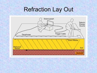
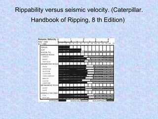
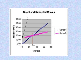
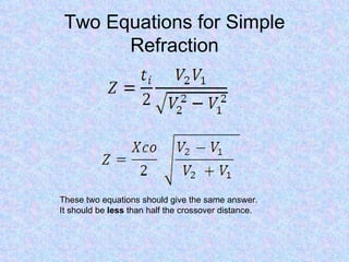
Seismic Refraction
Some uses of seismic refraction
• Mapping bedrock topography
• Determining the depth of gravel, sand or clay
  deposits
• Delineating perched water tables
• Determining the depth to the water table
• Detecting subsurface caverns
• Estimating rippability
• Detecting shallow faults and fracture zones
• Detecting large boulders
ACTIVE STANDARD: D5777-00(2006) Standard Guide
       for Using the Seismic Refraction Method for
                Subsurface Investigation
                                          $42.90 for PDF
•   Developed by Subcommittee: D18.01
    See Related Work by this Subcommittee
    Adoptions:
    Book of Standards Volume: 04.09

•   1. Scope

•   This guide covers the equipment, field procedures,
    and interpretation methods for the assessment of
    subsurface conditions using the seismic refraction
    method.
•   Seismic refraction measurements as described in
    this guide are applicable in mapping subsurface
    conditions for various uses including geologic,
    geotechnical, hydrologic, environmental, mineral
    exploration, petroleum exploration, and
    archaeological investigations.
•   The seismic refraction method is used to map
    geologic conditions including depth to bedrock, or
    to water table, stratigraphy, lithology, structure, and
    fractures or all of these.
•   The calculated seismic wave velocity is related to
    mechanical material properties. Therefore,
    characterization of the material (type of rock,
    degree of weathering, and rippability) is made on
    the basis of seismic velocity and other geologic
    information.
Refraction Lay Out
Seismic Refraction
• Advantages
  – Simple layout
  – Low manpower requirements
  – Limited Equipment Requirements
  – Rapid data reduction and analysis (computer
    not needed)
  – Easy interpretation
Seismic Refraction
• Disadvantages
  – Relatively large energy input required
  – Relatively long layout (10 times depth)
  – Limited number of model layers
  – Limited velocity differences
  – Limited interface geometry (assume smooth)
Rippability versus seismic velocity. (Caterpillar.
      Handbook of Ripping, 8 th Edition)
Direct Wave

              60.00
              50.00
miliseconds


              40.00
              30.00                                 0.00
              20.00
              10.00
               0.00
                      0   20       40     60   80
                                 Meters
Simple Plot
Distance   TimeD   Time R                             120
   0         0              30
                                                      100


                                 Time (miliseconds)
   6         8              32
                                                      80
  12        16              34
  18        24              36                        60
  24        32              38                        40
  30        40              40
                                                      20
  36        48              42
                                                       0
  42        56              44
                                                            0   20      40      60       80   100
  48        64              46
                                                                     Distance (meters)
  54        72              48
  60        80              50
  66        88              52
  72        96              54
  78        104             56
  84        112             58
Direct and Refracted Waves

              60.00
              50.00
miliseconds


              40.00
                                                       Series1
              30.00
                                                       Series2
              20.00
              10.00
               0.00
                      0      20     40     60   80
                                  meters
Two Equations for Simple
       Refraction


These two equations should give the same answer.
It should be less than half the crossover distance.
Steps in solving for depth
• 1 Determine the velocities of both layers
  in meters per second or feet per second
• 2 Determine the crossover distance
• 3 Determine the time intercept for V2
• 4 Determine the depth to layer 2 using
• Both refraction equations (internal check)
Down Dip   Up Dip
Dipping Bed Equations


   1  −1  v1         −1  v1   
γ = sin v      − sin 
                          v     
                                  
   2      2d             2u   


     1  −1  v1         −1  v1   
θ c = sin v      + sin 
                            v     
                                    
     2      2d             2u   

Refraction intro

  • 1.
  • 2.
    Some uses ofseismic refraction • Mapping bedrock topography • Determining the depth of gravel, sand or clay deposits • Delineating perched water tables • Determining the depth to the water table • Detecting subsurface caverns • Estimating rippability • Detecting shallow faults and fracture zones • Detecting large boulders
  • 3.
    ACTIVE STANDARD: D5777-00(2006)Standard Guide for Using the Seismic Refraction Method for Subsurface Investigation $42.90 for PDF • Developed by Subcommittee: D18.01 See Related Work by this Subcommittee Adoptions: Book of Standards Volume: 04.09 • 1. Scope • This guide covers the equipment, field procedures, and interpretation methods for the assessment of subsurface conditions using the seismic refraction method. • Seismic refraction measurements as described in this guide are applicable in mapping subsurface conditions for various uses including geologic, geotechnical, hydrologic, environmental, mineral exploration, petroleum exploration, and archaeological investigations. • The seismic refraction method is used to map geologic conditions including depth to bedrock, or to water table, stratigraphy, lithology, structure, and fractures or all of these. • The calculated seismic wave velocity is related to mechanical material properties. Therefore, characterization of the material (type of rock, degree of weathering, and rippability) is made on the basis of seismic velocity and other geologic information.
  • 4.
  • 5.
    Seismic Refraction • Advantages – Simple layout – Low manpower requirements – Limited Equipment Requirements – Rapid data reduction and analysis (computer not needed) – Easy interpretation
  • 6.
    Seismic Refraction • Disadvantages – Relatively large energy input required – Relatively long layout (10 times depth) – Limited number of model layers – Limited velocity differences – Limited interface geometry (assume smooth)
  • 7.
    Rippability versus seismicvelocity. (Caterpillar. Handbook of Ripping, 8 th Edition)
  • 9.
    Direct Wave 60.00 50.00 miliseconds 40.00 30.00 0.00 20.00 10.00 0.00 0 20 40 60 80 Meters
  • 10.
    Simple Plot Distance TimeD Time R 120 0 0 30 100 Time (miliseconds) 6 8 32 80 12 16 34 18 24 36 60 24 32 38 40 30 40 40 20 36 48 42 0 42 56 44 0 20 40 60 80 100 48 64 46 Distance (meters) 54 72 48 60 80 50 66 88 52 72 96 54 78 104 56 84 112 58
  • 11.
    Direct and RefractedWaves 60.00 50.00 miliseconds 40.00 Series1 30.00 Series2 20.00 10.00 0.00 0 20 40 60 80 meters
  • 13.
    Two Equations forSimple Refraction These two equations should give the same answer. It should be less than half the crossover distance.
  • 14.
    Steps in solvingfor depth • 1 Determine the velocities of both layers in meters per second or feet per second • 2 Determine the crossover distance • 3 Determine the time intercept for V2 • 4 Determine the depth to layer 2 using • Both refraction equations (internal check)
  • 18.
    Down Dip Up Dip
  • 21.
    Dipping Bed Equations 1  −1  v1  −1  v1  γ = sin v  − sin   v   2  2d   2u  1  −1  v1  −1  v1  θ c = sin v  + sin   v   2  2d   2u 