The document discusses the induced polarization (IP) method, including its origins, mechanisms, and measurement techniques. Specifically, it describes how:
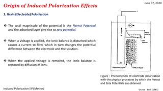
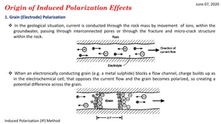
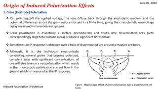
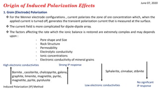
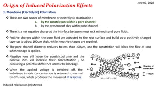
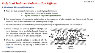
1) IP effects arise from either grain (electrode) polarization at mineral grain surfaces or membrane (electrolytic) polarization caused by pore constrictions or clays.
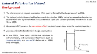
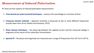
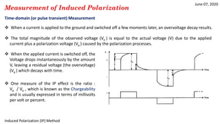
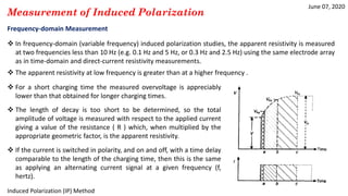
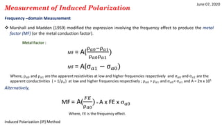
2) IP is measured using time-domain, frequency-domain, phase-domain, or spectral techniques to analyze the decay of voltage after an applied current is switched off.
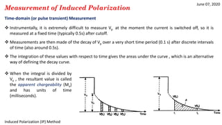
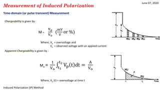
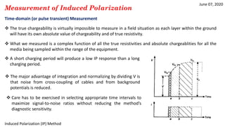
3) Time-domain techniques measure the decay curve of overvoltage over time after current switch-off to calculate chargeability and apparent chargeability.