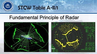
SlideShare a Scribd company logo
1 of 200
Download to read offline
Navigation V
STCW Table A-II/1
Learning Objectives
After completing this subject, the cadet will be able to:
Gain knowledge of the fundamentals of radar and automatic radar
plotting aids (ARPA)
Operate and interpret and analyze information obtained from radar
STCW Table A-II/1
STCW Table A-II/1
Specification of minimum standard of competence for officers
in charge of a navigational watch on ships of 500 gross
tonnage or more
STCW Table A-II/1
Function:
Navigation at the Operational Level
STCW Table A-II/1
Competence:
Use of radar and ARPA to maintain safety of navigation
STCW Table A-II/1
RADAR NAVIGATION
STCW Table A-II/1
What is RADAR?
The word radar is an abbreviation for Radio Detection
And Ranging
Radar is an electromagnetic systems used for detection
and location of objects such as aircraft, ship, vehicles,
people, natural environment etc.
The Use of Radar in Navigation
STCW Table A-II/1
Interpretation of the Radar Picture
The radar picture is a plain picture of the ships surroundings. Only
long training and experience can teach you to interpret the radar
picture quickly and accurately as well as to identify different targets.
Use of radar to assist in navigation can be divided into 3 categories:
Making Landfall
Coastal Navigation
Pilotage
STCW Table A-II/1
LANDFALL NAVIGATION
Landfall by radar may give surprises. Always remember: initial
radar fixes are often not reliable at long ranges and when
approaching land the picture may change completely.
STCW Table A-II/1
COASTAL NAVIGATION
Coastal navigation requires experience and vigilance all the time.
The range accuracy of the radar is generally better than the bearing
accuracy. When bearings has to be taken, choose isolated targets of
relative small size.
STCW Table A-II/1
PILOTAGE
For navigation in narrow waters, radar is great device. The
navigator must know radar shadows. Knowledge is essential in order
to distinguish clearly between stationary and moving objects.
STCW Table A-II/1
STCW Table A-II/1
Fundamental Principle of Radar
Transmitter generates and transmits electromagnetic wave (sine or pulse).
A portion of it is reflected back by the target (object you want to identify).
The radiated portion is collected by the radar antenna and processed.
One antenna can be used for both transmission and reception
STCW Table A-II/1
RADAR- derived from the phrase RADIO DETECTION AND RANGING.
A short burst of electro magnetic energy transmitted and hit to an
object and then return, since the velocity of the propagation is known
it would be easy to calculate because the distance to the object as
long as it can measure time from which the transmission started until
the echo return.
STCW Table A-II/1
Fundamental Principle of Radar
On Board Ship the RADAR has two main tasks:
➢To function as an aid to prevent collision, as with the help of
RADAR one can “SEE” in fog and darkness.
➢To assist in navigation, particularly at landfalls and when
navigating in coastal waters.
STCW Table A-II/1
Fundamental Principle of Radar
STCW Table A-II/1
Characteristics of Radar Sets and Factors
Affecting Performances
STCW Table A-II/1
RADIO WAVES are Electro magnetic Waves motion consist of crest and
trough.
STCW Table A-II/1
Wavelength- is a distance between a successive crest of waves,
electromagnetic waves of a length between 0.1-30000 mm are known as
radio waves.
Frequency- are other way of measure of waves motion, which indicates
the number of crest that pass a fix of initial time.
Frequency and Wavelength are two terms closely associated.
STCW Table A-II/1
LOW FREQUENCY VS HIGH FREQUENCY
Each type has their advantages and disadvantages. For example a short
wave length is preferred in shipboard radar system because there Is a
relationship between the size of the antenna and the Horizontal Beam
width, the larger width of the scanner the smaller is the angular beam
width for the same wavelength.
STCW Table A-II/1
LOW FREQUENCY HIGH FREQUENCY
Most marine radar transmit is:
X Band (3 cm) - 9000 MHZ
C Band (5 cm) - 5000 MHZ
S Band (10 cm) - 3000 MHZ
STCW Table A-II/1
Marine Radar Component
STCW Table A-II/1
ANTENNA
TRANSCEIVER TRANSMITTER
MAGNETRON
MODULATOR
TRIGGER
POWER
TRANSFORMER
DISPLAY
RECEIVER
MIXER
1ST AMPLIFIER
EQUALIZER
VIDEO AMPLIFIER
RADAR BLOCK DIAGRAM
STCW Table A-II/1
RADAR ANTENNA
Transmit and receive in an concentrated beam and a motor turns
the antenna in rotation, the signal, which are amplified the signal
becomes visible to the operator in form of a radar picture.
STCW Table A-II/1
Two types of RADAR ANTENNA:
SLOTTED WAVE GUIDE
TYPE
STCW Table A-II/1
Two types of RADAR ANTENNA:
PARABOLIC TYPE
STCW Table A-II/1
RECEIVER
The incoming signal is fed to a series of amplifier and further to detect or
demodulator for which smoothen the signal, the main task of the receiver is
to amplify the reflected (incoming echoes) weak echoes and make them
suitable for transmission to the indicator.
STCW Table A-II/1
TRANSMITTER
It is the trigger pulses to the modulator and converted the inputs into
a high frequency oscillation thru magnetron. A high frequency
oscillation are fed via wave guide or into a coaxial cable to the
transmitter/receiver switch.
STCW Table A-II/1
DISPLAY
A radar echoes are display in a cathode ray tube (CRT). Several types
of CRT are utilized like A-SCAN or Short Persistent Tube, Plan Position
Indicator or PPI, Raster Scan Display.
A-SCAN or short persistent tube, the strength of an echo derived from
its amplitude.
STCW Table A-II/1
DISPLAY
PPI is a long persistent tube, the trace is rotated around in unison
with the rotation of the scanner and echoes previously recorded are
retained during a period of at least one scanner revolution.
STCW Table A-II/1
P.P.I DISPLAY
STCW Table A-II/1
DISPLAY
RASTER SCAN DISPLAY. Normally a rectangular screen with dimension in the
ratio 4:3 consisting of; example 1024 horizontal lines and 1280 vertical line
or picture elements (pixel)
The radar provides all echoes information in Cartesian form (i.e. range,
bearing). Before the information can be displayed the information must be
recalculated into X-Y coordinated by a processor.
STCW Table A-II/1
RASTER SCAN DISPLAY
STCW Table A-II/1
DISPLAY
The advantage of raster scan is that, it can be viewed in daylight
without a visor, and the capacity for the additional graphic information
is almost unlimited compared with the PPI.
The disadvantage of the raster scan is that even the best raster scan
display available today, cannot match the resolution of the old PPI.
STCW Table A-II/1
Factors External to the Radar Set Affecting
Detection
STCW Table A-II/1
RADAR SCAN & RADAR SWEEP
Radar Scan- it is a one complete 360 degrees rotation of the antenna
(during one scan normally thousand sweeps are generated and
transmitted)
Radar Sweep- is the transmission of one radar pulse only.
STCW Table A-II/1
PULSE REPETITION FREQUENCY (PRF)
Define as the number of pulses transmitted per second.
Long pulse is equals to low PRF
Short pulse equals to high PRF
LONG PULSE- means more power and longer range but less resolution
in range.
SHORT PULSE- means a weaker pulse, less radar range but better
resolution in range.
STCW Table A-II/1
RADAR RANGE DEPEND MAINLY IN DIFFERENT PARAMETERS
Vertical Beam Width
Selected Pulse Length
Height of Antenna
Installation of Antenna
Ship’s Trim
STCW Table A-II/1
Safe Distance
STCW Table A-II/1
IMPORTANT RADAR RANGE PARAMETERS
Antenna Height
Height of the Target
Size of the Target
Target Reflecting Area
Materials of the Target
Shape of the Target
Weather Condition
STCW Table A-II/1
FOLLOWING PARAMETERS MUST BE TAKEN INTO ACCOUNT:
Transmitted Peak Power
Wavelength
Pulse Length
Antenna Gain
Noise Figure
Number of Pulses Per Scan
Wave Guide Loss
Display Parameters
STCW Table A-II/1
RANGE DISCRIMINATION
The ability of radar to discriminate between two small
object close together in the same bearing.
Effecting range discrimination are:
Select Pulse Length
The size of the spot
If possible short pulse and short range should be selected and
focused, brightness carefully adjusted.
STCW Table A-II/1
BEARING DISCRIMINATION
The ability of radar to discriminate between two small
object close together at the same range but different
bearing.
Bearing discrimination depends on:
Horizontal Beam Width
The spot size
Correct focusing and brightness setting will improve the
bearing discrimination.
STCW Table A-II/1
BEARING AND RANGE DISTORTION
The radar’s possibility to reproduce on area or a ship correctly
and to discriminate between close lying targets is limited and
varies with different types of radar.
The discriminating ability in range is usually 25-75 meters,
however the accuracy is lower on long range.
STCW Table A-II/1
BEARING AND RANGE DISTORTION
The discriminating ability laterally is usually 1-2 degrees.
Radar sets with a wavelength of 3 cm have a better
discriminating ability compared with the 1 cm wavelength.
STCW Table A-II/1
Radiation Hazards and
Precaution
STCW Table A-II/1
MAGNETIC COMPASS
The magnetic compass must have a safe distance from the radar.
Nowadays, although most ships are equipped with zero compass,
the magnetic compass is still the master compass on all ships and
thus should be taken good care of.
Normally the safe distance varies between 1 and 5 meters.
STCW Table A-II/1
RADIATION
Marine radar transmits energy of varying strength in form of short pulses or
bursts. Pulse power can produce biological changes not obtained with
constant wave transmission. At short distance, transmission from marine
radars may pose a health hazard, follow the instruction from the radar
manufacturer closely and don’t take any chances.
STCW Table A-II/1
RADIATION
When working close to a radar antenna, make sure that a warning
signal has been placed on the radar console. Clearly telling
everybody that no start up should be attempted before the work on
the antenna is completed or cancelled.
STCW Table A-II/1
RADIATION
Whenever the air humidity is abnormally high which it is in fog, rain,
snow and hale, a reduction in radar detection range should be
expected.
Some disturbances of radar picture:
Sea
Rain
These disturbances maybe serious so refer to the radar manual for
more details.
STCW Table A-II/1
NORMAL TRANSMISSION OF RADAR WAVES
Radar conditions at approximately 10-15% greater that the distance
to the optical horizon said to have normal transmission of radar
waves.
Generally, normal conditions exist in areas with cold air masses. The
longer the wavelength, the greater is the tendency to bend round
objects.
STCW Table A-II/1
SUB-REFRACTION
When warm, moist air remains over cold water, the air is cooled from
below creating a fog. Temperature end humidity will increase with
altitude and the radar wave will bend upwards; decreasing the radar
range is called sub-refraction.
STCW Table A-II/1
DUCTING
With conditions of light wind and low clouds over cold water we
often get a condition called “ducting”. That is, when radar beam is
reflected several times between the fog and sea surface. The radar
range can be increased considerably.
Ducting can be expected to take place when temperature inversion
exist and the atmosphere is calm.
STCW Table A-II/1
RADAR BLACKOUT
With conditions of considerable ground fog, we can get a total radar
blackout:
All radar waves are reflected from the top of the fog.
Stationary warm air masses located on top of cold sea.
If the height of the fog is less that the height of the radar antenna, a total
reflection of the radar signal from the top of the fog may take place.
STCW Table A-II/1
SEA CLUTTER
Sea clutter echoes are caused by reflection of the radar pulse against the
sea waves. The reflection is specular and conditions for the pulse to return
to the scanner are favorable near the ship. At longer ranges the beam will
be deflected away from the ship.
Marine radars are equipped with rejection systems to minimize the effect
of sea clutter. This control is often named “Anti Clutter Sea” or “STC”.
STCW Table A-II/1
RADAR SHADOW
As we have seen, the radar waves transmit in a straight line. A radar
coastline echo (or any other objects) appearance will be determined by the
topography.
Another important reason for the difference between sea map and the
radar image is the radar range and bearing discrimination parameters, i.e.
how much the radar “magnifies” the echo in range and bearing.
STCW Table A-II/1
CENTERING ERRORS
The sweep center, which on the PPI indicates own ship, must coincide
exactly with the cursor center of rotation to achieve a correct bearing.
Another important reason for the difference between sea map and the
radar image is the radar range and bearing discrimination parameters, i.e.
how much the radar “magnifies” the echo in range and bearing.
STCW Table A-II/1
RADAR REFLECTORS
The purpose of radar reflector is to direct as much as possible of the
reflected radar energy back to the radar antenna, which means
stronger echoes on the PPI.
RADAR BEACONS
Racon signal appears in PPI and provides bearing and range of target.
STCW Table A-II/1
THREE MOTION COMPONENTS
The targets relative course and speed is the targets motion in
relation to own ship during the echoes movements across the PPI on
a relative motion display.
The targets true course and speed is the targets true motion during
the period of observation.
The own ships course and speed are your ships true motion during
the period of observation.
STCW Table A-II/1
MULTIPLE ECHOES
Multiple echoes can be created by reflection between own ship and an
object before the scanner finally collects its energy. We will see a line of
targets on the same bearing and with equal distance between them.
True echo is the one closest to own ship. The shapes of multiple echoes
are less defined that that of the original echo and they are weakening in
intensity outwards.
STCW Table A-II/1
SIDE ECHOES
The side lobes cause side echoes. The effect of side echoes will only
be observed at short ranges. Nearby target are picked up by the side
lobes as well as by the main lobe. Anti sea clutter will normally
remove side echoes.
STCW Table A-II/1
BLIND SECTORS
Antenna not placed at the ships highest point. Structures above antenna will
create blind sector in radar screen. Objects within these sectors will normally
be invisible in the screen.
The blind sectors can be seen as distinctly dark sectors in the sea clutter area.
Plot each sector on a plotting sheet and place this so it can easily be seen from
the radar observed position.
STCW Table A-II/1
HEADING MARKER ERRORS
When the heading marker on the radar screen does not exactly tally with
the ships heading, or in other words, when the echo from a target
straight ahead does not lie exactly on the heading line, then we have a
heading marker error.
Heading Marker error may have serious effects on the radar picture and
has been the cause of many collisions.
STCW Table A-II/1
FALSE ECHOES
If the radar signal is reflected from objects on board in such a way
that the pulse hits a target, we may receive a false echo at almost the
same distance as to the real target but on a different bearing.
The navigator should know exactly where own ships blinds sectors
are located. This is important in order to take actions to minimize the
effect of the blind sectors.
STCW Table A-II/1
RAIN SQUALLS AND SHOWERS
Rainsqualls and showers appear on the screen as a wooly mass.
An intense rainstorm can be detected up to 25 miles
Thunderstorms give excellent echoes
Rain and clutter and targets beyond the rain area will obscure
echoes inside the rainstorm
STCW Table A-II/1
WEATHER CONDITION
During weather conditions including heavy rain, thunderstorms etc.,
the S-band is a better choice than X-band radar.
False echoes and disturbances
Own ships antenna receives signals from another radar
Fan shaped broken lines emanating from the center of the screen
Most radar equipments contain radar interference rejection circuits
to eliminate this disturbance
STCW Table A-II/1
SYMBOLS FOR RADAR CONTROL
1. Radar Off
2. Radar On
3. Radar Stand By
4. Aerial Rotating
5. North-up Presentation
6. Head-up Presentation
7. Heading Marker Alignment
8. Range Selector
9. Short Pulse
10. Long Pulse
11. Gain
SYMBOLS FOR RADAR CONTROL
12. Tuning
13. Anti Clutter Rain Minimum
14. Anti Clutter Rain Maximum
15. Anti Clutter Sea Minimum
16. Anti Clutter Sea Maximum
17. Scale Illumination
18. Display Brilliance
19. Range Rings Brilliance
20. Variable Range Marker
21. Bearing Marker
22. Transmitted Power Monitor
STCW Table A-II/1
SYMBOLS FOR RADAR CONTROL
STCW Table A-II/1
SYMBOLS FOR RADAR CONTROL
There are seven main controls that determine the performance
of the radar:
standby/transmit
brilliance
gain
tuning
range
anti sea clutter control (STC)
anti rain clutter control (FTC)
STCW Table A-II/1
Symbols For Radar Control
STCW Table A-II/1
Standby/Transmit
The standby/transmit switch usually has three positions labelled ‘off’,
‘standby’, and ‘transmit’. Turning the switch to standby will activate the
radar set, however it doesn’t come on immediately as the magnetron
needs a few minutes to warm up before it can transmit. The radar will
have some form of visual signal to indicate when this period is expired.
STCW Table A-II/1
Standby/Transmit
The radar can then be switched to ‘transmit’ and on some sets a short or
long pulse can be selected at this time, normally long pulse would be
selected. A long pulse will be more likely to show an echo from a weak
target or a target at a longer range. A short pulse will achieve better
definition on short ranges.
STCW Table A-II/1
Standby/Transmit
As well as its main function of giving the magnetron time to warm up, in
‘standby’ mode the scanner is not rotating (on most sets) and is a way of
conserving power and prolonging the life of the magnetron while keeping
the set ready for immediate use.
STCW Table A-II/1
Brilliance
The brilliance control on an analogue radar controls the brightness of
the rotating trace and will also affects the brightness of the displayed
echo so it needs to be adjusted so that the trace itself is just visible, to
give a good contrast between echo and background.
On a raster scan display the brilliance control regulates the brightness of
the picture, making it bright enough for daylight viewing or dim enough
so as not to impair the operators night vision.
STCW Table A-II/1
Gain
The gain control may appear to have a similar function as the brilliance
control in that operating it makes the picture brighter or darker. This
similarity however, is only superficial as the gain control has a
completely separate function and it is important not to confuse the
two.
The gain control affects the receiver and not the display as the
brilliance does.
STCW Table A-II/1
Tuning
The tuning control can be compared to the tuning control of an
ordinary radio, in that it tunes the receiver to the frequency of the
transmitter. Poor tuning adjustment may not be easily recognised on
the screen. Tuning slightly out will eliminate some very weak echoes,
but still produce a clear picture of the stronger ones. Hence the
importance of frequent fine tuning of the set.
STCW Table A-II/1
Range
The range control regulates the range at which the set operates. It
simply changes the size of the area on the display and hence the scale.
You would change the range of the radar just as you would change
charts for passage planning or close-in piloting. The choice of range
would depend on what you are using the radar for, and your locality.
STCW Table A-II/1
Sea Clutter Control (STC)
The radar beam will bounce echoes off the sea around the ship,
particularly if the weather is a little rough. This result will be a bright
sunburst pattern in the middle of the screen which will be more
pronounced in the upwind direction. You could reduce this by turning
down the gain, the down side to that solution however, is that the
echoes of more distant targets will be lost as well.
STCW Table A-II/1
Rain Clutter Control (RTC)
The rain clutter control will reduce the interference on the screen due
to the rain and increase the chance of seeing targets within rain
showers. The effect on returning echoes from rain on the screen is
usually no more than a transparent smear, looking a little like cotton
wool, but it can be dense enough to conceal other echoes within the
shower.
STCW Table A-II/1
Rain Clutter Control (RTC)
The rain clutter control works by making use of the fact that the
returning echo from rain is different from the returning echo of a solid
object. The returning echo from rain is much longer and very much less
dense than the echo from a solid object. The rain clutter circuitry works
by passing on to the receiver only the leading edge of a returning echo.
STCW Table A-II/1
Setting Up Radar Display
STCW Table A-II/1
START UP SEQUENCE
Radar ON/OFF
Radar Standby
Scanner ON/OFF
STCW Table A-II/1
CHOICE OF RADAR PRESENTATION
Many factors may influence a navigator’s choice of radar presentation.
Availability of equipment and own experience will naturally be deciding
factors, but it is important that navigator is aware that he is not completely
free in his selection of radar presentations.
A navigator on a ship equipped with True Motion Radar, operating in an area
with dense traffic is obliged to utilize True Motion radar presentation in order
to avoid additional problems in a possible collision case.
STCW Table A-II/1
MEASUREMENT OF RANGE
The range accuracy of radar is generally high. Range can be measured
on radar with reference to fixed range rings equally spaced around own
ships position on the radar screen
The Variable range ring should regularly be checked for accuracy against
the fixed range rings, which are normally most stable. With a variable
range ring more accurate measurements can be taken
STCW Table A-II/1
BEARING ACCURACY
The bearing accuracy of massive radars is normally not so high
Beam with distortion, which can be partly eliminated by reduction in gain.
Heading marker error, which can be determined by various methods
Centering error, which can easily be corrected
Error due to yawing of own ship
Error due to parallax when viewing the display
Always read and follow the radar manufacturer recommendations for use and
maintenance of the radar equipment. This will save you time and money and ensure
proper use of equipment.
STCW Table A-II/1
PLOTTING
Purpose of Plotting
It can show whether danger of collision exists, how close will pass the
target and how much time there is left before this will take place.
Approximate determination of the course and speed of the other vessel,
so that sensible avoiding action can be taken when needed.
Manual plotting in connection to radar means to mark one or more
echoes within a specific time interval and thus decide the target’s
movement in relation to own ship.
The objective of plotting is to obtain the clearest possible picture of the
situation.
STCW Table A-II/1
The Plotting Process
Detection- recognition of the presence of the target.
Selection- choosing of target requiring closer observation
Tracking- the process of observing changes in target position
Plotting- the whole process of detection, selection, tracking, calculation
of targets parameter
STCW Table A-II/1
Target Aspect
The aspect is defined as the angle of view however, in connection
with plotting we will use the term “Calculated Aspect” in order to
distinguish between the two.
It can be defined as the angle between the target ships heading and
bearing to own ship, as seen from the target ship.
In connection with plotting and use of radar and ARPA, we had
better define what we receive from these systems as calculated
aspect.
STCW Table A-II/1
Target Aspect
Target Ship
Aspect Red 40
Own Ship
Aspect B measured from dead to a head to 180
degrees on either side of the ship.
STCW Table A-II/1
Relative Aspect
Relative speed is defined as the target speed relative to own ship, as
deducted from a number of measurements of its range and bearing on
the radar, expressed as an angular distance from own ships heading.
STCW Table A-II/1
Plotting Triangle
Knowledge of the speed triangle is essential for
understanding the principles used in plotting.
R
E
M
R - M = Echo Line/Relative Track
E – M = Target Ship Course and Speed
E – R = Own Ship Course and Speed
STCW Table A-II/1
Heading
Defined as the direction in which the bow of a vessel is pointing,
expressed as an angular distance from north.
North
Heading 45
45 degrees
STCW Table A-II/1
Relative Bearing
If the relative bearing of an approaching target remains the same over
time, collision danger is observed.
Relative Bearing
of Target 030 degrees
Own Ship Heading
STCW Table A-II/1
True Bearing
On merchant ships, true bearing is mainly used for
position fixing.
North
True Bearing 300 degrees
STCW Table A-II/1
Bearing
On a ship bearing can be relative or true in connection with traffic
surveillance, relative bearing are often used.
True North
Relative Bearing
Ship’s Heading
015 degrees
Relative Bearing
STCW Table A-II/1
CPA (Closest Point on Approach)
CPA must not be mixed with the point where the target crosses own ship’s
heading, often referred to as BCP (Bow Crossing Point)
Bow Crossing Point
CPA
TCPA
STCW Table A-II/1
TCPA (Time Closest Point on Approach)
TCPA is the time estimated as measured along the echo line form its
present position to the closest point on approach.
Bow Crossing Point
CPA
TCPA
STCW Table A-II/1
Maneuvering Board
Plotting can be done with head up or north up however, regardless of
selected radar presentation it is advantageous to plot with north up.
True Plotting
Gives a natural and easily understood picture of the course of events.
Can be done directly in the chart if the scale is large enough to give a
clear picture.
Gives an easily understood picture of the situation
STCW Table A-II/1
Relative Plotting
Own ship is considered a fixed point. Plotting must be done with high
accuracy and great care.
Heavy traffic can make manual plotting impossible.
STCW Table A-II/1
Electronic Plotting
Today many modern radars are equipped with an electronic plotting
feature. Used together with EBL (Electronic Bearing Lines) is very good
tool in the hands of a qualified navigator. These radar features make
plotting direct on the radar display very convenient and replace the
need for reflection plotter or plotting sheets.
STCW Table A-II/1
Errors in Manual Plotting
Even small errors in one or several of these parameters can cause large
and dangerous errors in the plot calculations. Always check these
parameters as thoroughly as possible in order to reduce the
possibilities for “nasty surprises” during manual plotting work.
STCW Table A-II/1
Sources of Errors in Manual Plotting
Bearing Error
Distance Error
Error in timing between plots
Error in speed
Gyro Error
Relative Speed
Maneuvering of own vessel
Unstable steering, yawing, etc.
STCW Table A-II/1
Errors in Manual Plotting
STCW Table A-II/1
Collision Danger
The usual method of deciding whether a collision danger is present is
taking several bearings. This is time consuming, and it requires that
many bearings have to be taken.
A dangerous situation can quickly emerged by taking a few inaccurate
bearings from a comparatively long distance and then “forgetting” the
target if the CPA is considered large enough.
STCW Table A-II/1
Errors in Distance Measurement
An error in distance measurement, as in bearing error, can produce
grave results when judging the traffic situation.
Errors in Timing
A timing error between two plots will result in calculation of incorrect
target course, speed and time to CPA.
STCW Table A-II/1
Errors in Speed
An error on speed causes incorrect calculation in the same manner as
error timing. However, we must remember that in all plotting where we
wish a picture of aspect, own vessels speed through the water must be
utilized. Never make corrections due to current or drift. In connection
with plotting, speed through water should be used.
STCW Table A-II/1
Gyro Error
Make it a habit to always correct the gyro for known gyro error
target with low speed.
Factors That Affects Manual Plotting
Unstable Steering
Maneuvering of Own Ship
The Technical Exactness of the Equipment
Rough Weather Conditions
Target Relative Speed
The Navigator’s Experience and Lack of Plotting Practice
STCW Table A-II/1
Relative Radar Plotting Symbols
STCW Table A-II/1
Symbols are signs, letters, or abbreviations used to replace words.
They are used in mathematics and certain sciences to good advantage
by reducing the amount of space required explaining a thing. Since
symbols take the place of words and, they form a language of their
own her here is a list that is used in Radar Plotting.
STCW Table A-II/1
STCW Table A-II/1
RADAR PLOTTING
SYMBOLS AND MEANING
CPA - Closest Point of Approach.
DRM - Direction of relative movement
e - point of origin of the own ship
e-m - Contact's vector
e-r - Own ship's initial vector
e-r' - Own ship's final
OC - Own ship's initial course.
m - The head of the relative motion vector (r-m) also the head of the contact's
vector (e-m).
STCW Table A-II/1
RML - Relative Motion Line.
SRM - Speed of Relative Movement.
TCPA- time closest point of approach
NCPA- new closest point of approach
ST- actual target’s true speed
CT- true course of target
mx- point of execution
AC- collision avoidance course
AS- collision avoidance speed
ROCS- resume ownership course and speed
STCW Table A-II/1
NRML - New Relative Motion Line the Relative Motion Line after
own ship has maneuvered.
r - The head of own ship vector (e-r).
r-m - The relative motion vector.
M1 - First plotted position of contact
STCW Table A-II/1
ARPA System
STCW Table A-II/1
What is ARPA?
An abbreviation for Automatic Radar Plotting Aids. Basically an ARPA is
a computerized radar plotting system, which can perform radar plotting
manually or automatically according to operator’s choice.
When it works properly, ARPA is a fantastic tool in the hands of a
qualified navigator with proper training.
STCW Table A-II/1
What is ARPA?
An ARPA assesses the risk of collision, and enables operator to see
proposed maneuvers by own ship. While many different models of ARPAs
are available on the market, the following functions are usually provided:
1. True or relative motion radar presentation.
2. Automatic acquisition of targets plus manual acquisition.
STCW Table A-II/1
3. Digital read-out of acquired targets which provides course, speed,
range, bearing, closest point of approach (CPA, and time to CPA
(TCPA).
4. The ability to display collision assessment information directly on the
PPI, using vectors (true or relative) or a graphical Predicted Area of
Danger (PAD) display.
STCW Table A-II/1
What is ARPA?
5. The ability to perform trial maneuvers, including course changes, speed
changes, and combined course/speed changes.
6. Automatic ground stabilization for navigation purposes. ARPA processes
radar information much more rapidly than conventional radar but is still
subject to the same limitations. ARPA data is only as accurate as the data
that comes from inputs such as the gyro and speed log.
STCW Table A-II/1
Types of ARPA
In the early days, ARPAs of broad categories existed and were generally
referred to as “stand alone” and “integral”
a) Stand-alone ARPA
These were primarily intended as additions to conventional radars.
They provided all of the ARPA facilities but derived their data from
“host” radar.
STCW Table A-II/1
a) Stand-alone ARPA
Stand-alone equipment had to be interfaced to a variety of existing
equipment and while it was the less expensive and more expedient
of the two alternative, it was never the solution and so, today,
most of the ARPA’s being fitted into the “integral” category.
Stand-alone ARPA works in two ways; The radar system receives all the
raw data and transmits all these data to ARPA for processing.
STCW Table A-II/1
b) Integral ARPA
In the modern integral ARPAs, a computer, usually referred to as the
processor, is incorporated in the radar/ARPA system so that the ARPA
data can be displayed on the same screen as the conventional radar
data.
STCW Table A-II/1
How ARPA is used?
STCW Table A-II/1
The ARPA is connected to the radar from which it automatically
extracts data, processes it and displays it along with graphics and
possibly alphanumeric. A computer forms the heart of the system
which plots the targets and displays the vector associated with each
tracked target.
How ARPA is used?
Having first set up the ARPA display (as normal radar display), select:
a) Range scale- e.g 12 miles
b) Plot- Relative (true) bearings
c) Mode- North-up (head-up or course up)
d) Mark the targets to be tracked (using joystick and gate)
e) Set the “vector length”--- in minutes
f) Check the course and speed input
STCW Table A-II/1
STCW Table A-II/1
ARPA
INFORMATION
DISPLAY
General Features
Daylight-bright high-resolution display
28 inch diagonal CRT presents radar picture of 360 mm effective
diameter with alphanumeric data area around it
User friendly operation by combination of tactile backlit touch pads, a
trackball and rotary controls
STCW Table A-II/1
General Features
Audio-visual alert for targets in guard zone
Echo trail to assess targets’ speed and course by simulated afterglow
Electronic plotting of up to 10 targets in different symbols (This function
is disabled when ARPA is activated)
STCW Table A-II/1
General Features
Electronic parallel index lines
Interswitch (optional) built in radar or ARPA display unit
Enhanced visual target detection by Echo Average, Echo Stretch,
Interference Rejector, and multi-level quantization
STCW Table A-II/1
General Features
Stylish display
Choice of 10, 25 or 50 KW output for X-band; 30 KW output for S-band,
either in the transceiver aloft (gearbox) or RF down (transceiver in
bridge)
Exclusive FURUNO MIC low noise receiver
STCW Table A-II/1
ARPA Features
Acquires up to 20 targets automatically
Movement of tracked targets shown by true or relative vectors (Vector
length 1 to 99 min. selected in 1 min steps)
Setting of navigation lines, buoy marks and other symbols to enhance
navigation safety
STCW Table A-II/1
ARPA Features
On-screen digital readouts of range, bearing, course, speed, CPA, TCPA,
BCR (Bow Crossing Range) and BCT (Bow Crossing Time) of two targets
out of all tracked targets.
Audible and visual alarms against threatening targets coming into
operator-selected CPA/TCPA limits, lost targets, two guard rings, visual
alarm against system failure and target full situation
STCW Table A-II/1
STCW Table A-II/1
ARPA Main Control Panel
DISPLAY CONTROLS - MODE PANEL
STCW Table A-II/1
DISPLAY CONTROLS - MODE PANEL
HM OFF- Temporarily erases the heading marker.
ECHO TRAILS- Shows trails of target echoes in the form of simulated
afterglow.
MODE- Selects presentation modes: Head-up, Head-up/TB, North-up,
Course-up, and True Motion.
STCW Table A-II/1
DISPLAY CONTROLS - MODE PANEL
GUARD ALARM- Used for setting the guard alarm.
EBL OFFSET- Activates and deactivates off-centering of the sweep
origin.
BKGR COLOR- Selects the background color.
INDEX LINES- Alternately shows and erases parallel index lines.
STCW Table A-II/1
DISPLAY CONTROLS - MODE PANEL
X2 ZOOM- enlarges a user selected portion of picture twice as large
as normal. (R-type only)
CU, TM RESET- Resets the heading line to 000 in course-up mode;
moves own ship position 50% radius in stern direction in the true
motion mode.
INT REJECT- Reduces mutual radar interference
RANGE RINGS- Adjusts the brightness of range rings.
STCW Table A-II/1
How is numerical data relating to a particular target found?
By using the joystick and placing the gate marker ring over a particular
target, data in numerical form relating to that target can be obtained:
a. range and bearing
b. course and speed
c. CPA and TCPA
This data may be made to appear sequentially simultaneously on a
special data display. Alternatively, alpha-numeric may be used to make
the data appear on the display, alongside the particular target.
STCW Table A-II/1
What extra facilities are available in the ARPA system?
1.Trial Maneuver
It should be possible to simulate the effect to a maneuver-- “own ship”-
o- on all tracked targets. This is done by the feeding in:
a)the propose course
b)the proposed speed
c)the delay(if any)
STCW Table A-II/1
What extra facilities are available in the ARPA system?
2.Operational Warning
a)CPA warnings- it is possible to set limit of CPA and TCPA which if
violated by a tracked target, whether its vector actually reaches the
warning area or not, will activate an alarm. The offending target will be
by a brighter than normal or flashing vector or a special symbol.
STCW Table A-II/1
What extra facilities are available in the ARPA system?
2.Operational Warning
b)Guard rings and zones- it should also be possible to warn the
observer if any distinguishable target closes to a range or transits a
zone chosen by the observer. The first appear will not activate the
alarm. The existence of guard rings should not be regarded as an
alternative to keeping a proper lookout.
STCW Table A-II/1
What extra facilities are available in the ARPA system?
2.Operational Warning
c)Target lost- the ARPA should clearly indicate if a target is lost with the
last tracked position being clearly indicated.
STCW Table A-II/1
Methods of Displaying Information
Since the first computerized radar system came on the market and to this
very day many different ways of presenting the information has been
developed, produced and delivered. Today, regardless of graphic
presentation, all ARPA systems must be able to present target
information in form of both relative and true vectors.
STCW Table A-II/1
Methods of Displaying Information
Both time of vectors should be time adjustable. In addition to displaying
target information graphically, all ARPA’s also display target information
digitally on the traffic display or on a separate screen.
In additional a number of graphical symbols are used for different
purposes:
Defining stationary targets
Indicating navigational marks
Sailing routes
Pointing out targets that cause alarms etc.
STCW Table A-II/1
Symbols and Definition
TV - True Speed Vector indicates the targets speed and course.
STCW Table A-II/1
Symbols and Definition
RV - Relative Speed Vector indicates target relative course and speed.
STCW Table A-II/1
Symbols and Definition
TH - Track History should be provided on request, consisting of at least four equally
spaced past positions of the echo.
STCW Table A-II/1
Symbols and Definition
PPC - POINT OF POSSIBLE COLLISION is the point at which a collision could take place.
STCW Table A-II/1
Symbols and Definition
PAD - Predicted Area Of Danger is the area to be avoided based on CPA and TCPA
setting and relative target speed.
STCW Table A-II/1
Area Rejection Boundaries (ARBs, AEBs)
It is possible to place electronic lines on the screen which eliminate
automatic plotting in selected areas. The lines are adjusted for
“rotation” and “transaction” controls. These reduced the load on the
tracker when in the proximity to a coast echo.
Alternative systems provide automatic acquisition in zones which may
be designated by range and sector controls.
STCW Table A-II/1
Equipment Fault in ARPA system
a.Connection with other equipment
The connection of the ARPA to any other equipment should not
downgrade the performance of that equipment. The failure of an input
from other equipment, such as log or compass, should activate an alarm.
STCW Table A-II/1
Equipment Fault in ARPA system
b.Performance tests and warnings
Self diagnosis should activate a warning in the event of ARPA malfunction.
Also means shall be available to check the correct interpretation of data
against a known solution.
STCW Table A-II/1
What alternatives facilities are available on ARPA system?
a.Automatic Acquisition
It is permissible for targets to automatically, as well as manually
acquired. But where automatic acquisition is provided, the operator
must be able to select the areas in which it operates.
STCW Table A-II/1
What alternatives facilities are available on ARPA system?
b.Manual Acquisition
The operator specifies the target to be subsequently tracked. To do this,
a joystick and screen marker or tracker ball and screen marker are used.
The target is entered into or removed from the computer memory when
the acquire or cancel button is press.
STCW Table A-II/1
What alternatives facilities are available on ARPA system?
c.Tracking and Acquisition Limits
There will may be times when targets are close to own ship but present no
real threat, and whose vectors may well clutter up the center of the display.
It may be possible therefore to set limits on the ranges at which targets are
acquired and to which they are tracked.
STCW Table A-II/1
What alternatives facilities are available on ARPA system?
d.Potential Points of Collision (PPCs)
From the basic plot of a target, it is possible to determine the course to
steer in order a collision or interception will take place. It is possible to
have these PPCs appear on the display and in this way, allow the
navigator to avoid them.
STCW Table A-II/1
What alternatives facilities are available on ARPA system?
e.Predicted Areas of Danger (PAD)
It is logical step from PPCs to indicate areas around these points
into which vessel should not do in order to ensure that some
specified clearing range is maintained.
STCW Table A-II/1
What alternatives facilities are available on ARPA system?
f.Methods of Testing an ARPA for malfunction
These usually take the form of self-diagnostic routines with some
indicator of the unit or Printed Circuit Board which is found to be faulty.
STCW Table A-II/1
What alternatives facilities are available on ARPA system?
g.ARPA facilities
Finally the first true ARPA appeared, a system able to extract the signal
from the targets then pass them to a digital processor. Once the data is
within the processor of these equipment, a variety of facilities will
present information to the observer.
STCW Table A-II/1
What alternatives facilities are available on ARPA system?
These facilities includes:
1.Relative Vectors 6. Trial Maneuver
2.True Vectors Output 7. Digital Data
3.Points of Collision 8. Navigational Lines and Limits
4.Predicted Areas of Warning 9. Operational Danger
5.History of Warning 10. Equipment
11. Rejection Boundaries
STCW Table A-II/1
This section gives you information about IMO requirements for ARPA
system including performance standard for gyro and log.
Performance Standards for Automatic Radar Plotting
Aids (ARPA) Resolution A.422 (XII)
STCW Table A-II/1
Theory of ARPA Tracking System
STCW Table A-II/1
Explains processing delay and other important limitations in the
system. When operating the ARPA in Automatic Acquisition mode, the
operator must be aware of the following tracking system limitations:
a. Normally the sensitivity of the ARPA tracking system is reduced when
operating in Automatic acquisition mode.
STCW Table A-II/1
b. When the “guard ring” philosophy is used by the ARPA tracking system,
echoes can escape acquisition because the radar at a range closer that the
distance to the inner guard ring detects them or the echoes remain between
guard rings.
STCW Table A-II/1
c. When the “search area” philosophy is used, echoes can escape
acquisition because they are outside the specified area or to many
echoes are picked up, resulting in system overload.
STCW Table A-II/1
Tracking Window
The number of sweeps being digitized in each tracking gate depends on
the tracking philosophy used by the actual ARPA manufacturer. Several
sweeps will always be required.
STCW Table A-II/1
Tracking Window
In order to start digitizing the analogue radar echo is not lost by too
many scans during a specified time, as this will result in rejection of
defining the echo as a possible target and no further processing will be
executed.
STCW Table A-II/1
To define the echo as a target of interest, a minimum number of sweeps
inside the gate must be defined above the threshold. A good working
and properly turned ARPA tracking system should be capable of
acquiring all echoes, which can be seen by the human eye.
STCW Table A-II/1
Tracking Window
Each of the radar echoes we want to plot must be processed like this.
The different ARPA manufacturers us different position on digitized echo
as reference for further processing. Possible target reference points are:
The front edge
The center
Or the back of the digitized radar echo
STCW Table A-II/1
Tracking Window
0 0 0 0 0
0 1 1 1 0
0 1 1 1 0
0 1 1 1 0
0 0 0 0 0
Sweep 1 2 3 4 5
➢ Each reference point has its advantages or disadvantages. In our
example we use the center of the target as reference.
STCW Table A-II/1
Tracking Window
Setting-Up Maintaining Displays
STCW Table A-II/1
Kinds of Warnings
Collision Warning -- audible and flashing warning activated whenever a
traced target violates the pre-set collision criteria.
Lost Target -- audible and flashing warning activated whenever the
system no longer can track a target.
System Alarm -- audible and flashing warning activated when a pre-set
limit is violated.
STCW Table A-II/1
ARPA System Start
Up procedure
STCW Table A-II/1
Overlooking one or more of these points may cause
serious consequences:
1. Switch on the ARPA and checked that required radar is
connected and properly adjust.
2. Check that the ships connected course is feed into
system.
3. Check that the radar antenna alignment is correct, if
not, correct it.
STCW Table A-II/1
Overlooking one or more of these points may cause serious consequences:
4. Check that required log is selected
5. Select required radar mode, normally True Motion, Course Up or True
Motion, North Up should be use for traffic surveillance purposes
6. Select required range, vector length and collision warning criteria
7. Familiarize yourself with the ARPA manufacturers recommended start up
procedures and other recommendations.
STCW Table A-II/1
If navigation features are available on your ARPA and you intend to use them,
the following additional points must be checked:
a. Date and time should be displayed correctly on the ARPA information
screen.
b. Own ships position input must be kept correct on the ARPA at all times,
otherwise all position must be calculated by the ARPA will be incorrect.
STCW Table A-II/1
c. In coastal areas, navigation check-points should be marked on the ARPA
in order to assist the navigator in detecting the possible positioning error
as soon as possible.
Special requirements pointed out by the ARPA manufacturer
➢ The main purpose of the ARPA is to provide the navigator with the
possible overview of the traffic situation at all times.
STCW Table A-II/1
The Importance of Incorrect Speed Input
Ship B
Course/Speed
Ship C
Course/Speed
Ship D
Course/Speed
Result Correct El. log
1 040-2,0 210-7,0 270-5,0 Calculation
Aspect
2 032-2,4 212-6,4 272-5,0 Small Errors Manual
3 119-1,22 204-8,7 248-5,6 Dangerous
Errors
Doppler
4 220-0,5 213-9,5 253-7,2 Dangerous
Errors
Doppler
STCW Table A-II/1
The Importance of Incorrect Speed Input
The table presents ARPA calculated result as given by four different speed
input sources:
1. Electromagnetic log which gives correct speed through water.
2. Manual speed input, miscalculated by +0.5 knots
3. Doppler log provides speed over ground without compensating for
transverse drift.
4. Doppler log provides speed over ground and compensates for transverse
drift.
STCW Table A-II/1
Risk of Over Reliance on ARPA
STCW Table A-II/1
Problems may occur in using ARPA
1. The risks of over-reliance on ARPA
Appreciation that ARPA is only navigational aid and that’s its limitations,
including those of its sensors, make over-reliance on the ARPA
dangerous in particular for keeping a look-out, the heed to comply at all
times with the basic principles and operational guidance for officers in-
charged of a navigational watch.
STCW Table A-II/1
Problems may occur in using ARPA
1. The risks of over-reliance on ARPA
Risk:
impressive system
no system is better that the weakest part
the operator must be aware of the ARPA limitations
An ARPA system in the hand of unqualified personnel is not only dangerous,
but can indirectly be the main reason for an accident.
STCW Table A-II/1
Problems may occur in using ARPA
2. Errors and Precautions
Errors in an ARPA system can be divided into groups:
a. errors in sensors (radar, log, gyro, etc.)
b. errors in ARPA software
c. errors in ARPA hardware
d. errors in interpretation of the actual display
When working with computerized systems, always remember “Rubbish-
in-Rubbish-out” simple as that.
STCW Table A-II/1
Problems may occur in using ARPA
3. Errors in Interpretation of Display
Here are some possible treats:
a. raster scan ARPA display “lock up”
b. mixing trial and real time information
c. wrong speed input or overlooking type of speed input to the ARPA
d. no correction for gyro course error before input to ARPA
e. misinterpretation of display symbols may cause severe problems
STCW Table A-II/1
Problems may occur in using ARPA
3. Errors in Interpretation of Display
f. operating long periods in “impure presentation” may have serious
consequences
g. exclusive reliance of ARPA will sooner or later give you a problem
Remember that ARPA is only a navigational aid and that its limitations
including those of its sensors, make exclusive use of ARPA dangerous.
STCW Table A-II/1
Problems may occur in using ARPA
4. Automatic Acquisition Precaution
The majority of ARPA systems manufactured today provide and automatic
acquisition feature. This feature may reduce the operator’s workload
during busy periods and thus contributing possibility to safe sailing.
STCW Table A-II/1
Problems may occur in using ARPA
4. Automatic Acquisition Precaution
However, the operator should be aware of the fact that most ARPA
systems are less sensitive in auto-acquisition mode than in manual
acquisition mode. This is one good reason not to rely on the new target
warning only, but at regular intervals visually observe the ARPA screen to
make sure that all targets are acquired.
STCW Table A-II/1
Problems may occur in using ARPA
5. Factors affecting system performance and accuracy:
a. Knowledge of ARPA sensor input performance-radar, compass and speed
inputs, effects of sensor malfunction on the accuracy of ARPA data.
b. Effects of the limitations of radar range and bearing discrimination and
accuracy, the limitations of compass and speed input accuracy on the
accuracy of ARPA data.
c. Knowledge of factors which influence vector accuracy.
STCW Table A-II/1
Problems may occur in using ARPA
6. Tracking capabilities and limitations
a. Knowledge of the criteria for the selection of targets by automatic
acquisition
b. Factors leading to the correct choice of targets for manual acquisition
c. Effects on tracking of “lost” targets and target fading
d. Circumstances causing “target swoop” and its effects on displayed data
STCW Table A-II/1
Problems may occur in using ARPA
7. Processing delay
The delays inherent in the display of processed ARPA information,
particularly on acquisition and re-acquisition or when target maneuvers.
8. When and how to use the operational warnings, their benefits and
limitations
Appreciation of the uses, benefits and limitations of ARPA operational
warnings, correct setting, where applicable, to avoid spurious interference.
STCW Table A-II/1
Problems may occur in using ARPA
9. System Operational test
a. Methods of testing for malfunctions of ARPA systems, including functional
self-testing
b. Precautions to be taken after a malfunction occur
10. Manual and automatic acquisition of targets and their respective
limitations
Knowledge of the limits imposed on both types of acquisition in multi-target
scenarios, effects on acquisition of target fading and target swoop.
STCW Table A-II/1
Problems may occur in using ARPA
11. When and how to use true and relative vectors and typical; graphic
representation of target information and danger areas
a. Thorough knowledge of true and relative vectors, derivation of
targets true courses and speeds
b. Threat assessment; derivation of predicted closest point of approach
from forward extrapolation of vectors, the use of graphic
representation of danger areas
STCW Table A-II/1
Problems may occur in using ARPA
11. When and how to use true and relative vectors and typical; graphic
representation of target information and danger areas
c. Effects of alterations of courses and/or speeds of own ship and/or
targets on predicted closest point of approach and predicted time to
closest point of approach and danger areas
d. Effects of incorrect vectors and danger areas
e. Benefit of switching between true and relative vectors
STCW Table A-II/1
Problems may occur in using ARPA
12. When and how to use information on past position of targets being
tracked
Knowledge of derivation of past positions of targets being tracked,
recognition of historic data as means of indicating recent maneuvering
of targets and as a method of checking the validity of the ARPA’s
tracking.
STCW Table A-II/1
Problems may occur in using ARPA
13. Setting up and maintaining displays
Selection of the time scale of vectors/graphics
a. Use of exclusion areas when automatic acquisition is employed by
ARPA
b. Performance checks of radar, compass, speed input sensors and ARPA
STCW Table A-II/1
Problems may occur in using ARPA
14. System Operational Test
System check and determining data accuracy of ARPA including the trial
maneuver facility by checking against basic radar plot.
STCW Table A-II/1
Problems may occur in using ARPA
15. When and how to obtain information from ARPA display
Demonstrate ability to obtain information in both relative and true
motion modes of displays including:
a. Identification of critical echoes
b. Used of exclusion areas in automatic acquisition mode
c. Speed and direction of targets relative movement
STCW Table A-II/1
d. Time and predicted range at targets closest point of approach
e. Course and speed of the targets
f. Detecting course and speed changes of targets and Limitations of such
information
g. Effect of changes in own ship’s course or speed or both
h. Operation of the trial maneuver
STCW Table A-II/1
STCW Table A-II/1
THE END

More Related Content

Similar to Navigation 5 about ARPA( Automatic Radar Plotting Aids )

radar
 radar radar
radarjhcid
 
Airbone Radar Applications by Wg Cdr Anupam Tiwari
Airbone Radar Applications by Wg Cdr Anupam TiwariAirbone Radar Applications by Wg Cdr Anupam Tiwari
Airbone Radar Applications by Wg Cdr Anupam Tiwarianupamtiwari1972
 
ROHINI RADAR PFD
ROHINI RADAR PFDROHINI RADAR PFD
ROHINI RADAR PFDshiv kapil
 
Radar is a detection system that uses radio waves to determine the range, ang...
Radar is a detection system that uses radio waves to determine the range, ang...Radar is a detection system that uses radio waves to determine the range, ang...
Radar is a detection system that uses radio waves to determine the range, ang...vijay525469
 
CHAPTER 1 PRINCIPLES OF RADAR.pptx
CHAPTER 1 PRINCIPLES OF RADAR.pptxCHAPTER 1 PRINCIPLES OF RADAR.pptx
CHAPTER 1 PRINCIPLES OF RADAR.pptxJaamacAbdikhayr
 
Chapter 1-generality
Chapter 1-generalityChapter 1-generality
Chapter 1-generalityRima Assaf
 
introduction to radar
 introduction to radar introduction to radar
introduction to radarabdulrehmanali
 
Cruise control devices
Cruise control devicesCruise control devices
Cruise control devicesPrashant Kumar
 
Radar system
Radar systemRadar system
Radar systemSai Teja
 
Principles of RADAR Systems
Principles of RADAR SystemsPrinciples of RADAR Systems
Principles of RADAR Systemsjanakiravi
 
Introduction to radars
Introduction to radarsIntroduction to radars
Introduction to radarsTARUN CHOPRA
 
Introduction to radar
Introduction to radarIntroduction to radar
Introduction to radarUlsah T N
 

Similar to Navigation 5 about ARPA( Automatic Radar Plotting Aids ) (20)

radar
 radar radar
radar
 
Airbone Radar Applications by Wg Cdr Anupam Tiwari
Airbone Radar Applications by Wg Cdr Anupam TiwariAirbone Radar Applications by Wg Cdr Anupam Tiwari
Airbone Radar Applications by Wg Cdr Anupam Tiwari
 
7364382 Radar System
7364382 Radar System7364382 Radar System
7364382 Radar System
 
Introduction to Radar System & Component Tests
Introduction to Radar System & Component TestsIntroduction to Radar System & Component Tests
Introduction to Radar System & Component Tests
 
ROHINI RADAR PFD
ROHINI RADAR PFDROHINI RADAR PFD
ROHINI RADAR PFD
 
ROHINI RADAR
ROHINI RADARROHINI RADAR
ROHINI RADAR
 
Radar is a detection system that uses radio waves to determine the range, ang...
Radar is a detection system that uses radio waves to determine the range, ang...Radar is a detection system that uses radio waves to determine the range, ang...
Radar is a detection system that uses radio waves to determine the range, ang...
 
Radar presentation
Radar presentation Radar presentation
Radar presentation
 
CHAPTER 1 PRINCIPLES OF RADAR.pptx
CHAPTER 1 PRINCIPLES OF RADAR.pptxCHAPTER 1 PRINCIPLES OF RADAR.pptx
CHAPTER 1 PRINCIPLES OF RADAR.pptx
 
PPT.ppt
PPT.pptPPT.ppt
PPT.ppt
 
Chapter 1-generality
Chapter 1-generalityChapter 1-generality
Chapter 1-generality
 
introduction to radar
 introduction to radar introduction to radar
introduction to radar
 
Radar system
Radar systemRadar system
Radar system
 
Cruise control devices
Cruise control devicesCruise control devices
Cruise control devices
 
Report on radar
Report on radarReport on radar
Report on radar
 
Radar system
Radar systemRadar system
Radar system
 
Principles of RADAR Systems
Principles of RADAR SystemsPrinciples of RADAR Systems
Principles of RADAR Systems
 
Introduction to radars
Introduction to radarsIntroduction to radars
Introduction to radars
 
Introduction to radar
Introduction to radarIntroduction to radar
Introduction to radar
 
Rangefinder pdf
Rangefinder pdfRangefinder pdf
Rangefinder pdf
 

Recently uploaded

internship ppt on smartinternz platform as salesforce developer
internship ppt on smartinternz platform as salesforce developerinternship ppt on smartinternz platform as salesforce developer
internship ppt on smartinternz platform as salesforce developerunnathinaik
 
ENGLISH5 QUARTER4 MODULE1 WEEK1-3 How Visual and Multimedia Elements.pptx
ENGLISH5 QUARTER4 MODULE1 WEEK1-3 How Visual and Multimedia Elements.pptxENGLISH5 QUARTER4 MODULE1 WEEK1-3 How Visual and Multimedia Elements.pptx
ENGLISH5 QUARTER4 MODULE1 WEEK1-3 How Visual and Multimedia Elements.pptxAnaBeatriceAblay2
 
Proudly South Africa powerpoint Thorisha.pptx
Proudly South Africa powerpoint Thorisha.pptxProudly South Africa powerpoint Thorisha.pptx
Proudly South Africa powerpoint Thorisha.pptxthorishapillay1
 
Kisan Call Centre - To harness potential of ICT in Agriculture by answer farm...
Kisan Call Centre - To harness potential of ICT in Agriculture by answer farm...Kisan Call Centre - To harness potential of ICT in Agriculture by answer farm...
Kisan Call Centre - To harness potential of ICT in Agriculture by answer farm...Krashi Coaching
 
Call Girls in Dwarka Mor Delhi Contact Us 9654467111
Call Girls in Dwarka Mor Delhi Contact Us 9654467111Call Girls in Dwarka Mor Delhi Contact Us 9654467111
Call Girls in Dwarka Mor Delhi Contact Us 9654467111Sapana Sha
 
Computed Fields and api Depends in the Odoo 17
Computed Fields and api Depends in the Odoo 17Computed Fields and api Depends in the Odoo 17
Computed Fields and api Depends in the Odoo 17Celine George
 
Introduction to AI in Higher Education_draft.pptx
Introduction to AI in Higher Education_draft.pptxIntroduction to AI in Higher Education_draft.pptx
Introduction to AI in Higher Education_draft.pptxpboyjonauth
 
EPANDING THE CONTENT OF AN OUTLINE using notes.pptx
EPANDING THE CONTENT OF AN OUTLINE using notes.pptxEPANDING THE CONTENT OF AN OUTLINE using notes.pptx
EPANDING THE CONTENT OF AN OUTLINE using notes.pptxRaymartEstabillo3
 
18-04-UA_REPORT_MEDIALITERAСY_INDEX-DM_23-1-final-eng.pdf
18-04-UA_REPORT_MEDIALITERAСY_INDEX-DM_23-1-final-eng.pdf18-04-UA_REPORT_MEDIALITERAСY_INDEX-DM_23-1-final-eng.pdf
18-04-UA_REPORT_MEDIALITERAСY_INDEX-DM_23-1-final-eng.pdfssuser54595a
 
Science 7 - LAND and SEA BREEZE and its Characteristics
Science 7 - LAND and SEA BREEZE and its CharacteristicsScience 7 - LAND and SEA BREEZE and its Characteristics
Science 7 - LAND and SEA BREEZE and its CharacteristicsKarinaGenton
 
Class 11 Legal Studies Ch-1 Concept of State .pdf
Class 11 Legal Studies Ch-1 Concept of State .pdfClass 11 Legal Studies Ch-1 Concept of State .pdf
Class 11 Legal Studies Ch-1 Concept of State .pdfakmcokerachita
 
_Math 4-Q4 Week 5.pptx Steps in Collecting Data
_Math 4-Q4 Week 5.pptx Steps in Collecting Data_Math 4-Q4 Week 5.pptx Steps in Collecting Data
_Math 4-Q4 Week 5.pptx Steps in Collecting DataJhengPantaleon
 
Pharmacognosy Flower 3. Compositae 2023.pdf
Pharmacognosy Flower 3. Compositae 2023.pdfPharmacognosy Flower 3. Compositae 2023.pdf
Pharmacognosy Flower 3. Compositae 2023.pdfMahmoud M. Sallam
 
Enzyme, Pharmaceutical Aids, Miscellaneous Last Part of Chapter no 5th.pdf
Enzyme, Pharmaceutical Aids, Miscellaneous Last Part of Chapter no 5th.pdfEnzyme, Pharmaceutical Aids, Miscellaneous Last Part of Chapter no 5th.pdf
Enzyme, Pharmaceutical Aids, Miscellaneous Last Part of Chapter no 5th.pdfSumit Tiwari
 
Painted Grey Ware.pptx, PGW Culture of India
Painted Grey Ware.pptx, PGW Culture of IndiaPainted Grey Ware.pptx, PGW Culture of India
Painted Grey Ware.pptx, PGW Culture of IndiaVirag Sontakke
 
Biting mechanism of poisonous snakes.pdf
Biting mechanism of poisonous snakes.pdfBiting mechanism of poisonous snakes.pdf
Biting mechanism of poisonous snakes.pdfadityarao40181
 
BASLIQ CURRENT LOOKBOOK LOOKBOOK(1) (1).pdf
BASLIQ CURRENT LOOKBOOK  LOOKBOOK(1) (1).pdfBASLIQ CURRENT LOOKBOOK  LOOKBOOK(1) (1).pdf
BASLIQ CURRENT LOOKBOOK LOOKBOOK(1) (1).pdfSoniaTolstoy
 
Hybridoma Technology ( Production , Purification , and Application )
Hybridoma Technology  ( Production , Purification , and Application  ) Hybridoma Technology  ( Production , Purification , and Application  )
Hybridoma Technology ( Production , Purification , and Application ) Sakshi Ghasle
 
ECONOMIC CONTEXT - LONG FORM TV DRAMA - PPT
ECONOMIC CONTEXT - LONG FORM TV DRAMA - PPTECONOMIC CONTEXT - LONG FORM TV DRAMA - PPT
ECONOMIC CONTEXT - LONG FORM TV DRAMA - PPTiammrhaywood
 
Mastering the Unannounced Regulatory Inspection
Mastering the Unannounced Regulatory InspectionMastering the Unannounced Regulatory Inspection
Mastering the Unannounced Regulatory InspectionSafetyChain Software
 

Recently uploaded (20)

internship ppt on smartinternz platform as salesforce developer
internship ppt on smartinternz platform as salesforce developerinternship ppt on smartinternz platform as salesforce developer
internship ppt on smartinternz platform as salesforce developer
 
ENGLISH5 QUARTER4 MODULE1 WEEK1-3 How Visual and Multimedia Elements.pptx
ENGLISH5 QUARTER4 MODULE1 WEEK1-3 How Visual and Multimedia Elements.pptxENGLISH5 QUARTER4 MODULE1 WEEK1-3 How Visual and Multimedia Elements.pptx
ENGLISH5 QUARTER4 MODULE1 WEEK1-3 How Visual and Multimedia Elements.pptx
 
Proudly South Africa powerpoint Thorisha.pptx
Proudly South Africa powerpoint Thorisha.pptxProudly South Africa powerpoint Thorisha.pptx
Proudly South Africa powerpoint Thorisha.pptx
 
Kisan Call Centre - To harness potential of ICT in Agriculture by answer farm...
Kisan Call Centre - To harness potential of ICT in Agriculture by answer farm...Kisan Call Centre - To harness potential of ICT in Agriculture by answer farm...
Kisan Call Centre - To harness potential of ICT in Agriculture by answer farm...
 
Call Girls in Dwarka Mor Delhi Contact Us 9654467111
Call Girls in Dwarka Mor Delhi Contact Us 9654467111Call Girls in Dwarka Mor Delhi Contact Us 9654467111
Call Girls in Dwarka Mor Delhi Contact Us 9654467111
 
Computed Fields and api Depends in the Odoo 17
Computed Fields and api Depends in the Odoo 17Computed Fields and api Depends in the Odoo 17
Computed Fields and api Depends in the Odoo 17
 
Introduction to AI in Higher Education_draft.pptx
Introduction to AI in Higher Education_draft.pptxIntroduction to AI in Higher Education_draft.pptx
Introduction to AI in Higher Education_draft.pptx
 
EPANDING THE CONTENT OF AN OUTLINE using notes.pptx
EPANDING THE CONTENT OF AN OUTLINE using notes.pptxEPANDING THE CONTENT OF AN OUTLINE using notes.pptx
EPANDING THE CONTENT OF AN OUTLINE using notes.pptx
 
18-04-UA_REPORT_MEDIALITERAСY_INDEX-DM_23-1-final-eng.pdf
18-04-UA_REPORT_MEDIALITERAСY_INDEX-DM_23-1-final-eng.pdf18-04-UA_REPORT_MEDIALITERAСY_INDEX-DM_23-1-final-eng.pdf
18-04-UA_REPORT_MEDIALITERAСY_INDEX-DM_23-1-final-eng.pdf
 
Science 7 - LAND and SEA BREEZE and its Characteristics
Science 7 - LAND and SEA BREEZE and its CharacteristicsScience 7 - LAND and SEA BREEZE and its Characteristics
Science 7 - LAND and SEA BREEZE and its Characteristics
 
Class 11 Legal Studies Ch-1 Concept of State .pdf
Class 11 Legal Studies Ch-1 Concept of State .pdfClass 11 Legal Studies Ch-1 Concept of State .pdf
Class 11 Legal Studies Ch-1 Concept of State .pdf
 
_Math 4-Q4 Week 5.pptx Steps in Collecting Data
_Math 4-Q4 Week 5.pptx Steps in Collecting Data_Math 4-Q4 Week 5.pptx Steps in Collecting Data
_Math 4-Q4 Week 5.pptx Steps in Collecting Data
 
Pharmacognosy Flower 3. Compositae 2023.pdf
Pharmacognosy Flower 3. Compositae 2023.pdfPharmacognosy Flower 3. Compositae 2023.pdf
Pharmacognosy Flower 3. Compositae 2023.pdf
 
Enzyme, Pharmaceutical Aids, Miscellaneous Last Part of Chapter no 5th.pdf
Enzyme, Pharmaceutical Aids, Miscellaneous Last Part of Chapter no 5th.pdfEnzyme, Pharmaceutical Aids, Miscellaneous Last Part of Chapter no 5th.pdf
Enzyme, Pharmaceutical Aids, Miscellaneous Last Part of Chapter no 5th.pdf
 
Painted Grey Ware.pptx, PGW Culture of India
Painted Grey Ware.pptx, PGW Culture of IndiaPainted Grey Ware.pptx, PGW Culture of India
Painted Grey Ware.pptx, PGW Culture of India
 
Biting mechanism of poisonous snakes.pdf
Biting mechanism of poisonous snakes.pdfBiting mechanism of poisonous snakes.pdf
Biting mechanism of poisonous snakes.pdf
 
BASLIQ CURRENT LOOKBOOK LOOKBOOK(1) (1).pdf
BASLIQ CURRENT LOOKBOOK  LOOKBOOK(1) (1).pdfBASLIQ CURRENT LOOKBOOK  LOOKBOOK(1) (1).pdf
BASLIQ CURRENT LOOKBOOK LOOKBOOK(1) (1).pdf
 
Hybridoma Technology ( Production , Purification , and Application )
Hybridoma Technology  ( Production , Purification , and Application  ) Hybridoma Technology  ( Production , Purification , and Application  )
Hybridoma Technology ( Production , Purification , and Application )
 
ECONOMIC CONTEXT - LONG FORM TV DRAMA - PPT
ECONOMIC CONTEXT - LONG FORM TV DRAMA - PPTECONOMIC CONTEXT - LONG FORM TV DRAMA - PPT
ECONOMIC CONTEXT - LONG FORM TV DRAMA - PPT
 
Mastering the Unannounced Regulatory Inspection
Mastering the Unannounced Regulatory InspectionMastering the Unannounced Regulatory Inspection
Mastering the Unannounced Regulatory Inspection
 

Navigation 5 about ARPA( Automatic Radar Plotting Aids )

  • 2. Learning Objectives After completing this subject, the cadet will be able to: Gain knowledge of the fundamentals of radar and automatic radar plotting aids (ARPA) Operate and interpret and analyze information obtained from radar STCW Table A-II/1
  • 3. STCW Table A-II/1 Specification of minimum standard of competence for officers in charge of a navigational watch on ships of 500 gross tonnage or more
  • 4. STCW Table A-II/1 Function: Navigation at the Operational Level
  • 5. STCW Table A-II/1 Competence: Use of radar and ARPA to maintain safety of navigation
  • 7. STCW Table A-II/1 What is RADAR? The word radar is an abbreviation for Radio Detection And Ranging Radar is an electromagnetic systems used for detection and location of objects such as aircraft, ship, vehicles, people, natural environment etc.
  • 8. The Use of Radar in Navigation STCW Table A-II/1
  • 9. Interpretation of the Radar Picture The radar picture is a plain picture of the ships surroundings. Only long training and experience can teach you to interpret the radar picture quickly and accurately as well as to identify different targets. Use of radar to assist in navigation can be divided into 3 categories: Making Landfall Coastal Navigation Pilotage STCW Table A-II/1
  • 10. LANDFALL NAVIGATION Landfall by radar may give surprises. Always remember: initial radar fixes are often not reliable at long ranges and when approaching land the picture may change completely. STCW Table A-II/1
  • 11. COASTAL NAVIGATION Coastal navigation requires experience and vigilance all the time. The range accuracy of the radar is generally better than the bearing accuracy. When bearings has to be taken, choose isolated targets of relative small size. STCW Table A-II/1
  • 12. PILOTAGE For navigation in narrow waters, radar is great device. The navigator must know radar shadows. Knowledge is essential in order to distinguish clearly between stationary and moving objects. STCW Table A-II/1
  • 13. STCW Table A-II/1 Fundamental Principle of Radar Transmitter generates and transmits electromagnetic wave (sine or pulse). A portion of it is reflected back by the target (object you want to identify). The radiated portion is collected by the radar antenna and processed. One antenna can be used for both transmission and reception
  • 15. RADAR- derived from the phrase RADIO DETECTION AND RANGING. A short burst of electro magnetic energy transmitted and hit to an object and then return, since the velocity of the propagation is known it would be easy to calculate because the distance to the object as long as it can measure time from which the transmission started until the echo return. STCW Table A-II/1
  • 16. Fundamental Principle of Radar On Board Ship the RADAR has two main tasks: ➢To function as an aid to prevent collision, as with the help of RADAR one can “SEE” in fog and darkness. ➢To assist in navigation, particularly at landfalls and when navigating in coastal waters. STCW Table A-II/1
  • 17. Fundamental Principle of Radar STCW Table A-II/1
  • 18. Characteristics of Radar Sets and Factors Affecting Performances STCW Table A-II/1
  • 19. RADIO WAVES are Electro magnetic Waves motion consist of crest and trough. STCW Table A-II/1
  • 20. Wavelength- is a distance between a successive crest of waves, electromagnetic waves of a length between 0.1-30000 mm are known as radio waves. Frequency- are other way of measure of waves motion, which indicates the number of crest that pass a fix of initial time. Frequency and Wavelength are two terms closely associated. STCW Table A-II/1
  • 21. LOW FREQUENCY VS HIGH FREQUENCY Each type has their advantages and disadvantages. For example a short wave length is preferred in shipboard radar system because there Is a relationship between the size of the antenna and the Horizontal Beam width, the larger width of the scanner the smaller is the angular beam width for the same wavelength. STCW Table A-II/1
  • 22. LOW FREQUENCY HIGH FREQUENCY Most marine radar transmit is: X Band (3 cm) - 9000 MHZ C Band (5 cm) - 5000 MHZ S Band (10 cm) - 3000 MHZ STCW Table A-II/1
  • 25. RADAR ANTENNA Transmit and receive in an concentrated beam and a motor turns the antenna in rotation, the signal, which are amplified the signal becomes visible to the operator in form of a radar picture. STCW Table A-II/1
  • 26. Two types of RADAR ANTENNA: SLOTTED WAVE GUIDE TYPE STCW Table A-II/1
  • 27. Two types of RADAR ANTENNA: PARABOLIC TYPE STCW Table A-II/1
  • 28. RECEIVER The incoming signal is fed to a series of amplifier and further to detect or demodulator for which smoothen the signal, the main task of the receiver is to amplify the reflected (incoming echoes) weak echoes and make them suitable for transmission to the indicator. STCW Table A-II/1
  • 29. TRANSMITTER It is the trigger pulses to the modulator and converted the inputs into a high frequency oscillation thru magnetron. A high frequency oscillation are fed via wave guide or into a coaxial cable to the transmitter/receiver switch. STCW Table A-II/1
  • 30. DISPLAY A radar echoes are display in a cathode ray tube (CRT). Several types of CRT are utilized like A-SCAN or Short Persistent Tube, Plan Position Indicator or PPI, Raster Scan Display. A-SCAN or short persistent tube, the strength of an echo derived from its amplitude. STCW Table A-II/1
  • 31. DISPLAY PPI is a long persistent tube, the trace is rotated around in unison with the rotation of the scanner and echoes previously recorded are retained during a period of at least one scanner revolution. STCW Table A-II/1
  • 33. DISPLAY RASTER SCAN DISPLAY. Normally a rectangular screen with dimension in the ratio 4:3 consisting of; example 1024 horizontal lines and 1280 vertical line or picture elements (pixel) The radar provides all echoes information in Cartesian form (i.e. range, bearing). Before the information can be displayed the information must be recalculated into X-Y coordinated by a processor. STCW Table A-II/1
  • 34. RASTER SCAN DISPLAY STCW Table A-II/1
  • 35. DISPLAY The advantage of raster scan is that, it can be viewed in daylight without a visor, and the capacity for the additional graphic information is almost unlimited compared with the PPI. The disadvantage of the raster scan is that even the best raster scan display available today, cannot match the resolution of the old PPI. STCW Table A-II/1
  • 36. Factors External to the Radar Set Affecting Detection STCW Table A-II/1
  • 37. RADAR SCAN & RADAR SWEEP Radar Scan- it is a one complete 360 degrees rotation of the antenna (during one scan normally thousand sweeps are generated and transmitted) Radar Sweep- is the transmission of one radar pulse only. STCW Table A-II/1
  • 38. PULSE REPETITION FREQUENCY (PRF) Define as the number of pulses transmitted per second. Long pulse is equals to low PRF Short pulse equals to high PRF LONG PULSE- means more power and longer range but less resolution in range. SHORT PULSE- means a weaker pulse, less radar range but better resolution in range. STCW Table A-II/1
  • 39. RADAR RANGE DEPEND MAINLY IN DIFFERENT PARAMETERS Vertical Beam Width Selected Pulse Length Height of Antenna Installation of Antenna Ship’s Trim STCW Table A-II/1
  • 41. IMPORTANT RADAR RANGE PARAMETERS Antenna Height Height of the Target Size of the Target Target Reflecting Area Materials of the Target Shape of the Target Weather Condition STCW Table A-II/1
  • 42. FOLLOWING PARAMETERS MUST BE TAKEN INTO ACCOUNT: Transmitted Peak Power Wavelength Pulse Length Antenna Gain Noise Figure Number of Pulses Per Scan Wave Guide Loss Display Parameters STCW Table A-II/1
  • 43. RANGE DISCRIMINATION The ability of radar to discriminate between two small object close together in the same bearing. Effecting range discrimination are: Select Pulse Length The size of the spot If possible short pulse and short range should be selected and focused, brightness carefully adjusted. STCW Table A-II/1
  • 44. BEARING DISCRIMINATION The ability of radar to discriminate between two small object close together at the same range but different bearing. Bearing discrimination depends on: Horizontal Beam Width The spot size Correct focusing and brightness setting will improve the bearing discrimination. STCW Table A-II/1
  • 45. BEARING AND RANGE DISTORTION The radar’s possibility to reproduce on area or a ship correctly and to discriminate between close lying targets is limited and varies with different types of radar. The discriminating ability in range is usually 25-75 meters, however the accuracy is lower on long range. STCW Table A-II/1
  • 46. BEARING AND RANGE DISTORTION The discriminating ability laterally is usually 1-2 degrees. Radar sets with a wavelength of 3 cm have a better discriminating ability compared with the 1 cm wavelength. STCW Table A-II/1
  • 48. MAGNETIC COMPASS The magnetic compass must have a safe distance from the radar. Nowadays, although most ships are equipped with zero compass, the magnetic compass is still the master compass on all ships and thus should be taken good care of. Normally the safe distance varies between 1 and 5 meters. STCW Table A-II/1
  • 49. RADIATION Marine radar transmits energy of varying strength in form of short pulses or bursts. Pulse power can produce biological changes not obtained with constant wave transmission. At short distance, transmission from marine radars may pose a health hazard, follow the instruction from the radar manufacturer closely and don’t take any chances. STCW Table A-II/1
  • 50. RADIATION When working close to a radar antenna, make sure that a warning signal has been placed on the radar console. Clearly telling everybody that no start up should be attempted before the work on the antenna is completed or cancelled. STCW Table A-II/1
  • 51. RADIATION Whenever the air humidity is abnormally high which it is in fog, rain, snow and hale, a reduction in radar detection range should be expected. Some disturbances of radar picture: Sea Rain These disturbances maybe serious so refer to the radar manual for more details. STCW Table A-II/1
  • 52. NORMAL TRANSMISSION OF RADAR WAVES Radar conditions at approximately 10-15% greater that the distance to the optical horizon said to have normal transmission of radar waves. Generally, normal conditions exist in areas with cold air masses. The longer the wavelength, the greater is the tendency to bend round objects. STCW Table A-II/1
  • 53. SUB-REFRACTION When warm, moist air remains over cold water, the air is cooled from below creating a fog. Temperature end humidity will increase with altitude and the radar wave will bend upwards; decreasing the radar range is called sub-refraction. STCW Table A-II/1
  • 54. DUCTING With conditions of light wind and low clouds over cold water we often get a condition called “ducting”. That is, when radar beam is reflected several times between the fog and sea surface. The radar range can be increased considerably. Ducting can be expected to take place when temperature inversion exist and the atmosphere is calm. STCW Table A-II/1
  • 55. RADAR BLACKOUT With conditions of considerable ground fog, we can get a total radar blackout: All radar waves are reflected from the top of the fog. Stationary warm air masses located on top of cold sea. If the height of the fog is less that the height of the radar antenna, a total reflection of the radar signal from the top of the fog may take place. STCW Table A-II/1
  • 56. SEA CLUTTER Sea clutter echoes are caused by reflection of the radar pulse against the sea waves. The reflection is specular and conditions for the pulse to return to the scanner are favorable near the ship. At longer ranges the beam will be deflected away from the ship. Marine radars are equipped with rejection systems to minimize the effect of sea clutter. This control is often named “Anti Clutter Sea” or “STC”. STCW Table A-II/1
  • 57. RADAR SHADOW As we have seen, the radar waves transmit in a straight line. A radar coastline echo (or any other objects) appearance will be determined by the topography. Another important reason for the difference between sea map and the radar image is the radar range and bearing discrimination parameters, i.e. how much the radar “magnifies” the echo in range and bearing. STCW Table A-II/1
  • 58. CENTERING ERRORS The sweep center, which on the PPI indicates own ship, must coincide exactly with the cursor center of rotation to achieve a correct bearing. Another important reason for the difference between sea map and the radar image is the radar range and bearing discrimination parameters, i.e. how much the radar “magnifies” the echo in range and bearing. STCW Table A-II/1
  • 59. RADAR REFLECTORS The purpose of radar reflector is to direct as much as possible of the reflected radar energy back to the radar antenna, which means stronger echoes on the PPI. RADAR BEACONS Racon signal appears in PPI and provides bearing and range of target. STCW Table A-II/1
  • 60. THREE MOTION COMPONENTS The targets relative course and speed is the targets motion in relation to own ship during the echoes movements across the PPI on a relative motion display. The targets true course and speed is the targets true motion during the period of observation. The own ships course and speed are your ships true motion during the period of observation. STCW Table A-II/1
  • 61. MULTIPLE ECHOES Multiple echoes can be created by reflection between own ship and an object before the scanner finally collects its energy. We will see a line of targets on the same bearing and with equal distance between them. True echo is the one closest to own ship. The shapes of multiple echoes are less defined that that of the original echo and they are weakening in intensity outwards. STCW Table A-II/1
  • 62. SIDE ECHOES The side lobes cause side echoes. The effect of side echoes will only be observed at short ranges. Nearby target are picked up by the side lobes as well as by the main lobe. Anti sea clutter will normally remove side echoes. STCW Table A-II/1
  • 63. BLIND SECTORS Antenna not placed at the ships highest point. Structures above antenna will create blind sector in radar screen. Objects within these sectors will normally be invisible in the screen. The blind sectors can be seen as distinctly dark sectors in the sea clutter area. Plot each sector on a plotting sheet and place this so it can easily be seen from the radar observed position. STCW Table A-II/1
  • 64. HEADING MARKER ERRORS When the heading marker on the radar screen does not exactly tally with the ships heading, or in other words, when the echo from a target straight ahead does not lie exactly on the heading line, then we have a heading marker error. Heading Marker error may have serious effects on the radar picture and has been the cause of many collisions. STCW Table A-II/1
  • 65. FALSE ECHOES If the radar signal is reflected from objects on board in such a way that the pulse hits a target, we may receive a false echo at almost the same distance as to the real target but on a different bearing. The navigator should know exactly where own ships blinds sectors are located. This is important in order to take actions to minimize the effect of the blind sectors. STCW Table A-II/1
  • 66. RAIN SQUALLS AND SHOWERS Rainsqualls and showers appear on the screen as a wooly mass. An intense rainstorm can be detected up to 25 miles Thunderstorms give excellent echoes Rain and clutter and targets beyond the rain area will obscure echoes inside the rainstorm STCW Table A-II/1
  • 67. WEATHER CONDITION During weather conditions including heavy rain, thunderstorms etc., the S-band is a better choice than X-band radar. False echoes and disturbances Own ships antenna receives signals from another radar Fan shaped broken lines emanating from the center of the screen Most radar equipments contain radar interference rejection circuits to eliminate this disturbance STCW Table A-II/1
  • 68. SYMBOLS FOR RADAR CONTROL 1. Radar Off 2. Radar On 3. Radar Stand By 4. Aerial Rotating 5. North-up Presentation 6. Head-up Presentation 7. Heading Marker Alignment 8. Range Selector 9. Short Pulse 10. Long Pulse 11. Gain SYMBOLS FOR RADAR CONTROL 12. Tuning 13. Anti Clutter Rain Minimum 14. Anti Clutter Rain Maximum 15. Anti Clutter Sea Minimum 16. Anti Clutter Sea Maximum 17. Scale Illumination 18. Display Brilliance 19. Range Rings Brilliance 20. Variable Range Marker 21. Bearing Marker 22. Transmitted Power Monitor STCW Table A-II/1
  • 69. SYMBOLS FOR RADAR CONTROL STCW Table A-II/1
  • 70. SYMBOLS FOR RADAR CONTROL There are seven main controls that determine the performance of the radar: standby/transmit brilliance gain tuning range anti sea clutter control (STC) anti rain clutter control (FTC) STCW Table A-II/1
  • 71. Symbols For Radar Control STCW Table A-II/1
  • 72. Standby/Transmit The standby/transmit switch usually has three positions labelled ‘off’, ‘standby’, and ‘transmit’. Turning the switch to standby will activate the radar set, however it doesn’t come on immediately as the magnetron needs a few minutes to warm up before it can transmit. The radar will have some form of visual signal to indicate when this period is expired. STCW Table A-II/1
  • 73. Standby/Transmit The radar can then be switched to ‘transmit’ and on some sets a short or long pulse can be selected at this time, normally long pulse would be selected. A long pulse will be more likely to show an echo from a weak target or a target at a longer range. A short pulse will achieve better definition on short ranges. STCW Table A-II/1
  • 74. Standby/Transmit As well as its main function of giving the magnetron time to warm up, in ‘standby’ mode the scanner is not rotating (on most sets) and is a way of conserving power and prolonging the life of the magnetron while keeping the set ready for immediate use. STCW Table A-II/1
  • 75. Brilliance The brilliance control on an analogue radar controls the brightness of the rotating trace and will also affects the brightness of the displayed echo so it needs to be adjusted so that the trace itself is just visible, to give a good contrast between echo and background. On a raster scan display the brilliance control regulates the brightness of the picture, making it bright enough for daylight viewing or dim enough so as not to impair the operators night vision. STCW Table A-II/1
  • 76. Gain The gain control may appear to have a similar function as the brilliance control in that operating it makes the picture brighter or darker. This similarity however, is only superficial as the gain control has a completely separate function and it is important not to confuse the two. The gain control affects the receiver and not the display as the brilliance does. STCW Table A-II/1
  • 77. Tuning The tuning control can be compared to the tuning control of an ordinary radio, in that it tunes the receiver to the frequency of the transmitter. Poor tuning adjustment may not be easily recognised on the screen. Tuning slightly out will eliminate some very weak echoes, but still produce a clear picture of the stronger ones. Hence the importance of frequent fine tuning of the set. STCW Table A-II/1
  • 78. Range The range control regulates the range at which the set operates. It simply changes the size of the area on the display and hence the scale. You would change the range of the radar just as you would change charts for passage planning or close-in piloting. The choice of range would depend on what you are using the radar for, and your locality. STCW Table A-II/1
  • 79. Sea Clutter Control (STC) The radar beam will bounce echoes off the sea around the ship, particularly if the weather is a little rough. This result will be a bright sunburst pattern in the middle of the screen which will be more pronounced in the upwind direction. You could reduce this by turning down the gain, the down side to that solution however, is that the echoes of more distant targets will be lost as well. STCW Table A-II/1
  • 80. Rain Clutter Control (RTC) The rain clutter control will reduce the interference on the screen due to the rain and increase the chance of seeing targets within rain showers. The effect on returning echoes from rain on the screen is usually no more than a transparent smear, looking a little like cotton wool, but it can be dense enough to conceal other echoes within the shower. STCW Table A-II/1
  • 81. Rain Clutter Control (RTC) The rain clutter control works by making use of the fact that the returning echo from rain is different from the returning echo of a solid object. The returning echo from rain is much longer and very much less dense than the echo from a solid object. The rain clutter circuitry works by passing on to the receiver only the leading edge of a returning echo. STCW Table A-II/1
  • 82. Setting Up Radar Display STCW Table A-II/1
  • 83. START UP SEQUENCE Radar ON/OFF Radar Standby Scanner ON/OFF STCW Table A-II/1
  • 84. CHOICE OF RADAR PRESENTATION Many factors may influence a navigator’s choice of radar presentation. Availability of equipment and own experience will naturally be deciding factors, but it is important that navigator is aware that he is not completely free in his selection of radar presentations. A navigator on a ship equipped with True Motion Radar, operating in an area with dense traffic is obliged to utilize True Motion radar presentation in order to avoid additional problems in a possible collision case. STCW Table A-II/1
  • 85. MEASUREMENT OF RANGE The range accuracy of radar is generally high. Range can be measured on radar with reference to fixed range rings equally spaced around own ships position on the radar screen The Variable range ring should regularly be checked for accuracy against the fixed range rings, which are normally most stable. With a variable range ring more accurate measurements can be taken STCW Table A-II/1
  • 86. BEARING ACCURACY The bearing accuracy of massive radars is normally not so high Beam with distortion, which can be partly eliminated by reduction in gain. Heading marker error, which can be determined by various methods Centering error, which can easily be corrected Error due to yawing of own ship Error due to parallax when viewing the display Always read and follow the radar manufacturer recommendations for use and maintenance of the radar equipment. This will save you time and money and ensure proper use of equipment. STCW Table A-II/1
  • 88. Purpose of Plotting It can show whether danger of collision exists, how close will pass the target and how much time there is left before this will take place. Approximate determination of the course and speed of the other vessel, so that sensible avoiding action can be taken when needed. Manual plotting in connection to radar means to mark one or more echoes within a specific time interval and thus decide the target’s movement in relation to own ship. The objective of plotting is to obtain the clearest possible picture of the situation. STCW Table A-II/1
  • 89. The Plotting Process Detection- recognition of the presence of the target. Selection- choosing of target requiring closer observation Tracking- the process of observing changes in target position Plotting- the whole process of detection, selection, tracking, calculation of targets parameter STCW Table A-II/1
  • 90. Target Aspect The aspect is defined as the angle of view however, in connection with plotting we will use the term “Calculated Aspect” in order to distinguish between the two. It can be defined as the angle between the target ships heading and bearing to own ship, as seen from the target ship. In connection with plotting and use of radar and ARPA, we had better define what we receive from these systems as calculated aspect. STCW Table A-II/1
  • 91. Target Aspect Target Ship Aspect Red 40 Own Ship Aspect B measured from dead to a head to 180 degrees on either side of the ship. STCW Table A-II/1
  • 92. Relative Aspect Relative speed is defined as the target speed relative to own ship, as deducted from a number of measurements of its range and bearing on the radar, expressed as an angular distance from own ships heading. STCW Table A-II/1
  • 93. Plotting Triangle Knowledge of the speed triangle is essential for understanding the principles used in plotting. R E M R - M = Echo Line/Relative Track E – M = Target Ship Course and Speed E – R = Own Ship Course and Speed STCW Table A-II/1
  • 94. Heading Defined as the direction in which the bow of a vessel is pointing, expressed as an angular distance from north. North Heading 45 45 degrees STCW Table A-II/1
  • 95. Relative Bearing If the relative bearing of an approaching target remains the same over time, collision danger is observed. Relative Bearing of Target 030 degrees Own Ship Heading STCW Table A-II/1
  • 96. True Bearing On merchant ships, true bearing is mainly used for position fixing. North True Bearing 300 degrees STCW Table A-II/1
  • 97. Bearing On a ship bearing can be relative or true in connection with traffic surveillance, relative bearing are often used. True North Relative Bearing Ship’s Heading 015 degrees Relative Bearing STCW Table A-II/1
  • 98. CPA (Closest Point on Approach) CPA must not be mixed with the point where the target crosses own ship’s heading, often referred to as BCP (Bow Crossing Point) Bow Crossing Point CPA TCPA STCW Table A-II/1
  • 99. TCPA (Time Closest Point on Approach) TCPA is the time estimated as measured along the echo line form its present position to the closest point on approach. Bow Crossing Point CPA TCPA STCW Table A-II/1
  • 100. Maneuvering Board Plotting can be done with head up or north up however, regardless of selected radar presentation it is advantageous to plot with north up. True Plotting Gives a natural and easily understood picture of the course of events. Can be done directly in the chart if the scale is large enough to give a clear picture. Gives an easily understood picture of the situation STCW Table A-II/1
  • 101. Relative Plotting Own ship is considered a fixed point. Plotting must be done with high accuracy and great care. Heavy traffic can make manual plotting impossible. STCW Table A-II/1
  • 102. Electronic Plotting Today many modern radars are equipped with an electronic plotting feature. Used together with EBL (Electronic Bearing Lines) is very good tool in the hands of a qualified navigator. These radar features make plotting direct on the radar display very convenient and replace the need for reflection plotter or plotting sheets. STCW Table A-II/1
  • 103. Errors in Manual Plotting Even small errors in one or several of these parameters can cause large and dangerous errors in the plot calculations. Always check these parameters as thoroughly as possible in order to reduce the possibilities for “nasty surprises” during manual plotting work. STCW Table A-II/1
  • 104. Sources of Errors in Manual Plotting Bearing Error Distance Error Error in timing between plots Error in speed Gyro Error Relative Speed Maneuvering of own vessel Unstable steering, yawing, etc. STCW Table A-II/1
  • 105. Errors in Manual Plotting STCW Table A-II/1
  • 106. Collision Danger The usual method of deciding whether a collision danger is present is taking several bearings. This is time consuming, and it requires that many bearings have to be taken. A dangerous situation can quickly emerged by taking a few inaccurate bearings from a comparatively long distance and then “forgetting” the target if the CPA is considered large enough. STCW Table A-II/1
  • 107. Errors in Distance Measurement An error in distance measurement, as in bearing error, can produce grave results when judging the traffic situation. Errors in Timing A timing error between two plots will result in calculation of incorrect target course, speed and time to CPA. STCW Table A-II/1
  • 108. Errors in Speed An error on speed causes incorrect calculation in the same manner as error timing. However, we must remember that in all plotting where we wish a picture of aspect, own vessels speed through the water must be utilized. Never make corrections due to current or drift. In connection with plotting, speed through water should be used. STCW Table A-II/1
  • 109. Gyro Error Make it a habit to always correct the gyro for known gyro error target with low speed. Factors That Affects Manual Plotting Unstable Steering Maneuvering of Own Ship The Technical Exactness of the Equipment Rough Weather Conditions Target Relative Speed The Navigator’s Experience and Lack of Plotting Practice STCW Table A-II/1
  • 110. Relative Radar Plotting Symbols STCW Table A-II/1
  • 111. Symbols are signs, letters, or abbreviations used to replace words. They are used in mathematics and certain sciences to good advantage by reducing the amount of space required explaining a thing. Since symbols take the place of words and, they form a language of their own her here is a list that is used in Radar Plotting. STCW Table A-II/1
  • 112. STCW Table A-II/1 RADAR PLOTTING SYMBOLS AND MEANING
  • 113. CPA - Closest Point of Approach. DRM - Direction of relative movement e - point of origin of the own ship e-m - Contact's vector e-r - Own ship's initial vector e-r' - Own ship's final OC - Own ship's initial course. m - The head of the relative motion vector (r-m) also the head of the contact's vector (e-m). STCW Table A-II/1
  • 114. RML - Relative Motion Line. SRM - Speed of Relative Movement. TCPA- time closest point of approach NCPA- new closest point of approach ST- actual target’s true speed CT- true course of target mx- point of execution AC- collision avoidance course AS- collision avoidance speed ROCS- resume ownership course and speed STCW Table A-II/1
  • 115. NRML - New Relative Motion Line the Relative Motion Line after own ship has maneuvered. r - The head of own ship vector (e-r). r-m - The relative motion vector. M1 - First plotted position of contact STCW Table A-II/1
  • 117. What is ARPA? An abbreviation for Automatic Radar Plotting Aids. Basically an ARPA is a computerized radar plotting system, which can perform radar plotting manually or automatically according to operator’s choice. When it works properly, ARPA is a fantastic tool in the hands of a qualified navigator with proper training. STCW Table A-II/1
  • 118. What is ARPA? An ARPA assesses the risk of collision, and enables operator to see proposed maneuvers by own ship. While many different models of ARPAs are available on the market, the following functions are usually provided: 1. True or relative motion radar presentation. 2. Automatic acquisition of targets plus manual acquisition. STCW Table A-II/1
  • 119. 3. Digital read-out of acquired targets which provides course, speed, range, bearing, closest point of approach (CPA, and time to CPA (TCPA). 4. The ability to display collision assessment information directly on the PPI, using vectors (true or relative) or a graphical Predicted Area of Danger (PAD) display. STCW Table A-II/1
  • 120. What is ARPA? 5. The ability to perform trial maneuvers, including course changes, speed changes, and combined course/speed changes. 6. Automatic ground stabilization for navigation purposes. ARPA processes radar information much more rapidly than conventional radar but is still subject to the same limitations. ARPA data is only as accurate as the data that comes from inputs such as the gyro and speed log. STCW Table A-II/1
  • 121. Types of ARPA In the early days, ARPAs of broad categories existed and were generally referred to as “stand alone” and “integral” a) Stand-alone ARPA These were primarily intended as additions to conventional radars. They provided all of the ARPA facilities but derived their data from “host” radar. STCW Table A-II/1
  • 122. a) Stand-alone ARPA Stand-alone equipment had to be interfaced to a variety of existing equipment and while it was the less expensive and more expedient of the two alternative, it was never the solution and so, today, most of the ARPA’s being fitted into the “integral” category. Stand-alone ARPA works in two ways; The radar system receives all the raw data and transmits all these data to ARPA for processing. STCW Table A-II/1
  • 123. b) Integral ARPA In the modern integral ARPAs, a computer, usually referred to as the processor, is incorporated in the radar/ARPA system so that the ARPA data can be displayed on the same screen as the conventional radar data. STCW Table A-II/1
  • 124. How ARPA is used? STCW Table A-II/1 The ARPA is connected to the radar from which it automatically extracts data, processes it and displays it along with graphics and possibly alphanumeric. A computer forms the heart of the system which plots the targets and displays the vector associated with each tracked target.
  • 125. How ARPA is used? Having first set up the ARPA display (as normal radar display), select: a) Range scale- e.g 12 miles b) Plot- Relative (true) bearings c) Mode- North-up (head-up or course up) d) Mark the targets to be tracked (using joystick and gate) e) Set the “vector length”--- in minutes f) Check the course and speed input STCW Table A-II/1
  • 127. General Features Daylight-bright high-resolution display 28 inch diagonal CRT presents radar picture of 360 mm effective diameter with alphanumeric data area around it User friendly operation by combination of tactile backlit touch pads, a trackball and rotary controls STCW Table A-II/1
  • 128. General Features Audio-visual alert for targets in guard zone Echo trail to assess targets’ speed and course by simulated afterglow Electronic plotting of up to 10 targets in different symbols (This function is disabled when ARPA is activated) STCW Table A-II/1
  • 129. General Features Electronic parallel index lines Interswitch (optional) built in radar or ARPA display unit Enhanced visual target detection by Echo Average, Echo Stretch, Interference Rejector, and multi-level quantization STCW Table A-II/1
  • 130. General Features Stylish display Choice of 10, 25 or 50 KW output for X-band; 30 KW output for S-band, either in the transceiver aloft (gearbox) or RF down (transceiver in bridge) Exclusive FURUNO MIC low noise receiver STCW Table A-II/1
  • 131. ARPA Features Acquires up to 20 targets automatically Movement of tracked targets shown by true or relative vectors (Vector length 1 to 99 min. selected in 1 min steps) Setting of navigation lines, buoy marks and other symbols to enhance navigation safety STCW Table A-II/1
  • 132. ARPA Features On-screen digital readouts of range, bearing, course, speed, CPA, TCPA, BCR (Bow Crossing Range) and BCT (Bow Crossing Time) of two targets out of all tracked targets. Audible and visual alarms against threatening targets coming into operator-selected CPA/TCPA limits, lost targets, two guard rings, visual alarm against system failure and target full situation STCW Table A-II/1
  • 133. STCW Table A-II/1 ARPA Main Control Panel
  • 134. DISPLAY CONTROLS - MODE PANEL STCW Table A-II/1
  • 135. DISPLAY CONTROLS - MODE PANEL HM OFF- Temporarily erases the heading marker. ECHO TRAILS- Shows trails of target echoes in the form of simulated afterglow. MODE- Selects presentation modes: Head-up, Head-up/TB, North-up, Course-up, and True Motion. STCW Table A-II/1
  • 136. DISPLAY CONTROLS - MODE PANEL GUARD ALARM- Used for setting the guard alarm. EBL OFFSET- Activates and deactivates off-centering of the sweep origin. BKGR COLOR- Selects the background color. INDEX LINES- Alternately shows and erases parallel index lines. STCW Table A-II/1
  • 137. DISPLAY CONTROLS - MODE PANEL X2 ZOOM- enlarges a user selected portion of picture twice as large as normal. (R-type only) CU, TM RESET- Resets the heading line to 000 in course-up mode; moves own ship position 50% radius in stern direction in the true motion mode. INT REJECT- Reduces mutual radar interference RANGE RINGS- Adjusts the brightness of range rings. STCW Table A-II/1
  • 138. How is numerical data relating to a particular target found? By using the joystick and placing the gate marker ring over a particular target, data in numerical form relating to that target can be obtained: a. range and bearing b. course and speed c. CPA and TCPA This data may be made to appear sequentially simultaneously on a special data display. Alternatively, alpha-numeric may be used to make the data appear on the display, alongside the particular target. STCW Table A-II/1
  • 139. What extra facilities are available in the ARPA system? 1.Trial Maneuver It should be possible to simulate the effect to a maneuver-- “own ship”- o- on all tracked targets. This is done by the feeding in: a)the propose course b)the proposed speed c)the delay(if any) STCW Table A-II/1
  • 140. What extra facilities are available in the ARPA system? 2.Operational Warning a)CPA warnings- it is possible to set limit of CPA and TCPA which if violated by a tracked target, whether its vector actually reaches the warning area or not, will activate an alarm. The offending target will be by a brighter than normal or flashing vector or a special symbol. STCW Table A-II/1
  • 141. What extra facilities are available in the ARPA system? 2.Operational Warning b)Guard rings and zones- it should also be possible to warn the observer if any distinguishable target closes to a range or transits a zone chosen by the observer. The first appear will not activate the alarm. The existence of guard rings should not be regarded as an alternative to keeping a proper lookout. STCW Table A-II/1
  • 142. What extra facilities are available in the ARPA system? 2.Operational Warning c)Target lost- the ARPA should clearly indicate if a target is lost with the last tracked position being clearly indicated. STCW Table A-II/1
  • 143. Methods of Displaying Information Since the first computerized radar system came on the market and to this very day many different ways of presenting the information has been developed, produced and delivered. Today, regardless of graphic presentation, all ARPA systems must be able to present target information in form of both relative and true vectors. STCW Table A-II/1
  • 144. Methods of Displaying Information Both time of vectors should be time adjustable. In addition to displaying target information graphically, all ARPA’s also display target information digitally on the traffic display or on a separate screen. In additional a number of graphical symbols are used for different purposes: Defining stationary targets Indicating navigational marks Sailing routes Pointing out targets that cause alarms etc. STCW Table A-II/1
  • 145. Symbols and Definition TV - True Speed Vector indicates the targets speed and course. STCW Table A-II/1
  • 146. Symbols and Definition RV - Relative Speed Vector indicates target relative course and speed. STCW Table A-II/1
  • 147. Symbols and Definition TH - Track History should be provided on request, consisting of at least four equally spaced past positions of the echo. STCW Table A-II/1
  • 148. Symbols and Definition PPC - POINT OF POSSIBLE COLLISION is the point at which a collision could take place. STCW Table A-II/1
  • 149. Symbols and Definition PAD - Predicted Area Of Danger is the area to be avoided based on CPA and TCPA setting and relative target speed. STCW Table A-II/1
  • 150. Area Rejection Boundaries (ARBs, AEBs) It is possible to place electronic lines on the screen which eliminate automatic plotting in selected areas. The lines are adjusted for “rotation” and “transaction” controls. These reduced the load on the tracker when in the proximity to a coast echo. Alternative systems provide automatic acquisition in zones which may be designated by range and sector controls. STCW Table A-II/1
  • 151. Equipment Fault in ARPA system a.Connection with other equipment The connection of the ARPA to any other equipment should not downgrade the performance of that equipment. The failure of an input from other equipment, such as log or compass, should activate an alarm. STCW Table A-II/1
  • 152. Equipment Fault in ARPA system b.Performance tests and warnings Self diagnosis should activate a warning in the event of ARPA malfunction. Also means shall be available to check the correct interpretation of data against a known solution. STCW Table A-II/1
  • 153. What alternatives facilities are available on ARPA system? a.Automatic Acquisition It is permissible for targets to automatically, as well as manually acquired. But where automatic acquisition is provided, the operator must be able to select the areas in which it operates. STCW Table A-II/1
  • 154. What alternatives facilities are available on ARPA system? b.Manual Acquisition The operator specifies the target to be subsequently tracked. To do this, a joystick and screen marker or tracker ball and screen marker are used. The target is entered into or removed from the computer memory when the acquire or cancel button is press. STCW Table A-II/1
  • 155. What alternatives facilities are available on ARPA system? c.Tracking and Acquisition Limits There will may be times when targets are close to own ship but present no real threat, and whose vectors may well clutter up the center of the display. It may be possible therefore to set limits on the ranges at which targets are acquired and to which they are tracked. STCW Table A-II/1
  • 156. What alternatives facilities are available on ARPA system? d.Potential Points of Collision (PPCs) From the basic plot of a target, it is possible to determine the course to steer in order a collision or interception will take place. It is possible to have these PPCs appear on the display and in this way, allow the navigator to avoid them. STCW Table A-II/1
  • 157. What alternatives facilities are available on ARPA system? e.Predicted Areas of Danger (PAD) It is logical step from PPCs to indicate areas around these points into which vessel should not do in order to ensure that some specified clearing range is maintained. STCW Table A-II/1
  • 158. What alternatives facilities are available on ARPA system? f.Methods of Testing an ARPA for malfunction These usually take the form of self-diagnostic routines with some indicator of the unit or Printed Circuit Board which is found to be faulty. STCW Table A-II/1
  • 159. What alternatives facilities are available on ARPA system? g.ARPA facilities Finally the first true ARPA appeared, a system able to extract the signal from the targets then pass them to a digital processor. Once the data is within the processor of these equipment, a variety of facilities will present information to the observer. STCW Table A-II/1
  • 160. What alternatives facilities are available on ARPA system? These facilities includes: 1.Relative Vectors 6. Trial Maneuver 2.True Vectors Output 7. Digital Data 3.Points of Collision 8. Navigational Lines and Limits 4.Predicted Areas of Warning 9. Operational Danger 5.History of Warning 10. Equipment 11. Rejection Boundaries STCW Table A-II/1
  • 161. This section gives you information about IMO requirements for ARPA system including performance standard for gyro and log. Performance Standards for Automatic Radar Plotting Aids (ARPA) Resolution A.422 (XII) STCW Table A-II/1
  • 162. Theory of ARPA Tracking System STCW Table A-II/1
  • 163. Explains processing delay and other important limitations in the system. When operating the ARPA in Automatic Acquisition mode, the operator must be aware of the following tracking system limitations: a. Normally the sensitivity of the ARPA tracking system is reduced when operating in Automatic acquisition mode. STCW Table A-II/1
  • 164. b. When the “guard ring” philosophy is used by the ARPA tracking system, echoes can escape acquisition because the radar at a range closer that the distance to the inner guard ring detects them or the echoes remain between guard rings. STCW Table A-II/1
  • 165. c. When the “search area” philosophy is used, echoes can escape acquisition because they are outside the specified area or to many echoes are picked up, resulting in system overload. STCW Table A-II/1
  • 166. Tracking Window The number of sweeps being digitized in each tracking gate depends on the tracking philosophy used by the actual ARPA manufacturer. Several sweeps will always be required. STCW Table A-II/1
  • 167. Tracking Window In order to start digitizing the analogue radar echo is not lost by too many scans during a specified time, as this will result in rejection of defining the echo as a possible target and no further processing will be executed. STCW Table A-II/1
  • 168. To define the echo as a target of interest, a minimum number of sweeps inside the gate must be defined above the threshold. A good working and properly turned ARPA tracking system should be capable of acquiring all echoes, which can be seen by the human eye. STCW Table A-II/1 Tracking Window
  • 169. Each of the radar echoes we want to plot must be processed like this. The different ARPA manufacturers us different position on digitized echo as reference for further processing. Possible target reference points are: The front edge The center Or the back of the digitized radar echo STCW Table A-II/1 Tracking Window
  • 170. 0 0 0 0 0 0 1 1 1 0 0 1 1 1 0 0 1 1 1 0 0 0 0 0 0 Sweep 1 2 3 4 5 ➢ Each reference point has its advantages or disadvantages. In our example we use the center of the target as reference. STCW Table A-II/1 Tracking Window
  • 172. Kinds of Warnings Collision Warning -- audible and flashing warning activated whenever a traced target violates the pre-set collision criteria. Lost Target -- audible and flashing warning activated whenever the system no longer can track a target. System Alarm -- audible and flashing warning activated when a pre-set limit is violated. STCW Table A-II/1
  • 173. ARPA System Start Up procedure STCW Table A-II/1
  • 174. Overlooking one or more of these points may cause serious consequences: 1. Switch on the ARPA and checked that required radar is connected and properly adjust. 2. Check that the ships connected course is feed into system. 3. Check that the radar antenna alignment is correct, if not, correct it. STCW Table A-II/1
  • 175. Overlooking one or more of these points may cause serious consequences: 4. Check that required log is selected 5. Select required radar mode, normally True Motion, Course Up or True Motion, North Up should be use for traffic surveillance purposes 6. Select required range, vector length and collision warning criteria 7. Familiarize yourself with the ARPA manufacturers recommended start up procedures and other recommendations. STCW Table A-II/1
  • 176. If navigation features are available on your ARPA and you intend to use them, the following additional points must be checked: a. Date and time should be displayed correctly on the ARPA information screen. b. Own ships position input must be kept correct on the ARPA at all times, otherwise all position must be calculated by the ARPA will be incorrect. STCW Table A-II/1
  • 177. c. In coastal areas, navigation check-points should be marked on the ARPA in order to assist the navigator in detecting the possible positioning error as soon as possible. Special requirements pointed out by the ARPA manufacturer ➢ The main purpose of the ARPA is to provide the navigator with the possible overview of the traffic situation at all times. STCW Table A-II/1
  • 178. The Importance of Incorrect Speed Input Ship B Course/Speed Ship C Course/Speed Ship D Course/Speed Result Correct El. log 1 040-2,0 210-7,0 270-5,0 Calculation Aspect 2 032-2,4 212-6,4 272-5,0 Small Errors Manual 3 119-1,22 204-8,7 248-5,6 Dangerous Errors Doppler 4 220-0,5 213-9,5 253-7,2 Dangerous Errors Doppler STCW Table A-II/1
  • 179. The Importance of Incorrect Speed Input The table presents ARPA calculated result as given by four different speed input sources: 1. Electromagnetic log which gives correct speed through water. 2. Manual speed input, miscalculated by +0.5 knots 3. Doppler log provides speed over ground without compensating for transverse drift. 4. Doppler log provides speed over ground and compensates for transverse drift. STCW Table A-II/1
  • 180. Risk of Over Reliance on ARPA STCW Table A-II/1
  • 181. Problems may occur in using ARPA 1. The risks of over-reliance on ARPA Appreciation that ARPA is only navigational aid and that’s its limitations, including those of its sensors, make over-reliance on the ARPA dangerous in particular for keeping a look-out, the heed to comply at all times with the basic principles and operational guidance for officers in- charged of a navigational watch. STCW Table A-II/1
  • 182.
  • 183. Problems may occur in using ARPA 1. The risks of over-reliance on ARPA Risk: impressive system no system is better that the weakest part the operator must be aware of the ARPA limitations An ARPA system in the hand of unqualified personnel is not only dangerous, but can indirectly be the main reason for an accident. STCW Table A-II/1
  • 184. Problems may occur in using ARPA 2. Errors and Precautions Errors in an ARPA system can be divided into groups: a. errors in sensors (radar, log, gyro, etc.) b. errors in ARPA software c. errors in ARPA hardware d. errors in interpretation of the actual display When working with computerized systems, always remember “Rubbish- in-Rubbish-out” simple as that. STCW Table A-II/1
  • 185. Problems may occur in using ARPA 3. Errors in Interpretation of Display Here are some possible treats: a. raster scan ARPA display “lock up” b. mixing trial and real time information c. wrong speed input or overlooking type of speed input to the ARPA d. no correction for gyro course error before input to ARPA e. misinterpretation of display symbols may cause severe problems STCW Table A-II/1
  • 186. Problems may occur in using ARPA 3. Errors in Interpretation of Display f. operating long periods in “impure presentation” may have serious consequences g. exclusive reliance of ARPA will sooner or later give you a problem Remember that ARPA is only a navigational aid and that its limitations including those of its sensors, make exclusive use of ARPA dangerous. STCW Table A-II/1
  • 187. Problems may occur in using ARPA 4. Automatic Acquisition Precaution The majority of ARPA systems manufactured today provide and automatic acquisition feature. This feature may reduce the operator’s workload during busy periods and thus contributing possibility to safe sailing. STCW Table A-II/1
  • 188. Problems may occur in using ARPA 4. Automatic Acquisition Precaution However, the operator should be aware of the fact that most ARPA systems are less sensitive in auto-acquisition mode than in manual acquisition mode. This is one good reason not to rely on the new target warning only, but at regular intervals visually observe the ARPA screen to make sure that all targets are acquired. STCW Table A-II/1
  • 189. Problems may occur in using ARPA 5. Factors affecting system performance and accuracy: a. Knowledge of ARPA sensor input performance-radar, compass and speed inputs, effects of sensor malfunction on the accuracy of ARPA data. b. Effects of the limitations of radar range and bearing discrimination and accuracy, the limitations of compass and speed input accuracy on the accuracy of ARPA data. c. Knowledge of factors which influence vector accuracy. STCW Table A-II/1
  • 190. Problems may occur in using ARPA 6. Tracking capabilities and limitations a. Knowledge of the criteria for the selection of targets by automatic acquisition b. Factors leading to the correct choice of targets for manual acquisition c. Effects on tracking of “lost” targets and target fading d. Circumstances causing “target swoop” and its effects on displayed data STCW Table A-II/1
  • 191. Problems may occur in using ARPA 7. Processing delay The delays inherent in the display of processed ARPA information, particularly on acquisition and re-acquisition or when target maneuvers. 8. When and how to use the operational warnings, their benefits and limitations Appreciation of the uses, benefits and limitations of ARPA operational warnings, correct setting, where applicable, to avoid spurious interference. STCW Table A-II/1
  • 192. Problems may occur in using ARPA 9. System Operational test a. Methods of testing for malfunctions of ARPA systems, including functional self-testing b. Precautions to be taken after a malfunction occur 10. Manual and automatic acquisition of targets and their respective limitations Knowledge of the limits imposed on both types of acquisition in multi-target scenarios, effects on acquisition of target fading and target swoop. STCW Table A-II/1
  • 193. Problems may occur in using ARPA 11. When and how to use true and relative vectors and typical; graphic representation of target information and danger areas a. Thorough knowledge of true and relative vectors, derivation of targets true courses and speeds b. Threat assessment; derivation of predicted closest point of approach from forward extrapolation of vectors, the use of graphic representation of danger areas STCW Table A-II/1
  • 194. Problems may occur in using ARPA 11. When and how to use true and relative vectors and typical; graphic representation of target information and danger areas c. Effects of alterations of courses and/or speeds of own ship and/or targets on predicted closest point of approach and predicted time to closest point of approach and danger areas d. Effects of incorrect vectors and danger areas e. Benefit of switching between true and relative vectors STCW Table A-II/1
  • 195. Problems may occur in using ARPA 12. When and how to use information on past position of targets being tracked Knowledge of derivation of past positions of targets being tracked, recognition of historic data as means of indicating recent maneuvering of targets and as a method of checking the validity of the ARPA’s tracking. STCW Table A-II/1
  • 196. Problems may occur in using ARPA 13. Setting up and maintaining displays Selection of the time scale of vectors/graphics a. Use of exclusion areas when automatic acquisition is employed by ARPA b. Performance checks of radar, compass, speed input sensors and ARPA STCW Table A-II/1
  • 197. Problems may occur in using ARPA 14. System Operational Test System check and determining data accuracy of ARPA including the trial maneuver facility by checking against basic radar plot. STCW Table A-II/1
  • 198. Problems may occur in using ARPA 15. When and how to obtain information from ARPA display Demonstrate ability to obtain information in both relative and true motion modes of displays including: a. Identification of critical echoes b. Used of exclusion areas in automatic acquisition mode c. Speed and direction of targets relative movement STCW Table A-II/1
  • 199. d. Time and predicted range at targets closest point of approach e. Course and speed of the targets f. Detecting course and speed changes of targets and Limitations of such information g. Effect of changes in own ship’s course or speed or both h. Operation of the trial maneuver STCW Table A-II/1