This document describes algorithms for trajectory generation and control of quadcopters. It discusses:
1) Using splines to generate minimum snap trajectories between waypoints specified in SO(3) space.
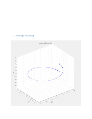
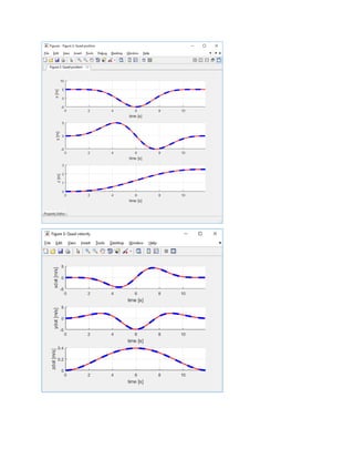
2) Developing controllers to track the smooth generated trajectories, including linearized small angle control and altitude control.
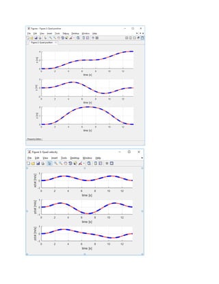
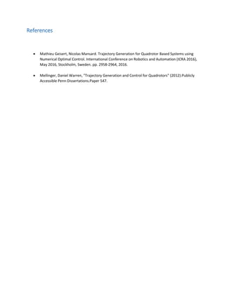
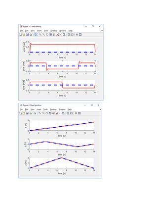
3) Extending the control to 3D trajectory tracking using position and velocity error feedback to compute commanded accelerations.

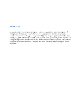
![The quadrotor is modeled as a rigid body of mass [mg] evolving in the 3-D space. The effects linked to
fluid dynamic are all neglected for our model.
3-D Trajectory Generation
We used a method based on splines that generates a minimum snap trajectory (7th
order polynomial)
between specified waypoints using the Euler-Lagrange equations. Below we explain how to generate the
minimum jerk (5th
order polynomials) trajectory using the method employed.
- We can solve the Euler-Lagrange equation
- to get the condition x(6)
= 0, such that we get the trajectory equation of the form:
- By imposing certain boundary conditions, position, velocity and acceleration constraints, we are
able to extrapolate the coefficients for the above trajectory equation
o Position constraint: x(0) = c0 = a
o Velocity constraints: x ̇(0) = c1 = 0
o Acceleration constraints: x ̈(0) = 2c2 = 0
o Boundary conditions:
Position Acceleration Velocity
t = 0 a 0 0
t = T b 0 0
Similarly, we have to solve for N-1 polynomials
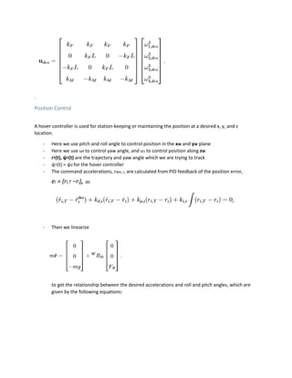
Control Schemes
Small Angle Control
We linearized the equations of motion and motor models (the two equations above in “Modelling and
Control”) in order to find the coefficients of our controller, with a selection of an operating point that
corresponds to nominal hover state,
r = r0, θ = φ = 0, ψ = ψ0, ˙ r = 0, and ˙ φ = ˙ θ = ˙ ψ = 0,
where the roll and pitch angles are small
(cφ ≈ 1, cθ ≈ 1, sφ ≈ φ, and sθ ≈ θ).
At this hover state, the nominal thrusts from the propellers must satisfy the conditions of:
F i,o = mg / 4,
and the motor speeds must satisfy conditions of:](https://image.slidesharecdn.com/quadcopterminimalsnaptrajectorygenerationalgorithmpresentation-170501035044/85/Quadcopter-minimal-snap-trajectory-generation-algorithm-presentation-4-320.jpg)

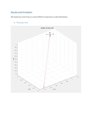
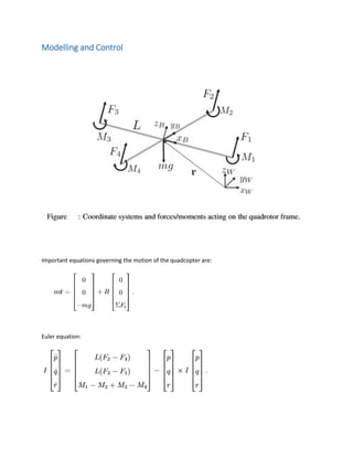
![3) Tracking path using given waypoints (Non-smooth trajectory)
waypoints = [0 0 0;
1 1 1;
2 0 2;
3 -1 1;
4 0 0]';](https://image.slidesharecdn.com/quadcopterminimalsnaptrajectorygenerationalgorithmpresentation-170501035044/85/Quadcopter-minimal-snap-trajectory-generation-algorithm-presentation-13-320.jpg)
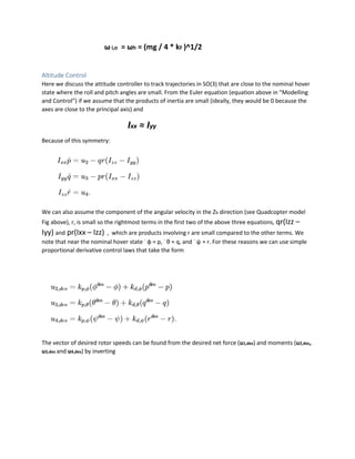
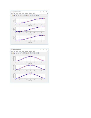
![4) Tracking using given waypoints (Using Smooth Minimal Snap Trajectory
Generation)
waypoints = [0 0 0;
1 1 1;
2 0 2;
3 -1 1;
4 0 0]';](https://image.slidesharecdn.com/quadcopterminimalsnaptrajectorygenerationalgorithmpresentation-170501035044/85/Quadcopter-minimal-snap-trajectory-generation-algorithm-presentation-15-320.jpg)