Downloaded 164 times

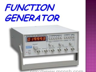
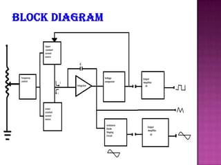

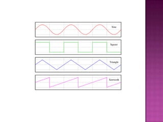

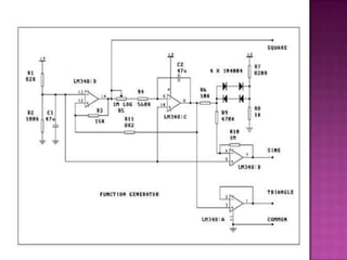


This document describes an analog function generator circuit using an ICL8038 chip. It can generate triangular, square, sine, pulse and sawtooth waveforms simultaneously. The circuit uses operational amplifiers and passive components to produce the different waveforms. It has applications in testing and troubleshooting electronic equipment by acting as a signal source. The output waveforms can be adjusted by varying potentiometers for frequency, duty cycle and distortion.