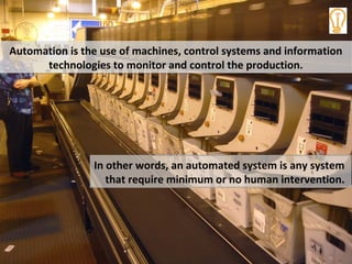
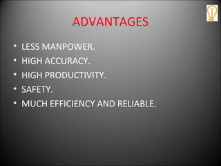
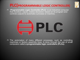
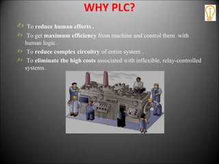
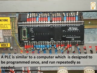
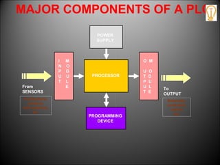
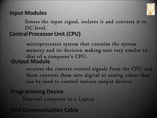
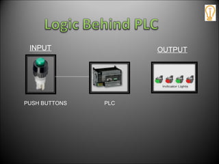
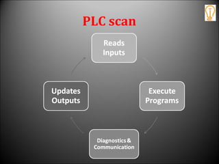
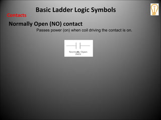
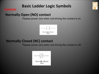
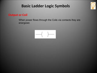
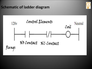
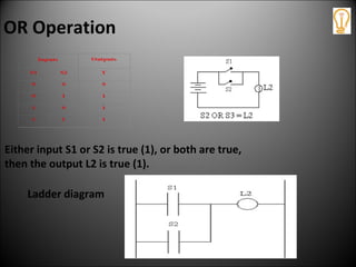
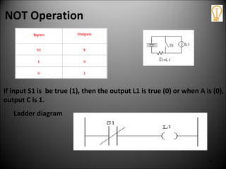
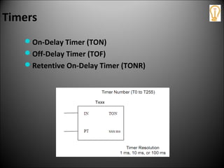
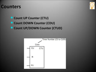
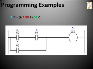
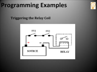
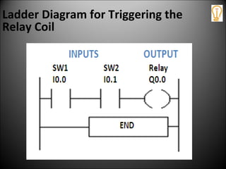
Programmable
Logic Controller
Study Material
PRESENTED BY
POWER INTEGRATED SOLUTIONS
TRICHY-17.
Welcome
The purpose of this Presentation is to
give you a very simple look
Programmable Logic Controllers and its
programming using Ladder Logic.
There is no need for you to be
familiar in any way with this field.
The only requirement is that you
enter with an open mind.
To begin with..
What is
automation?
Stage 1
AUTOMATION :
Allocation of Human control sequence to
an technical equipment is called Automation.
Egs : Tank Level Maintatinance
Automation is the use of machines, control systems and information
technologies to monitor and control the production.
Automation is the use of machines, control systems and information
technologies to monitor and control the production.
In other words, an automated system is any system
that require minimum or no human intervention.
Automation has made our life extremely
simple.
Earlier, processes were carried out by operator, hence
were much prone to human errors.
WATER TANK LEVEL MAINTAINANCE
WATER
TANK
WATER
TANK
PLC
WATER LEVEL SENSOR
0%
100%
50%
ADVANTAGES
• LESS MANPOWER.
• HIGH ACCURACY.
• HIGH PRODUCTIVITY.
• SAFETY.
• MUCH EFFICIENCY AND RELIABLE.
APPLICATIONS
• SMALL & MEDIUM ENTERPRISES.
• LARGE INDUSTRIES.
• VERY LARGE INDUSTRIES.
SMALL & MEDIUM ENTERPRISES
• FIXED TYPE PLC
• NO EXPANSION PORT
• FIXED INPUTS AND OUTPUTS
INPUTS
OUTPUTS
LARGE INDUSTRIES
• MODULAR TYPE PLC.
• EXPANSION PORT.
INPUTS
OUTPUTS
VERY LARGE INDUSTRIES
• RACK TYPE PLC.
• MORE No. Of Input and output connectors.
TYPES OF AUTOMATION
 Building automation
Example: lifts, smoke detectors
 Office automation
Example: printers, city cameras
 Scientific automation
Example: rocket launching
 Light automation
Example: street solar lightening
 Industrial automation
Example: automated bottle filling stations , steel factories etc
INDUSTRIAL AUTOMATION
 The use of Computerized or robotic devices to
complete manufacturing tasks.
PLANT
FIELD
INSTRUMENT
CONTROL SYSTEM
HARDWARE
CONTROL
SOFTWARE
CONTROL
So we can imply that with
Industrial control,
factory automation,
and PLC
(if are done well),
we can save a lot of time,
materials, energy, and money.
Where do we begin?
Let’s recall the story of an
explorer in Africa who asked
the native tribesman,
How does one eat a huge animal like an
elephant?"
The tribesman looked at the explorer in
astonishment and replied, "We eat it just like
everything else, one bite at a time."
Simple as it is, industrial control
is comprised of many smaller
circuits. By exploring and
learning simple smaller circuits,
you can learn to build a complete
automated system.
Programmable logic controllers
Lets Start With…
What is
a small computer with a built-in operating system
which monitor inputs and other variable values,
make decisions based on a stored program, and
control outputs to automate a process or machine.
Programmable logic controllers
What is
Well, that was simple isn’t it ?
Lets put it in another way..
PLC(PROGRAMMABLE LOGIC CONTROLLER)
 Programmable Logic Controller (PLC) is an industrial computer
that monitors inputs, makes decisions based on its program and
controls outputs to automate a process or machine.
 The automation of many different processes, such as controlling
machines or factory assembly lines, is done through the use of small
computers called a programmable logic controllers (PLCs).
WHY PLC?
 To reduce human efforts .
 To get maximum efficiency from machine and control them with
human logic .
 To reduce complex circuitry of entire system .
 To eliminate the high costs associated with inflexible, relay-controlled
systems.
UNDERSTANDING OF PLC (Example )
Machine can be controlled by PLC without human efforts
A PLC is similar to a computer which is designed to
be programmed once, and run repeatedly as
needed.
Elements of PLC
Let’s have al look at..
MAJOR COMPONENTS OF A PLC
PROCESSOR
POWER
SUPPLY
I M
N O
P D
U U
T L
E
O M
U O
T D
P U
U L
T E
PROGRAMMING
DEVICE
From
SENSORS
Pushbuttons,
contacts,
limit switches,
etc.
To
OUTPUT
Solenoids,
contactors,
alarms
etc.
Input Modules
Senses the input signal, isolates it and converts it to
DC level.
CentralProcessor Unit (CPU)
microprocessor system that contains the system
memory and its decision making unit very similar to
that of a computer’s CPU.
Input Modules
Senses the input signal, isolates it and converts it to
DC level.
Output Module
receives the convert control signals from the CPU and
them converts them into digital or analog values that
can be used to control various output devices.
CentralProcessor Unit (CPU)
microprocessor system that contains the system
memory and its decision making unit very similar to
that of a computer’s CPU.
Input Modules
Senses the input signal, isolates it and converts it to
DC level.
Programming Device
Personal computer or a Laptop
And Communication Cable
Output Module
receives the convert control signals from the CPU and
them converts them into digital or analog values that
can be used to control various output devices.
CentralProcessor Unit (CPU)
microprocessor system that contains the system
memory and its decision making unit very similar to
that of a computer’s CPU.
Input Modules
Senses the input signal, isolates it and converts it to
DC level.
PLC
INPUT OUTPUT
PUSH BUTTONS
PLC scan
What is a
PLC scan
PLC scan
Programming PLC
The first and still most popular
programming language used
with PLC is Ladder Logic
Programming (LAD).
They are called "ladder" diagrams
because they resemble a ladder,
with two vertical rails (supply
power) and as many "rungs"
(horizontal lines).
The first and still most popular
programming language used
with PLC is Ladder Logic
Programming (LAD).
Basic Ladder Logic Symbols
Normally Open (NO) contact
Passes power (on) when coil driving the contact is on.
Contacts
Normally Closed (NC) contact
Passes power (on) when coil driving the contact is off.
Basic Ladder Logic Symbols
Normally Open (NO) contact
Passes power (on) when coil driving the contact is on.
Contacts
Output or Coil
When power flows through the Coils via contacts they are
energized.
Basic Ladder Logic Symbols
Schematic of ladder diagram
Selecting a PLC
Criteria
• Number of logical inputs and outputs.
• Memory
• Number of special I/O modules
• Scan Time
• Communications
• Software
Functional Operation
AND Operation
OR Operation
NOT Operation
Lets have a look at their truth table
and Ladder Logic diagram
48
AND Operation
Both inputs S4 and S5 must be true (1) in order for
the output L3 to be true (1).
Ladder diagram
OR Operation
Ladder diagram
Either input S1 or S2 is true (1), or both are true,
then the output L2 is true (1).
50
NOT Operation
If input S1 is be true (1), then the output L1 is true (0) or when A is (0),
output C is 1.
Ladder diagram
Programming Functions
Timers
Counters
Timers
On-Delay Timer (TON)
Off-Delay Timer (TOF)
Retentive On-Delay Timer (TONR)
Counters
Count UP Counter (CTU)
Count DOWN Counter (CDU)
Count UP/DOWN Counter (CTUD)
ProgrammingExamples
Lets start with simple examples…
Programming Examples
D = (A AND B) OR C
Programming Examples
Triggering the Relay Coil
Ladder Diagram for Triggering the
Relay Coil
LOGON TO : www.powerintegrated.in

Introduction to PLC

  • 1.
    Programmable Logic Controller Study Material PRESENTEDBY POWER INTEGRATED SOLUTIONS TRICHY-17.
  • 2.
    Welcome The purpose ofthis Presentation is to give you a very simple look Programmable Logic Controllers and its programming using Ladder Logic. There is no need for you to be familiar in any way with this field. The only requirement is that you enter with an open mind.
  • 3.
    To begin with.. Whatis automation?
  • 4.
    Stage 1 AUTOMATION : Allocationof Human control sequence to an technical equipment is called Automation. Egs : Tank Level Maintatinance
  • 5.
    Automation is theuse of machines, control systems and information technologies to monitor and control the production. Automation is the use of machines, control systems and information technologies to monitor and control the production. In other words, an automated system is any system that require minimum or no human intervention.
  • 6.
    Automation has madeour life extremely simple.
  • 7.
    Earlier, processes werecarried out by operator, hence were much prone to human errors.
  • 8.
    WATER TANK LEVELMAINTAINANCE WATER TANK WATER TANK PLC WATER LEVEL SENSOR 0% 100% 50%
  • 9.
    ADVANTAGES • LESS MANPOWER. •HIGH ACCURACY. • HIGH PRODUCTIVITY. • SAFETY. • MUCH EFFICIENCY AND RELIABLE.
  • 10.
    APPLICATIONS • SMALL &MEDIUM ENTERPRISES. • LARGE INDUSTRIES. • VERY LARGE INDUSTRIES.
  • 11.
    SMALL & MEDIUMENTERPRISES • FIXED TYPE PLC • NO EXPANSION PORT • FIXED INPUTS AND OUTPUTS INPUTS OUTPUTS
  • 12.
    LARGE INDUSTRIES • MODULARTYPE PLC. • EXPANSION PORT. INPUTS OUTPUTS
  • 13.
    VERY LARGE INDUSTRIES •RACK TYPE PLC. • MORE No. Of Input and output connectors.
  • 14.
    TYPES OF AUTOMATION Building automation Example: lifts, smoke detectors  Office automation Example: printers, city cameras  Scientific automation Example: rocket launching  Light automation Example: street solar lightening  Industrial automation Example: automated bottle filling stations , steel factories etc
  • 15.
    INDUSTRIAL AUTOMATION  Theuse of Computerized or robotic devices to complete manufacturing tasks. PLANT FIELD INSTRUMENT CONTROL SYSTEM HARDWARE CONTROL SOFTWARE CONTROL
  • 16.
    So we canimply that with Industrial control, factory automation, and PLC (if are done well), we can save a lot of time, materials, energy, and money.
  • 17.
  • 18.
    Let’s recall thestory of an explorer in Africa who asked the native tribesman,
  • 19.
    How does oneeat a huge animal like an elephant?" The tribesman looked at the explorer in astonishment and replied, "We eat it just like everything else, one bite at a time."
  • 20.
    Simple as itis, industrial control is comprised of many smaller circuits. By exploring and learning simple smaller circuits, you can learn to build a complete automated system.
  • 21.
  • 22.
    a small computerwith a built-in operating system which monitor inputs and other variable values, make decisions based on a stored program, and control outputs to automate a process or machine. Programmable logic controllers What is
  • 23.
    Well, that wassimple isn’t it ? Lets put it in another way..
  • 24.
    PLC(PROGRAMMABLE LOGIC CONTROLLER) Programmable Logic Controller (PLC) is an industrial computer that monitors inputs, makes decisions based on its program and controls outputs to automate a process or machine.  The automation of many different processes, such as controlling machines or factory assembly lines, is done through the use of small computers called a programmable logic controllers (PLCs).
  • 25.
    WHY PLC?  Toreduce human efforts .  To get maximum efficiency from machine and control them with human logic .  To reduce complex circuitry of entire system .  To eliminate the high costs associated with inflexible, relay-controlled systems.
  • 26.
    UNDERSTANDING OF PLC(Example ) Machine can be controlled by PLC without human efforts
  • 27.
    A PLC issimilar to a computer which is designed to be programmed once, and run repeatedly as needed.
  • 28.
    Elements of PLC Let’shave al look at..
  • 29.
    MAJOR COMPONENTS OFA PLC PROCESSOR POWER SUPPLY I M N O P D U U T L E O M U O T D P U U L T E PROGRAMMING DEVICE From SENSORS Pushbuttons, contacts, limit switches, etc. To OUTPUT Solenoids, contactors, alarms etc.
  • 30.
    Input Modules Senses theinput signal, isolates it and converts it to DC level.
  • 31.
    CentralProcessor Unit (CPU) microprocessorsystem that contains the system memory and its decision making unit very similar to that of a computer’s CPU. Input Modules Senses the input signal, isolates it and converts it to DC level.
  • 32.
    Output Module receives theconvert control signals from the CPU and them converts them into digital or analog values that can be used to control various output devices. CentralProcessor Unit (CPU) microprocessor system that contains the system memory and its decision making unit very similar to that of a computer’s CPU. Input Modules Senses the input signal, isolates it and converts it to DC level.
  • 33.
    Programming Device Personal computeror a Laptop And Communication Cable Output Module receives the convert control signals from the CPU and them converts them into digital or analog values that can be used to control various output devices. CentralProcessor Unit (CPU) microprocessor system that contains the system memory and its decision making unit very similar to that of a computer’s CPU. Input Modules Senses the input signal, isolates it and converts it to DC level.
  • 34.
  • 35.
  • 36.
  • 37.
  • 38.
  • 39.
    The first andstill most popular programming language used with PLC is Ladder Logic Programming (LAD).
  • 40.
    They are called"ladder" diagrams because they resemble a ladder, with two vertical rails (supply power) and as many "rungs" (horizontal lines). The first and still most popular programming language used with PLC is Ladder Logic Programming (LAD).
  • 41.
    Basic Ladder LogicSymbols Normally Open (NO) contact Passes power (on) when coil driving the contact is on. Contacts
  • 42.
    Normally Closed (NC)contact Passes power (on) when coil driving the contact is off. Basic Ladder Logic Symbols Normally Open (NO) contact Passes power (on) when coil driving the contact is on. Contacts
  • 43.
    Output or Coil Whenpower flows through the Coils via contacts they are energized. Basic Ladder Logic Symbols
  • 44.
  • 45.
    Selecting a PLC Criteria •Number of logical inputs and outputs. • Memory • Number of special I/O modules • Scan Time • Communications • Software
  • 46.
  • 47.
    Lets have alook at their truth table and Ladder Logic diagram
  • 48.
    48 AND Operation Both inputsS4 and S5 must be true (1) in order for the output L3 to be true (1). Ladder diagram
  • 49.
    OR Operation Ladder diagram Eitherinput S1 or S2 is true (1), or both are true, then the output L2 is true (1).
  • 50.
    50 NOT Operation If inputS1 is be true (1), then the output L1 is true (0) or when A is (0), output C is 1. Ladder diagram
  • 51.
  • 52.
    Timers On-Delay Timer (TON) Off-DelayTimer (TOF) Retentive On-Delay Timer (TONR)
  • 53.
    Counters Count UP Counter(CTU) Count DOWN Counter (CDU) Count UP/DOWN Counter (CTUD)
  • 54.
  • 55.
  • 56.
  • 57.
    Ladder Diagram forTriggering the Relay Coil
  • 58.
    LOGON TO :www.powerintegrated.in