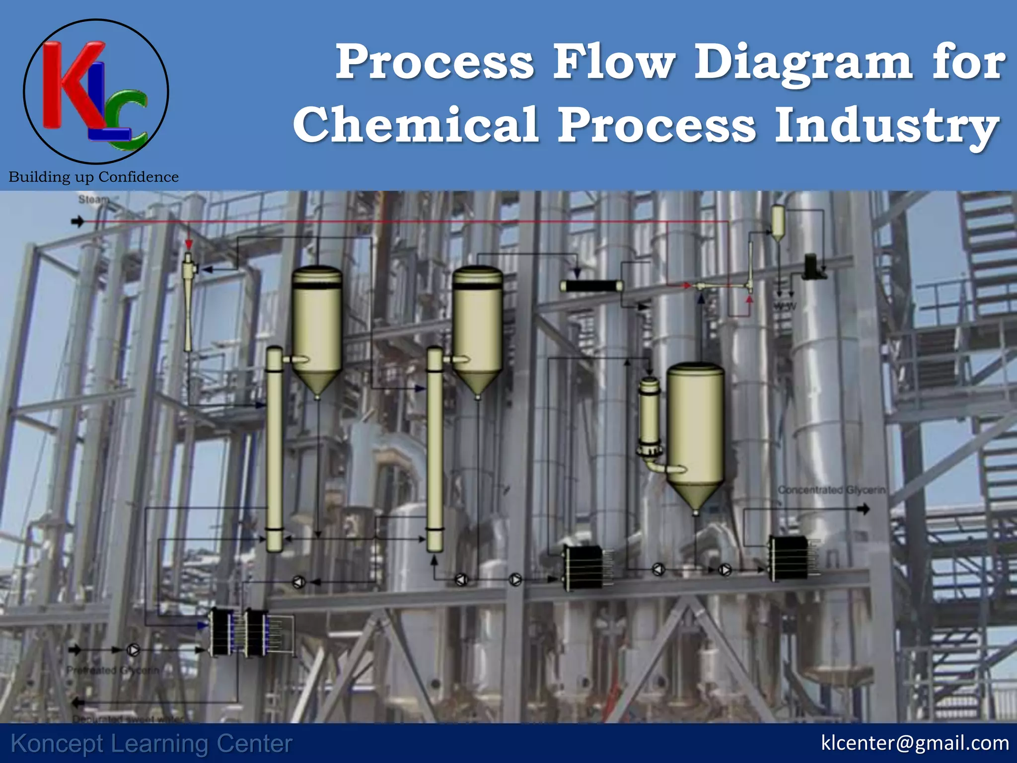
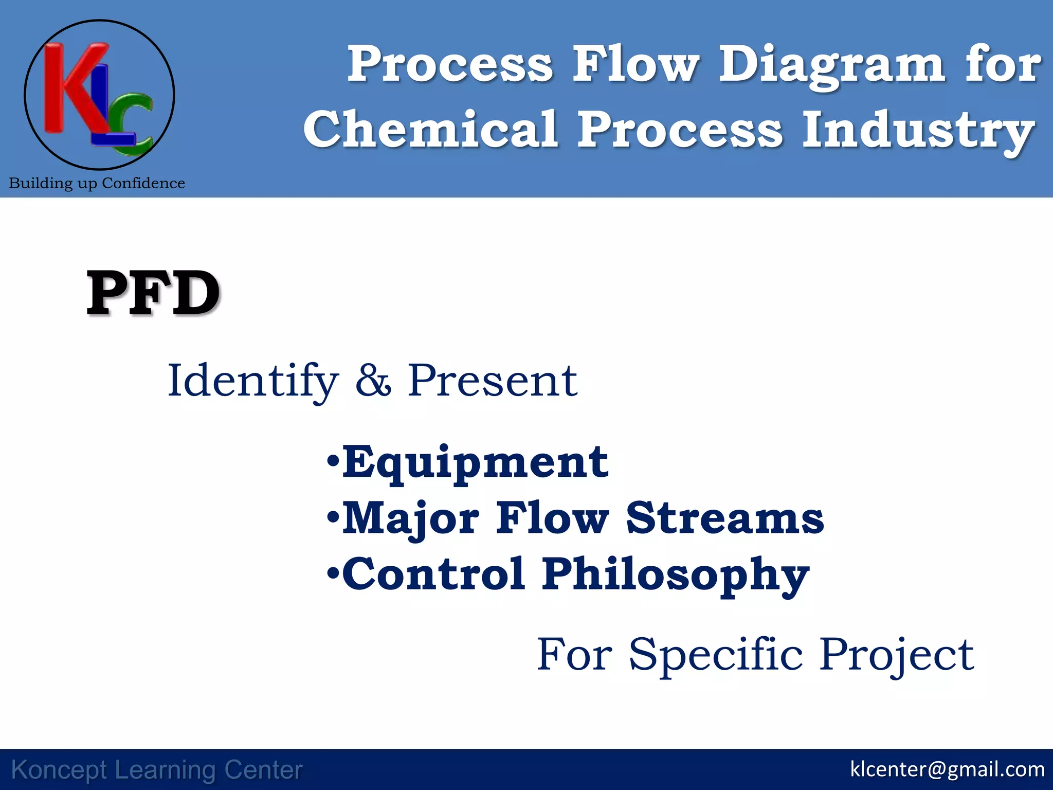
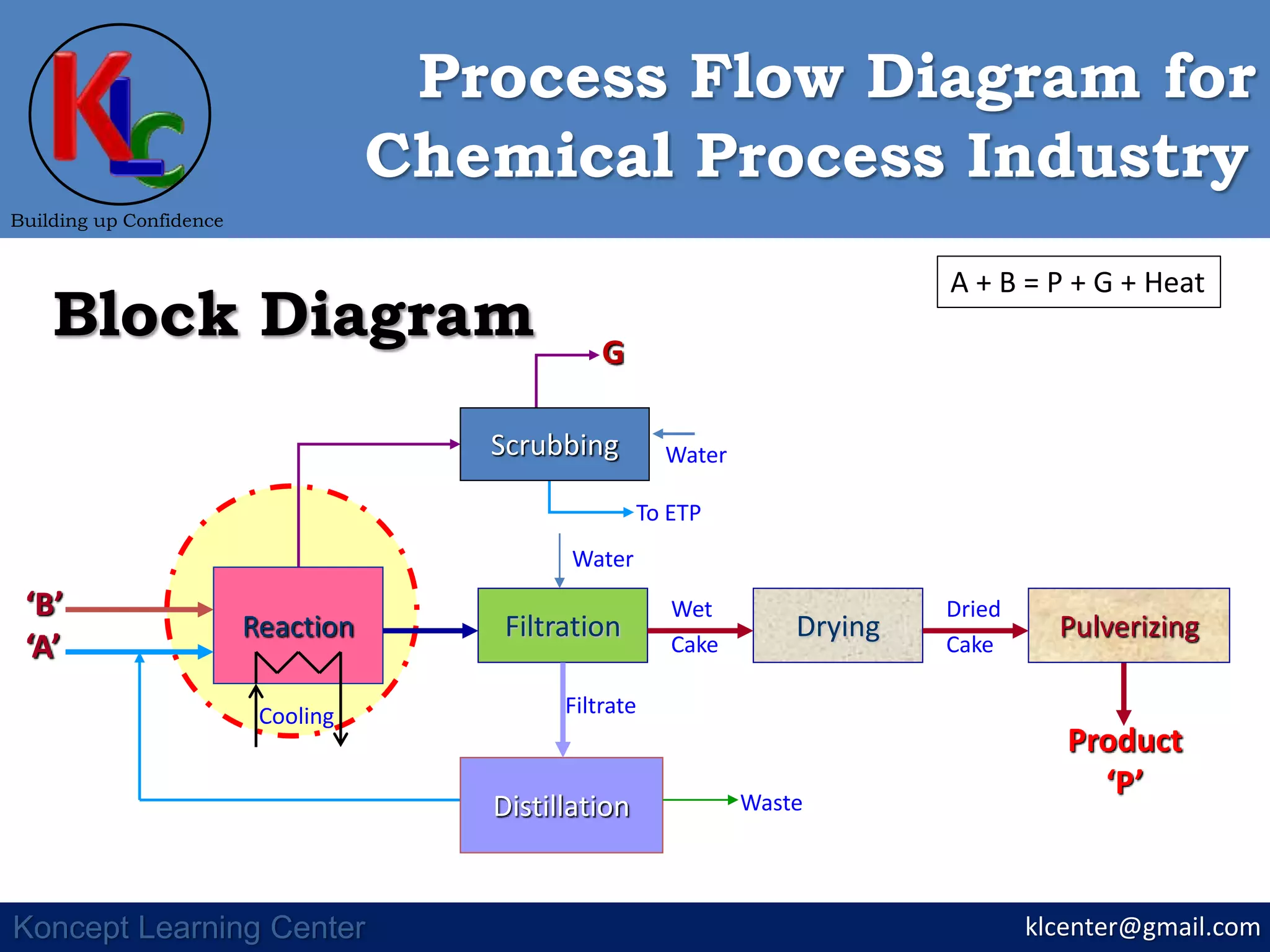
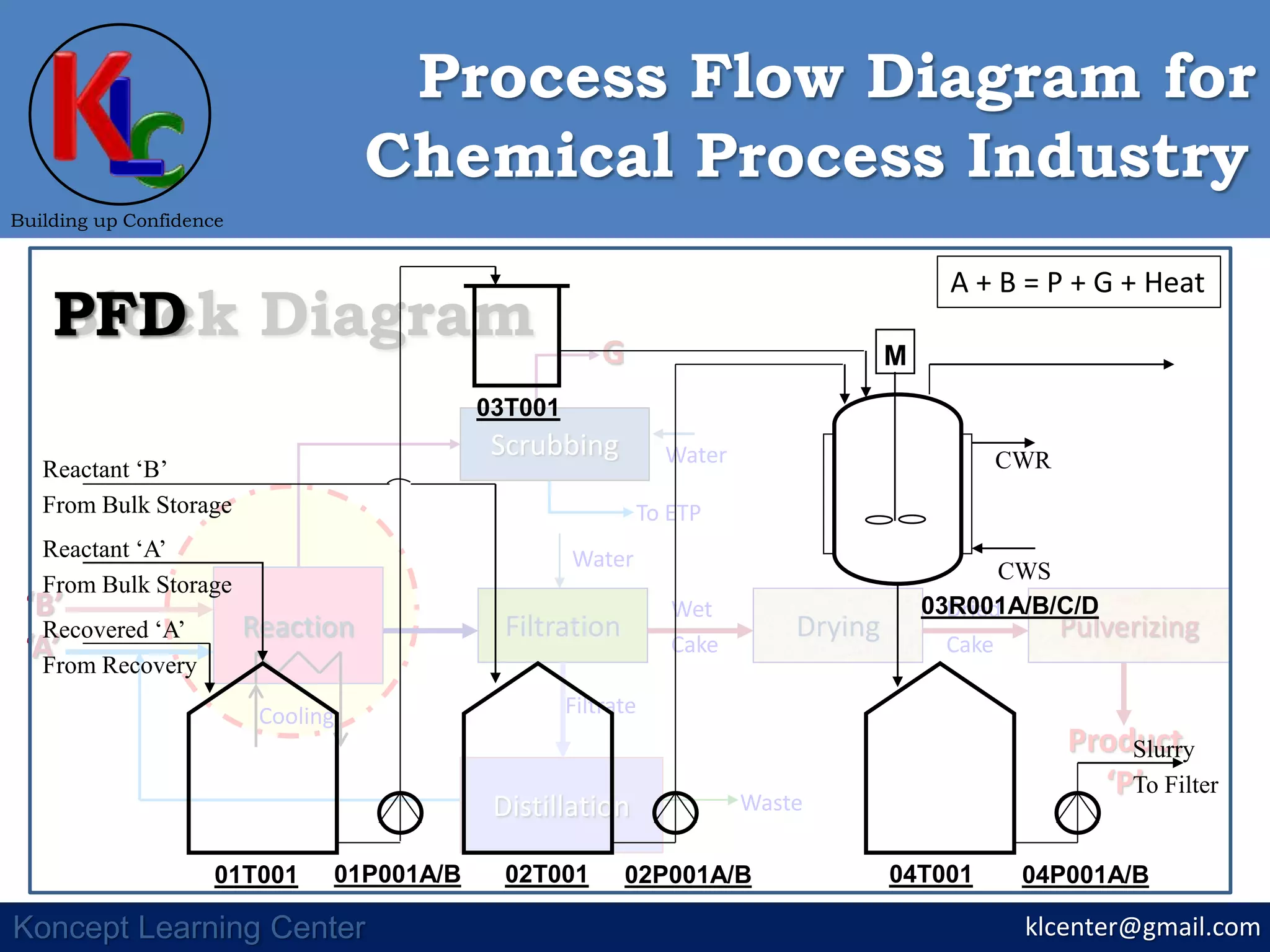
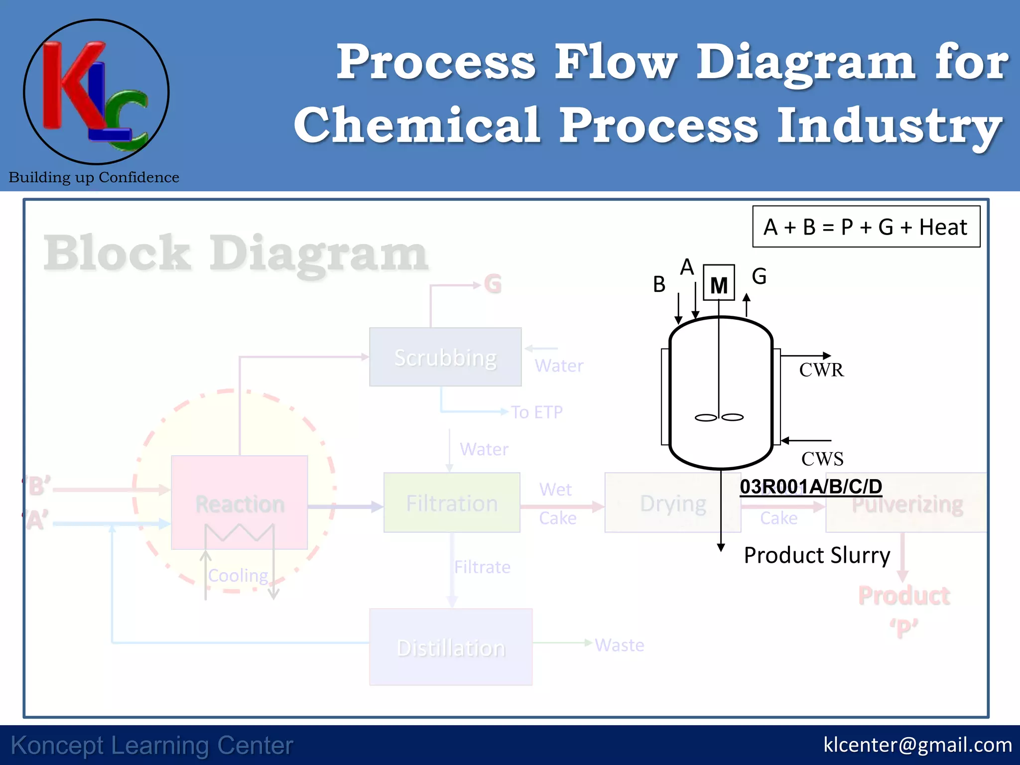
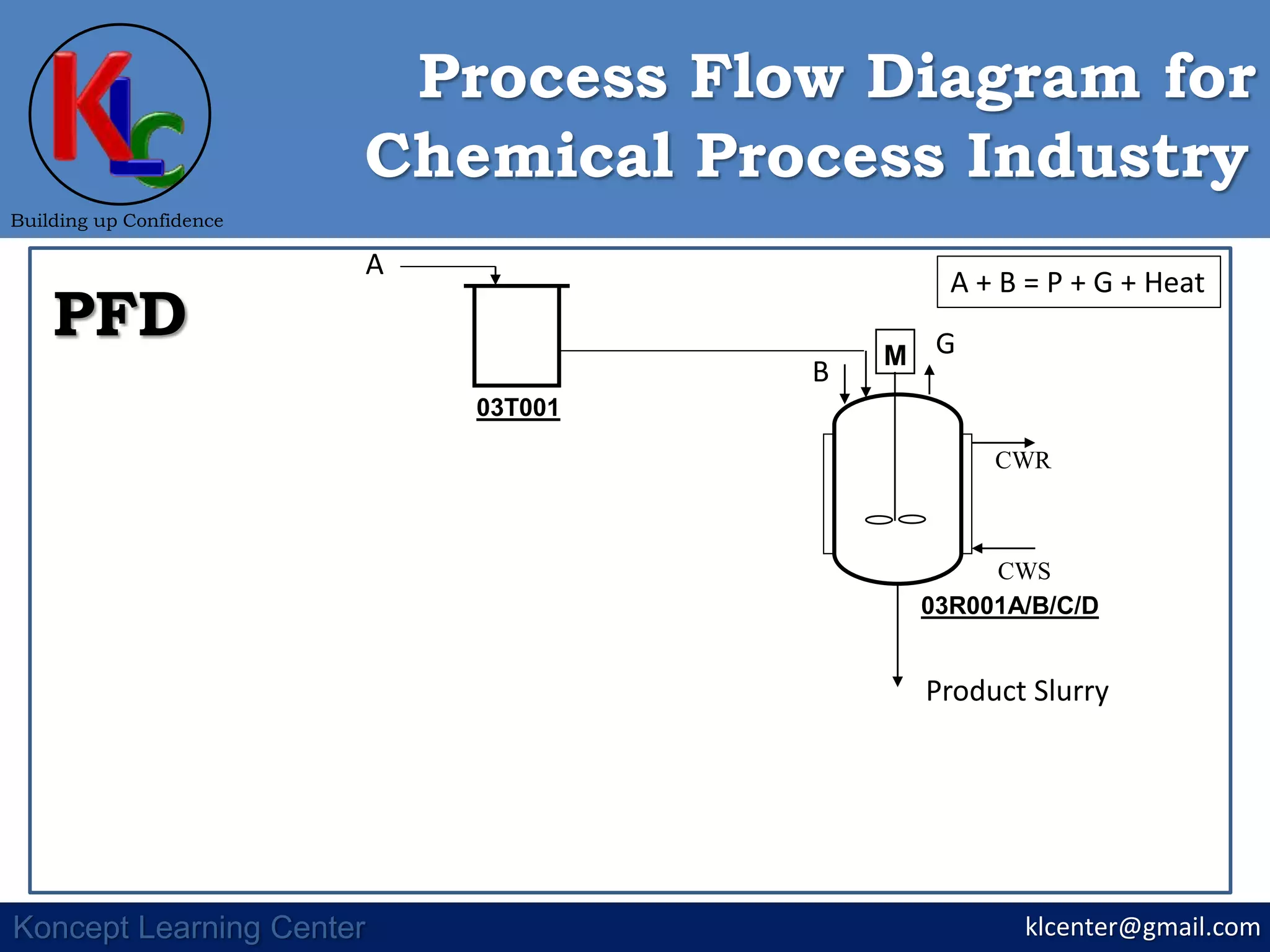
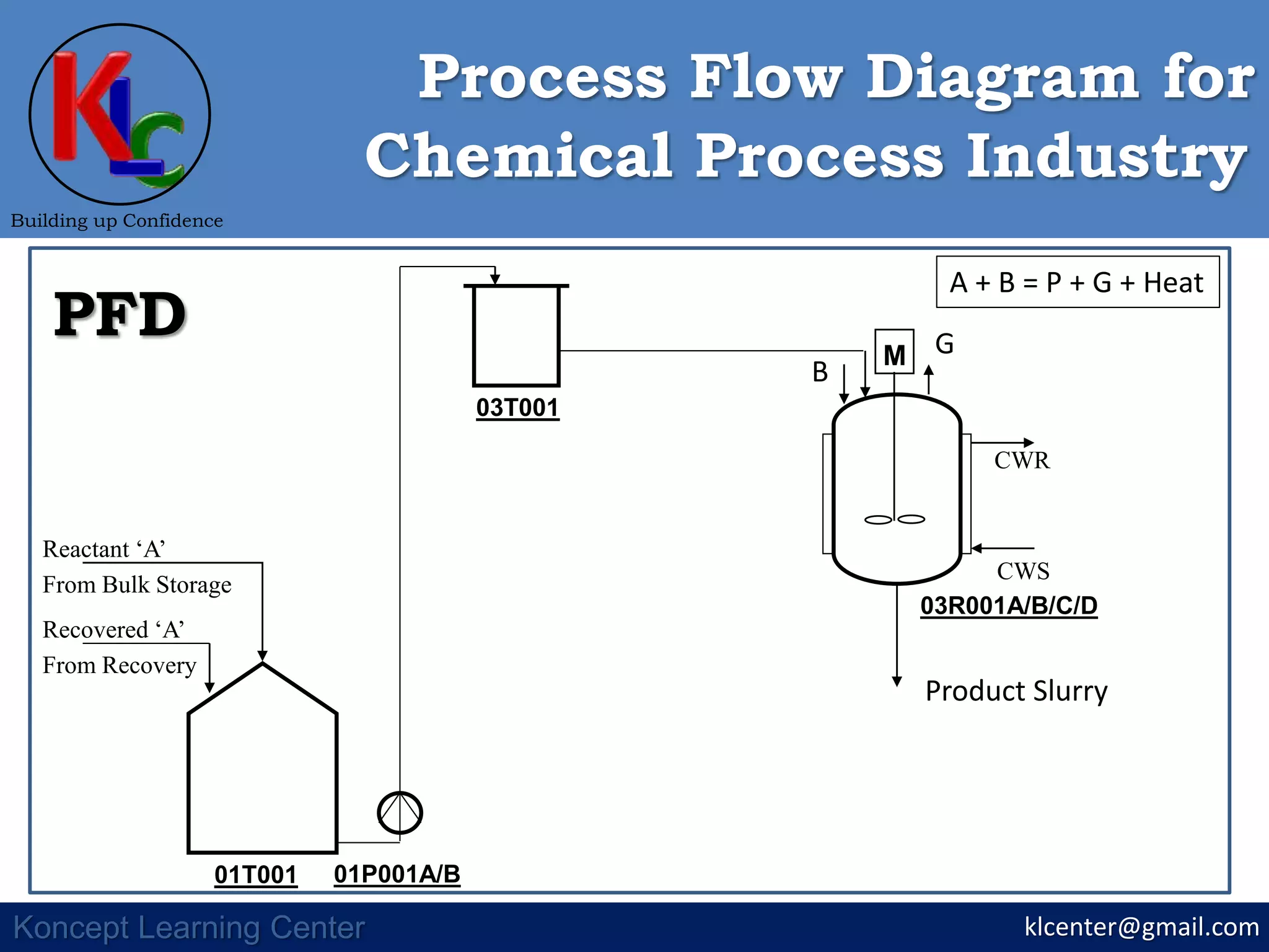
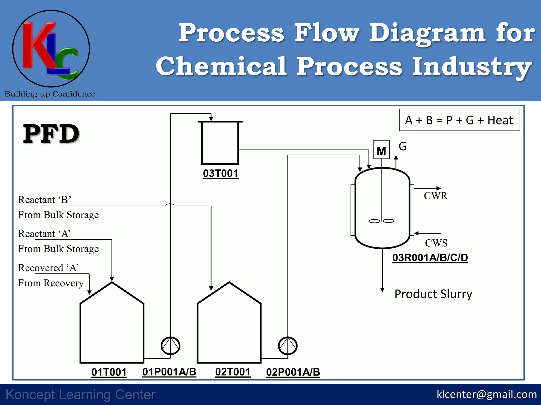
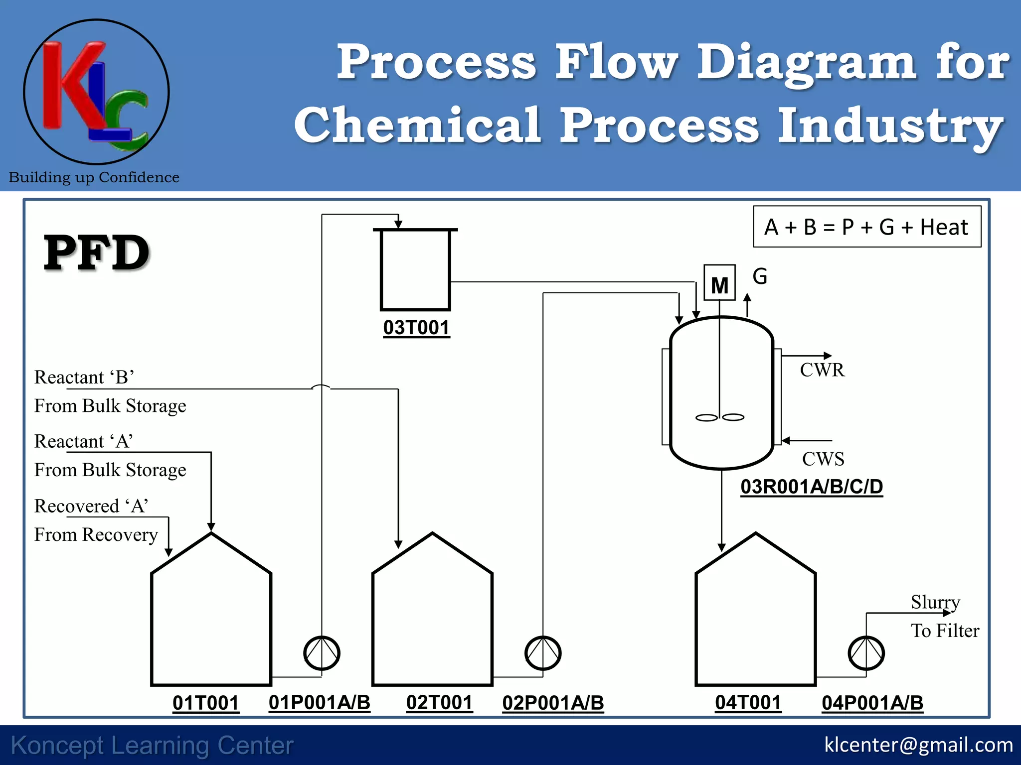
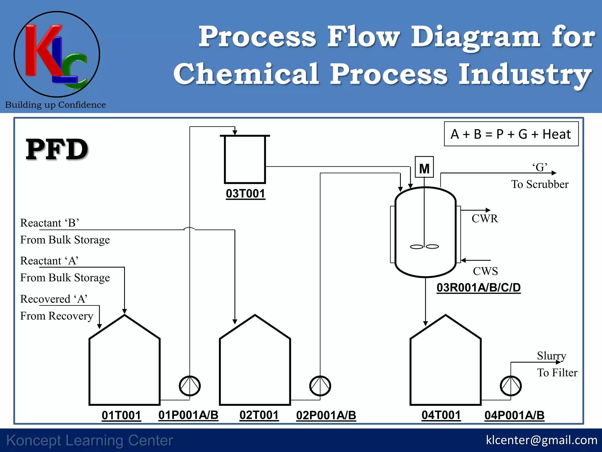
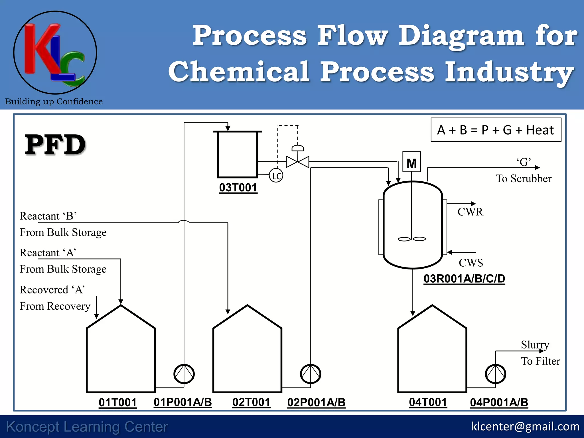
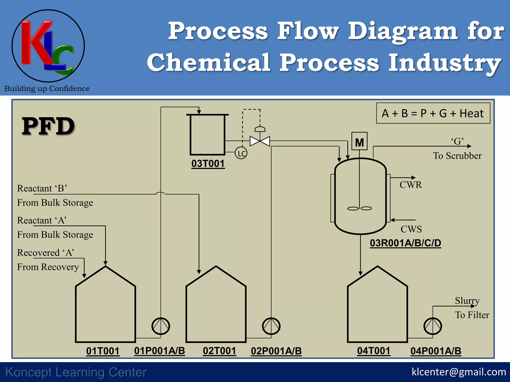
The document presents a process flow diagram (PFD) for a chemical process. It shows the major equipment, streams, and process steps involved, including: reaction of reactants A and B to form products P and G, cooling, filtration, drying, distillation, and scrubbing. Reactants A and B are sourced from bulk storage and any recovered A is also fed in. The slurry goes to filtration and G is sent to a scrubber. The PFD aims to identify and depict the key components and flow paths for a specific chemical project.
2. klcenter@gmail.com
Building up Confidence
Koncept Learning Center
Chemical Process Industry
Process Flow Diagram for
PFD
Identify & Present
•Equipment
•Major Flow Streams
•Control Philosophy
For Specific Project
3. klcenter@gmail.com
Building up Confidence
Koncept Learning Center
Chemical Process Industry
Process Flow Diagram for
Block Diagram
Reaction
Cooling
Filtration Drying
Distillation
Filtrate
Wet
Cake
Pulverizing
Dried
Cake
Product
‘P’
Water
G
To ETP
‘B’
‘A’
Scrubbing
Water
Waste
A + B = P + G + Heat
4. klcenter@gmail.com
Building up Confidence
Koncept Learning Center
Chemical Process Industry
Process Flow Diagram for
Block Diagram
Reaction
Cooling
Filtration Drying
Distillation
Filtrate
Wet
Cake
Pulverizing
Dried
Cake
Product
‘P’
Water
G
To ETP
‘B’
‘A’
Scrubbing
Water
Waste
M
01T001 02T001 04T00101P001A/B 02P001A/B 04P001A/B
03T001
03R001A/B/C/D
CWR
CWS
Slurry
To Filter
Reactant ‘B’
From Bulk Storage
Reactant ‘A’
From Bulk Storage
Recovered ‘A’
From Recovery
PFD
A + B = P + G + Heat
5. M
01T001 02T001 04T00101P001A/B 02P001A/B 04P001A/B
03T001
03R001A/B/C/D
CWR
CWS
Slurry
To Filter
Reactant ‘B’
From Bulk Storage
Reactant ‘A’
From Bulk Storage
Recovered ‘A’
From Recovery
klcenter@gmail.com
Building up Confidence
Koncept Learning Center
Chemical Process Industry
Process Flow Diagram for
PFD
A + B = P + G + Heat
6. klcenter@gmail.com
Building up Confidence
Koncept Learning Center
Chemical Process Industry
Process Flow Diagram for
Block Diagram
Reaction
Cooling
Filtration Drying
Distillation
Filtrate
Wet
Cake
Pulverizing
Dried
Cake
Product
‘P’
Water
G
To ETP
‘B’
‘A’
Scrubbing
Water
Waste
M
03R001A/B/C/D
CWR
CWS
B
A G
Product Slurry
A + B = P + G + Heat
9. M
03R001A/B/C/D
CWR
CWS
klcenter@gmail.com
Building up Confidence
Koncept Learning Center
Chemical Process Industry
Process Flow Diagram for
PFD
03T001
01T001 01P001A/B
Reactant ‘A’
From Bulk Storage
Recovered ‘A’
From Recovery
02T001 02P001A/B
Reactant ‘B’
From Bulk Storage
G
Product Slurry
A + B = P + G + Heat
10. M
03R001A/B/C/D
CWR
CWS
klcenter@gmail.com
Building up Confidence
Koncept Learning Center
Chemical Process Industry
Process Flow Diagram for
PFD
03T001
01T001 01P001A/B
Reactant ‘A’
From Bulk Storage
Recovered ‘A’
From Recovery
02T001 02P001A/B
Reactant ‘B’
From Bulk Storage
04T001 04P001A/B
Slurry
To Filter
G
A + B = P + G + Heat
11. M
01T001 02T001 04T00101P001A/B 02P001A/B 04P001A/B
03T001
03R001A/B/C/D
CWR
CWS
Slurry
To Filter
Reactant ‘B’
From Bulk Storage
Reactant ‘A’
From Bulk Storage
Recovered ‘A’
From Recovery
klcenter@gmail.com
Building up Confidence
Koncept Learning Center
Chemical Process Industry
Process Flow Diagram for
PFD ‘G’
To Scrubber
A + B = P + G + Heat
12. M
01T001 02T001 04T00101P001A/B 02P001A/B 04P001A/B
03T001
03R001A/B/C/D
CWR
CWS
Slurry
To Filter
Reactant ‘B’
From Bulk Storage
Reactant ‘A’
From Bulk Storage
Recovered ‘A’
From Recovery
klcenter@gmail.com
Building up Confidence
Koncept Learning Center
Chemical Process Industry
Process Flow Diagram for
PFD ‘G’
To Scrubber
A + B = P + G + Heat
LC
13. M
01T001 02T001 04T00101P001A/B 02P001A/B 04P001A/B
03T001
03R001A/B/C/D
CWR
CWS
Slurry
To Filter
Reactant ‘B’
From Bulk Storage
Reactant ‘A’
From Bulk Storage
Recovered ‘A’
From Recovery
klcenter@gmail.com
Building up Confidence
Koncept Learning Center
Chemical Process Industry
Process Flow Diagram for
PFD ‘G’
To Scrubber
A + B = P + G + Heat
LC