Downloaded 10,859 times


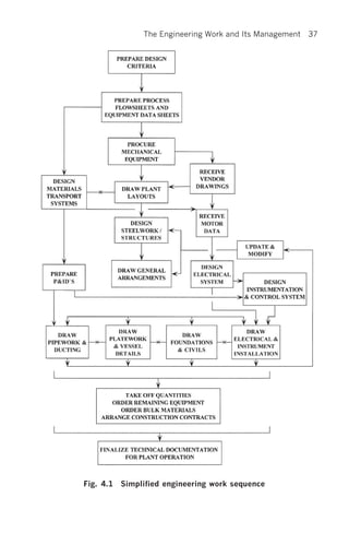
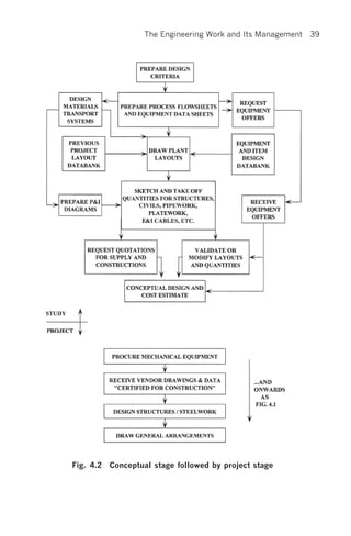


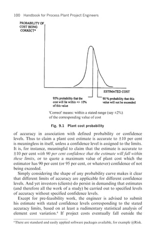


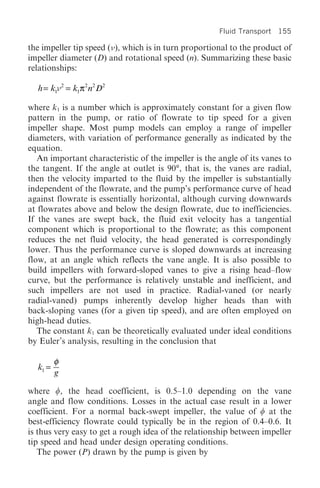
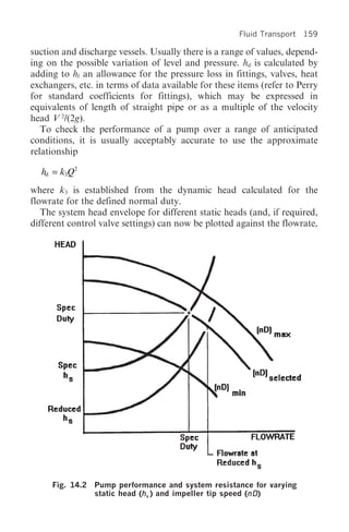


This document is the table of contents for a book on process plant project engineering. It lists 20 chapters that cover topics such as conceptual development, engineering development, detail design, documentation control, construction, and commissioning of process plants. The table of contents provides high-level descriptions of the types of topics that will be discussed in each chapter, such as plant layout and modeling, fluid transport systems, construction contracts, and commissioning procedures. It sets up the structure and flow for the information that will be presented in the full book.


