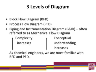
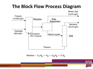
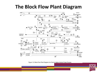
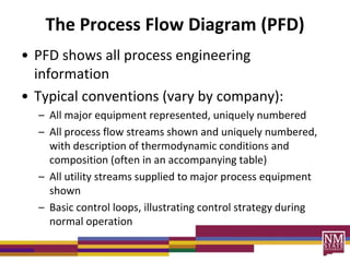
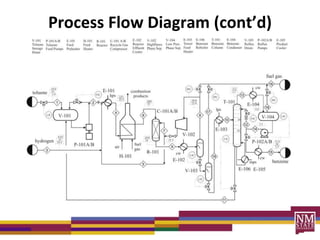
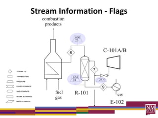
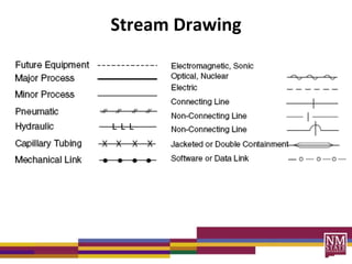
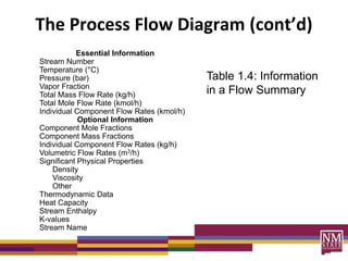
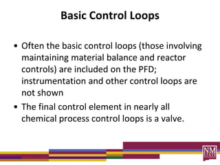
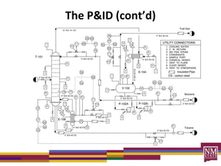
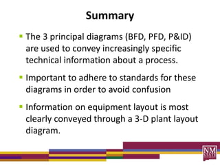
SlideShare a Scribd company logo
Chemical Process Diagrams
The most effective way of
communicating information
about a process is through the
use of flow diagrams.
Outline
• Flow Diagrams
– Block Flow Diagrams (BFD)
– Process Flow Diagrams (PFD)
– Piping and Instrument Diagrams (P&ID)
• Other common diagrams
• 3-D plant layout diagrams
3 Levels of Diagram
• Block Flow Diagram (BFD)
• Process Flow Diagram (PFD)
• Piping and Instrumentation Diagram (P&ID) – often
referred to as Mechanical Flow Diagram
Complexity Conceptual
increases understanding
increases
As chemical engineers, we are most familiar with
BFD and PFD.
The Block Flow Diagram (BFD)
• BFD shows overall processing picture of a
chemical complex
– Flow of raw materials and products may be
included on a BFD
– BFD is a superficial view of facility – Ch E
information is missing
Block Flow Diagrams (BFD)
• Emphasis not on details regarding blocks;
focus on flow of streams through process.
• Conventions:
1. Operations shown by blocks
2. Major flow lines shown with arrows giving flow direction
3. Flow goes from left to right whenever possible
4. Light streams toward top, heavy streams toward bottom
5. Critical information unique to the process supplied (i.e., reaction
stoichiometry, conversion)
6. Avoid crossing lines; horizontal continuous, vertical broken.
7. Simplified material balance (overall)
Definitions of BFD
• Block Flow Process Diagram
– Figure 1.1
– Similar to sketches in material and energy
balances
• Block Flow Plant Diagram
– Figure 1.2
– Gives a general view of a large complex plant
The Block Flow Process Diagram
The Block Flow Plant Diagram
The Process Flow Diagram (PFD)
• PFD shows all process engineering
information
• Typical conventions (vary by company):
– All major equipment represented, uniquely numbered
– All process flow streams shown and uniquely numbered,
with description of thermodynamic conditions and
composition (often in an accompanying table)
– All utility streams supplied to major process equipment
shown
– Basic control loops, illustrating control strategy during
normal operation
The Process Flow Diagram (cont’d)
– The topology of the process – showing the
connectivity of all the streams and the equipment
• Example for toluene HDA – Figures 1.3 and 1.5
• Tables 1.2 and 1.4 – list information that should be on
the PFD but cannot fit
• Use appropriate conventions – consistency is important
in communication of process information
• ex. Table 1.2
Process Flow Diagram (cont’d)
Figure C.1 Process Flow Diagram for the
Production of Allyl Chloride (Reaction Section)
Equipment Numbering
• XX-YZZ A/B/…
– XX represents a 1- or 2-letter designation for the
equipment (P = pump)
– Y is the 1 or 2 digit unit number (1-99)
– ZZ designates equipment number of unit (1-99)
– A/B/… represents presence of spare equipment
Equipment Numbering (cont’d)
• T-905 is the 5th tower in unit nine hundred
• P-301 A/B is the 1st Pump in unit three
hundred plus a spare
• Use univocal letters for new equipment
– Ex. Turbine use Tb or J not T (used for tower)
– Replace old vessel V-302 with a new one of
different design - use V-319 (e.g.) not V-302 –
since it may be confused with original V-302
Stream Numbering & Drawing
• Number streams left to right when possible
• Horizontal lines are dominant
yes no no
Stream Numbering & Drawing (cont’d)
• Add arrows for
– change in direction
– inlet of equipment
• Utility streams
– use convention in Table 1.3
– lps, cw, fg, etc.
Stream Information
• Since diagrams are small, not much stream
information can be included
• Include important data – around reactors and
towers, etc.
– Flags are used – see toluene HDA diagram
– Full stream data, as indicated in Table 1.4, are
included in a separate flow summary table – see
Table 1.5
Stream Numbering & Drawing (cont’d)
Stream Information - Flags
Stream Drawing
The Process Flow Diagram (cont’d)
Essential Information
Stream Number
Temperature (°C)
Pressure (bar)
Vapor Fraction
Total Mass Flow Rate (kg/h)
Total Mole Flow Rate (kmol/h)
Individual Component Flow Rates (kmol/h)
Optional Information
Component Mole Fractions
Component Mass Fractions
Individual Component Flow Rates (kg/h)
Volumetric Flow Rates (m3/h)
Significant Physical Properties
Density
Viscosity
Other
Thermodynamic Data
Heat Capacity
Stream Enthalpy
K-values
Stream Name
Table 1.4: Information
in a Flow Summary
Basic Control Loops
• Often the basic control loops (those involving
maintaining material balance and reactor
controls) are included on the PFD;
instrumentation and other control loops are
not shown
• The final control element in nearly all
chemical process control loops is a valve.
Basic Control Loops
Basic Instrumentation Symbols
Equipment Information
• Equipment are identified by number and a
label (name) positioned above the equipment
on the PFD
• Basic data such as size and key data are
included in a separate table (Equipment
Summary Table) Table 1.7 (and Table 1.6) in
TBWS
Equipment Information
Vessel V-101 V-102
Temperature (ºC) 55 38
Pressure (bar) 2.0 24
Orientation Horizontal Vertical
MOC CS CS
Size
Height/Length (m) 5.9 3.5
Diameter (m) 1.9 1.1
Internals s.p. (splash plate)
A Section of Table 1.7: Equipment Summary
PFD Summary
• PFD, Equipment Summary Table, and Flow
Summary Table represent a complete PFD
• This information is sufficient to permit a one
to complete a preliminary estimation of
capital investment and cost of manufacture.
Piping & Instrument Diagram
• Piping & Instrument Diagram (P&ID) –
Construction Bible
• Contains: plant construction information
(piping, process, instrumentation)
• P&ID info explained in Tables 1.8 and 1.9
• Instrumentation conventions shown in Fig.
1.10
Piping & Instrumentation Diagram (P&ID)
• support documents of the PFD used for planning for plant
construction and maintaining the plant thereafter
• Each PFD requires many P&IDs to provide the necessary data
• Used as a checklist at the final walk-through prior to start up
to assure each detail has been attended to
• Use by/to
– MEs and CEs to build/install equipment
– Instrument engineers to specify/install/check control systems
– Piping engineers to develop plant layout and elevation drawings
– Project engineers to develop plant and construction schedules
The P&ID (cont’d)
Look at V-102 on P&ID
• V-102 contains an LE (Level Element)
• LE senses liquid level in separator and adjusts
flow rate leaving, by opening or closing a
valve, depending on liquid level
• Together, the LE and valve represent a
feedback control loop
Valve Symbols
More Valve Symbols
Other Common Diagrams
• Plot Plans – plan or map drawn looking down
on plant (drawn to scale with all major
equipment identified)
• Elevation Diagrams – show view from side and
give information about equipments distance
from ground
• Foundation drawings
• Electrical drawings
Plot Plan
Plot Plan
Elevation Diagram
Elevation Drawing
Foundation Drawing
Electrical Drawing
Other Common Diagrams (cont’d)
• Piping Isometrics – show piping in 3-
dimensions
• Vessel Sketches – show key dimensions of
equipment and locations of inlet and outlet
nozzles etc.
Scale Models and Virtual Plants
• 25 yr ago physical models used for review
• Now virtual or electronic models are
generated using software (3D plant diagrams)
• Purpose of Models – catch errors such as
– Piping clashes
– Misaligned piping
– Equipment not easily accessed
– Sample points not easily reached by operators
3-D Plant
Diagrams
Summary
 The 3 principal diagrams (BFD, PFD, P&ID)
are used to convey increasingly specific
technical information about a process.
 Important to adhere to standards for these
diagrams in order to avoid confusion
 Information on equipment layout is most
clearly conveyed through a 3-D plant layout
diagram.

More Related Content

What's hot

Process Plant design fundementals
Process Plant design fundementalsProcess Plant design fundementals
Process Plant design fundementals
Greg Pajak - P. Tech (Eng.), ISA84 SIS Expert
 
fundamentals of Piping engineering
fundamentals of Piping engineeringfundamentals of Piping engineering
fundamentals of Piping engineering
MobinVarghese8
 
ipec.info | Pfd p&id
ipec.info | Pfd p&idipec.info | Pfd p&id
ipec.info | Pfd p&id
IPEC
 
Normal Operation of Steam Reformers on Hydrogen Plants
Normal Operation of Steam Reformers on Hydrogen PlantsNormal Operation of Steam Reformers on Hydrogen Plants
Normal Operation of Steam Reformers on Hydrogen Plants
Gerard B. Hawkins
 
PIPING & INSTRUMENTATION DIAGRAM.pdf
PIPING & INSTRUMENTATION DIAGRAM.pdfPIPING & INSTRUMENTATION DIAGRAM.pdf
PIPING & INSTRUMENTATION DIAGRAM.pdf
MassinissaHamel
 
HTRI PRESENTATION.pdf
HTRI PRESENTATION.pdfHTRI PRESENTATION.pdf
HTRI PRESENTATION.pdf
ssuserbd5784
 
Process Flow Diagram
Process Flow DiagramProcess Flow Diagram
Process Flow Diagram
Pankaj Khandelwal
 
oil and gas - P&ID symbols .pdf
oil and gas - P&ID symbols .pdfoil and gas - P&ID symbols .pdf
oil and gas - P&ID symbols .pdf
nelsonhuatay
 
Pressure Relief Devices_Presenation
Pressure Relief Devices_PresenationPressure Relief Devices_Presenation
Pressure Relief Devices_Presenation
sumit handa
 
Piping basics knowledge
Piping basics knowledgePiping basics knowledge
Piping basics knowledge
ARINDAM BANERJEE
 
Piping Design ppt.pdf
Piping Design ppt.pdfPiping Design ppt.pdf
Piping Design ppt.pdf
SyedMoazzamAliAli1
 
Piping presentation part ii 2
Piping presentation part ii 2Piping presentation part ii 2
Piping presentation part ii 2
raghunathan janarthanan
 
Hydrogen Production Unit
Hydrogen Production UnitHydrogen Production Unit
Hydrogen Production Unit
Magdy Abo Hashish
 
Three Phase Separators
Three Phase SeparatorsThree Phase Separators
Three Phase Separators
Muhammad Atif Ilyas
 
Piping material-specification
Piping material-specificationPiping material-specification
Piping material-specification
ChiragShah127
 
EMEC130 P&ID Symbol Primer
EMEC130 P&ID Symbol PrimerEMEC130 P&ID Symbol Primer
EMEC130 P&ID Symbol Primer
John Todora
 
Steam Reforming - Types of Reformer Design
Steam Reforming - Types of Reformer DesignSteam Reforming - Types of Reformer Design
Steam Reforming - Types of Reformer Design
Gerard B. Hawkins
 
what is process piping
what is process pipingwhat is process piping
what is process piping
Varun Patel
 
Design Checklist-Instrumentation & Control Systems (typical / guideline)
Design Checklist-Instrumentation & Control Systems (typical / guideline)Design Checklist-Instrumentation & Control Systems (typical / guideline)
Design Checklist-Instrumentation & Control Systems (typical / guideline)
Stephanus Roux C Eng , IntPE(uk) , FIET
 
psv specifications
psv specificationspsv specifications
psv specifications
Kumar Natarajan
 

What's hot (20)

Process Plant design fundementals
Process Plant design fundementalsProcess Plant design fundementals
Process Plant design fundementals
 
fundamentals of Piping engineering
fundamentals of Piping engineeringfundamentals of Piping engineering
fundamentals of Piping engineering
 
ipec.info | Pfd p&id
ipec.info | Pfd p&idipec.info | Pfd p&id
ipec.info | Pfd p&id
 
Normal Operation of Steam Reformers on Hydrogen Plants
Normal Operation of Steam Reformers on Hydrogen PlantsNormal Operation of Steam Reformers on Hydrogen Plants
Normal Operation of Steam Reformers on Hydrogen Plants
 
PIPING & INSTRUMENTATION DIAGRAM.pdf
PIPING & INSTRUMENTATION DIAGRAM.pdfPIPING & INSTRUMENTATION DIAGRAM.pdf
PIPING & INSTRUMENTATION DIAGRAM.pdf
 
HTRI PRESENTATION.pdf
HTRI PRESENTATION.pdfHTRI PRESENTATION.pdf
HTRI PRESENTATION.pdf
 
Process Flow Diagram
Process Flow DiagramProcess Flow Diagram
Process Flow Diagram
 
oil and gas - P&ID symbols .pdf
oil and gas - P&ID symbols .pdfoil and gas - P&ID symbols .pdf
oil and gas - P&ID symbols .pdf
 
Pressure Relief Devices_Presenation
Pressure Relief Devices_PresenationPressure Relief Devices_Presenation
Pressure Relief Devices_Presenation
 
Piping basics knowledge
Piping basics knowledgePiping basics knowledge
Piping basics knowledge
 
Piping Design ppt.pdf
Piping Design ppt.pdfPiping Design ppt.pdf
Piping Design ppt.pdf
 
Piping presentation part ii 2
Piping presentation part ii 2Piping presentation part ii 2
Piping presentation part ii 2
 
Hydrogen Production Unit
Hydrogen Production UnitHydrogen Production Unit
Hydrogen Production Unit
 
Three Phase Separators
Three Phase SeparatorsThree Phase Separators
Three Phase Separators
 
Piping material-specification
Piping material-specificationPiping material-specification
Piping material-specification
 
EMEC130 P&ID Symbol Primer
EMEC130 P&ID Symbol PrimerEMEC130 P&ID Symbol Primer
EMEC130 P&ID Symbol Primer
 
Steam Reforming - Types of Reformer Design
Steam Reforming - Types of Reformer DesignSteam Reforming - Types of Reformer Design
Steam Reforming - Types of Reformer Design
 
what is process piping
what is process pipingwhat is process piping
what is process piping
 
Design Checklist-Instrumentation & Control Systems (typical / guideline)
Design Checklist-Instrumentation & Control Systems (typical / guideline)Design Checklist-Instrumentation & Control Systems (typical / guideline)
Design Checklist-Instrumentation & Control Systems (typical / guideline)
 
psv specifications
psv specificationspsv specifications
psv specifications
 

Viewers also liked

Co-production of allyl chloride & 1,3-dichloropropene (soil fumigant)
Co-production of allyl chloride & 1,3-dichloropropene (soil fumigant)Co-production of allyl chloride & 1,3-dichloropropene (soil fumigant)
Co-production of allyl chloride & 1,3-dichloropropene (soil fumigant)
Jae Cho
 
introduction to chemical process technology,process flow diagram and block fl...
introduction to chemical process technology,process flow diagram and block fl...introduction to chemical process technology,process flow diagram and block fl...
introduction to chemical process technology,process flow diagram and block fl...
saeed memon
 
MOIN KHAN PROJECT - Copy
MOIN KHAN PROJECT - CopyMOIN KHAN PROJECT - Copy
MOIN KHAN PROJECT - Copy
Moin Khan
 
Simbologia neumatica
Simbologia neumaticaSimbologia neumatica
Simbologia neumatica
Selene M.P
 
Fixed Bed Reactor Scale-up Checklist
Fixed Bed Reactor Scale-up ChecklistFixed Bed Reactor Scale-up Checklist
Fixed Bed Reactor Scale-up Checklist
Gerard B. Hawkins
 
Design 1
Design 1Design 1
Senior Project
Senior ProjectSenior Project
Senior Project
Mike Thompson
 
Detailed Design Report
Detailed Design ReportDetailed Design Report
Detailed Design Report
Tomos Hughes
 
Normas isa
Normas isaNormas isa
Normas isa
Karo di marco
 
Simbologia isa.
Simbologia isa.Simbologia isa.
Simbologia isa.
acpicegudomonagas
 
SIMBOLOGÍA ISA
SIMBOLOGÍA ISA SIMBOLOGÍA ISA
SIMBOLOGÍA ISA
UDO Monagas
 
Normas isa
Normas isaNormas isa
Cartilla De Controles Final
Cartilla De Controles FinalCartilla De Controles Final
Cartilla De Controles Final
Carlosfidel
 
01 p&id - 1
01 p&id - 101 p&id - 1
01 p&id - 1
MaloNe Wanger
 
Simbologia neuMATICA
Simbologia neuMATICASimbologia neuMATICA
Simbologia neuMATICA
kikolascaballero
 
El contactor
El contactorEl contactor
El contactor
Hugo Mora
 
Simbologia de hidraulica y neumatica
Simbologia de hidraulica y neumaticaSimbologia de hidraulica y neumatica
Simbologia de hidraulica y neumatica
Fernando Hernandez
 
P & i diagram
P & i diagramP & i diagram
P & i diagram
Pankaj Khandelwal
 
Valves ppt
Valves pptValves ppt
Valves ppt
tousi_hussaini
 
Simbologia neumaticos
Simbologia neumaticosSimbologia neumaticos
Simbologia neumaticos
Lander Ramírez Mayta
 

Viewers also liked (20)

Co-production of allyl chloride & 1,3-dichloropropene (soil fumigant)
Co-production of allyl chloride & 1,3-dichloropropene (soil fumigant)Co-production of allyl chloride & 1,3-dichloropropene (soil fumigant)
Co-production of allyl chloride & 1,3-dichloropropene (soil fumigant)
 
introduction to chemical process technology,process flow diagram and block fl...
introduction to chemical process technology,process flow diagram and block fl...introduction to chemical process technology,process flow diagram and block fl...
introduction to chemical process technology,process flow diagram and block fl...
 
MOIN KHAN PROJECT - Copy
MOIN KHAN PROJECT - CopyMOIN KHAN PROJECT - Copy
MOIN KHAN PROJECT - Copy
 
Simbologia neumatica
Simbologia neumaticaSimbologia neumatica
Simbologia neumatica
 
Fixed Bed Reactor Scale-up Checklist
Fixed Bed Reactor Scale-up ChecklistFixed Bed Reactor Scale-up Checklist
Fixed Bed Reactor Scale-up Checklist
 
Design 1
Design 1Design 1
Design 1
 
Senior Project
Senior ProjectSenior Project
Senior Project
 
Detailed Design Report
Detailed Design ReportDetailed Design Report
Detailed Design Report
 
Normas isa
Normas isaNormas isa
Normas isa
 
Simbologia isa.
Simbologia isa.Simbologia isa.
Simbologia isa.
 
SIMBOLOGÍA ISA
SIMBOLOGÍA ISA SIMBOLOGÍA ISA
SIMBOLOGÍA ISA
 
Normas isa
Normas isaNormas isa
Normas isa
 
Cartilla De Controles Final
Cartilla De Controles FinalCartilla De Controles Final
Cartilla De Controles Final
 
01 p&id - 1
01 p&id - 101 p&id - 1
01 p&id - 1
 
Simbologia neuMATICA
Simbologia neuMATICASimbologia neuMATICA
Simbologia neuMATICA
 
El contactor
El contactorEl contactor
El contactor
 
Simbologia de hidraulica y neumatica
Simbologia de hidraulica y neumaticaSimbologia de hidraulica y neumatica
Simbologia de hidraulica y neumatica
 
P & i diagram
P & i diagramP & i diagram
P & i diagram
 
Valves ppt
Valves pptValves ppt
Valves ppt
 
Simbologia neumaticos
Simbologia neumaticosSimbologia neumaticos
Simbologia neumaticos
 

Similar to Process diagrams lecture

Chem Chapter.ppt
Chem Chapter.pptChem Chapter.ppt
Chem Chapter.ppt
Sekhar930202
 
Process flow sheet diagram
Process flow sheet diagramProcess flow sheet diagram
Process flow sheet diagram
Bahauddin Zakariya University lahore
 
Process Drawings
Process DrawingsProcess Drawings
Process Drawings
Musharif Hussain
 
Cge666 chapter 1-wk 1-2
Cge666 chapter 1-wk 1-2Cge666 chapter 1-wk 1-2
Cge666 chapter 1-wk 1-2
Fiena Azmi
 
PFD_P&ID.pdf
PFD_P&ID.pdfPFD_P&ID.pdf
PFD_P&ID.pdf
Djona Lokima
 
1T-Process-Symbols-And-Diagram.pdf
1T-Process-Symbols-And-Diagram.pdf1T-Process-Symbols-And-Diagram.pdf
1T-Process-Symbols-And-Diagram.pdf
rezarahat1
 
5_6064355360796312399.pptx
5_6064355360796312399.pptx5_6064355360796312399.pptx
5_6064355360796312399.pptx
BonsaHailu
 
P&ID Presentation.pdf
P&ID Presentation.pdfP&ID Presentation.pdf
P&ID Presentation.pdf
ShamsMohd
 
Process Flow Diagram and P&I Diagram.pptx
Process Flow Diagram and P&I Diagram.pptxProcess Flow Diagram and P&I Diagram.pptx
Process Flow Diagram and P&I Diagram.pptx
DrAyyarKandasamy
 
INDUSTRIAL CHEMICAL PROCESS DESIGN.pptx
INDUSTRIAL CHEMICAL PROCESS DESIGN.pptxINDUSTRIAL CHEMICAL PROCESS DESIGN.pptx
INDUSTRIAL CHEMICAL PROCESS DESIGN.pptx
Humphrey23
 
Bfd pfd-pid
Bfd pfd-pidBfd pfd-pid
Bfd pfd-pid
Youssef EL ARFAOUI
 
07 chapter07 loop_diagrams
07 chapter07 loop_diagrams07 chapter07 loop_diagrams
07 chapter07 loop_diagrams
John Todora
 
Chapter1-Lec1-3.pdf
Chapter1-Lec1-3.pdfChapter1-Lec1-3.pdf
Chapter1-Lec1-3.pdf
Muhammad Athar
 
Class 12 dead time, p & i diagram basics
Class 12   dead time, p & i diagram basicsClass 12   dead time, p & i diagram basics
Class 12 dead time, p & i diagram basics
Manipal Institute of Technology
 
PIPING AND INSTRUMENTATION DIAGRAMS PRESENTATION.pdf
PIPING AND INSTRUMENTATION DIAGRAMS PRESENTATION.pdfPIPING AND INSTRUMENTATION DIAGRAMS PRESENTATION.pdf
PIPING AND INSTRUMENTATION DIAGRAMS PRESENTATION.pdf
eldoctol
 
Drawings & Documents Required for Solar Projects
Drawings & Documents Required for Solar ProjectsDrawings & Documents Required for Solar Projects
Drawings & Documents Required for Solar Projects
Gensol Engineering Limited
 
instrumentation docments
instrumentation docmentsinstrumentation docments
instrumentation docments
Maria Romina Angustia
 
4554682.ppt
4554682.ppt4554682.ppt
4554682.ppt
ssusere57332
 
02 chapter02 p&ids_and_symbols_split_animations
02 chapter02 p&ids_and_symbols_split_animations02 chapter02 p&ids_and_symbols_split_animations
02 chapter02 p&ids_and_symbols_split_animations
John Todora
 
PID control for process safety.pdf
PID control for process safety.pdfPID control for process safety.pdf
PID control for process safety.pdf
SMTauseef1
 

Similar to Process diagrams lecture (20)

Chem Chapter.ppt
Chem Chapter.pptChem Chapter.ppt
Chem Chapter.ppt
 
Process flow sheet diagram
Process flow sheet diagramProcess flow sheet diagram
Process flow sheet diagram
 
Process Drawings
Process DrawingsProcess Drawings
Process Drawings
 
Cge666 chapter 1-wk 1-2
Cge666 chapter 1-wk 1-2Cge666 chapter 1-wk 1-2
Cge666 chapter 1-wk 1-2
 
PFD_P&ID.pdf
PFD_P&ID.pdfPFD_P&ID.pdf
PFD_P&ID.pdf
 
1T-Process-Symbols-And-Diagram.pdf
1T-Process-Symbols-And-Diagram.pdf1T-Process-Symbols-And-Diagram.pdf
1T-Process-Symbols-And-Diagram.pdf
 
5_6064355360796312399.pptx
5_6064355360796312399.pptx5_6064355360796312399.pptx
5_6064355360796312399.pptx
 
P&ID Presentation.pdf
P&ID Presentation.pdfP&ID Presentation.pdf
P&ID Presentation.pdf
 
Process Flow Diagram and P&I Diagram.pptx
Process Flow Diagram and P&I Diagram.pptxProcess Flow Diagram and P&I Diagram.pptx
Process Flow Diagram and P&I Diagram.pptx
 
INDUSTRIAL CHEMICAL PROCESS DESIGN.pptx
INDUSTRIAL CHEMICAL PROCESS DESIGN.pptxINDUSTRIAL CHEMICAL PROCESS DESIGN.pptx
INDUSTRIAL CHEMICAL PROCESS DESIGN.pptx
 
Bfd pfd-pid
Bfd pfd-pidBfd pfd-pid
Bfd pfd-pid
 
07 chapter07 loop_diagrams
07 chapter07 loop_diagrams07 chapter07 loop_diagrams
07 chapter07 loop_diagrams
 
Chapter1-Lec1-3.pdf
Chapter1-Lec1-3.pdfChapter1-Lec1-3.pdf
Chapter1-Lec1-3.pdf
 
Class 12 dead time, p & i diagram basics
Class 12   dead time, p & i diagram basicsClass 12   dead time, p & i diagram basics
Class 12 dead time, p & i diagram basics
 
PIPING AND INSTRUMENTATION DIAGRAMS PRESENTATION.pdf
PIPING AND INSTRUMENTATION DIAGRAMS PRESENTATION.pdfPIPING AND INSTRUMENTATION DIAGRAMS PRESENTATION.pdf
PIPING AND INSTRUMENTATION DIAGRAMS PRESENTATION.pdf
 
Drawings & Documents Required for Solar Projects
Drawings & Documents Required for Solar ProjectsDrawings & Documents Required for Solar Projects
Drawings & Documents Required for Solar Projects
 
instrumentation docments
instrumentation docmentsinstrumentation docments
instrumentation docments
 
4554682.ppt
4554682.ppt4554682.ppt
4554682.ppt
 
02 chapter02 p&ids_and_symbols_split_animations
02 chapter02 p&ids_and_symbols_split_animations02 chapter02 p&ids_and_symbols_split_animations
02 chapter02 p&ids_and_symbols_split_animations
 
PID control for process safety.pdf
PID control for process safety.pdfPID control for process safety.pdf
PID control for process safety.pdf
 

Recently uploaded

Recycled Concrete Aggregate in Construction Part III
Recycled Concrete Aggregate in Construction Part IIIRecycled Concrete Aggregate in Construction Part III
Recycled Concrete Aggregate in Construction Part III
Aditya Rajan Patra
 
CSM Cloud Service Management Presentarion
CSM Cloud Service Management PresentarionCSM Cloud Service Management Presentarion
CSM Cloud Service Management Presentarion
rpskprasana
 
bank management system in java and mysql report1.pdf
bank management system in java and mysql report1.pdfbank management system in java and mysql report1.pdf
bank management system in java and mysql report1.pdf
Divyam548318
 
Properties Railway Sleepers and Test.pptx
Properties Railway Sleepers and Test.pptxProperties Railway Sleepers and Test.pptx
Properties Railway Sleepers and Test.pptx
MDSABBIROJJAMANPAYEL
 
Iron and Steel Technology Roadmap - Towards more sustainable steelmaking.pdf
Iron and Steel Technology Roadmap - Towards more sustainable steelmaking.pdfIron and Steel Technology Roadmap - Towards more sustainable steelmaking.pdf
Iron and Steel Technology Roadmap - Towards more sustainable steelmaking.pdf
RadiNasr
 
Low power architecture of logic gates using adiabatic techniques
Low power architecture of logic gates using adiabatic techniquesLow power architecture of logic gates using adiabatic techniques
Low power architecture of logic gates using adiabatic techniques
nooriasukmaningtyas
 
Manufacturing Process of molasses based distillery ppt.pptx
Manufacturing Process of molasses based distillery ppt.pptxManufacturing Process of molasses based distillery ppt.pptx
Manufacturing Process of molasses based distillery ppt.pptx
Madan Karki
 
Presentation of IEEE Slovenia CIS (Computational Intelligence Society) Chapte...
Presentation of IEEE Slovenia CIS (Computational Intelligence Society) Chapte...Presentation of IEEE Slovenia CIS (Computational Intelligence Society) Chapte...
Presentation of IEEE Slovenia CIS (Computational Intelligence Society) Chapte...
University of Maribor
 
Question paper of renewable energy sources
Question paper of renewable energy sourcesQuestion paper of renewable energy sources
Question paper of renewable energy sources
mahammadsalmanmech
 
Advanced control scheme of doubly fed induction generator for wind turbine us...
Advanced control scheme of doubly fed induction generator for wind turbine us...Advanced control scheme of doubly fed induction generator for wind turbine us...
Advanced control scheme of doubly fed induction generator for wind turbine us...
IJECEIAES
 
ACEP Magazine edition 4th launched on 05.06.2024
ACEP Magazine edition 4th launched on 05.06.2024ACEP Magazine edition 4th launched on 05.06.2024
ACEP Magazine edition 4th launched on 05.06.2024
Rahul
 
Modelagem de um CSTR com reação endotermica.pdf
Modelagem de um CSTR com reação endotermica.pdfModelagem de um CSTR com reação endotermica.pdf
Modelagem de um CSTR com reação endotermica.pdf
camseq
 
14 Template Contractual Notice - EOT Application
14 Template Contractual Notice - EOT Application14 Template Contractual Notice - EOT Application
14 Template Contractual Notice - EOT Application
SyedAbiiAzazi1
 
Electric vehicle and photovoltaic advanced roles in enhancing the financial p...
Electric vehicle and photovoltaic advanced roles in enhancing the financial p...Electric vehicle and photovoltaic advanced roles in enhancing the financial p...
Electric vehicle and photovoltaic advanced roles in enhancing the financial p...
IJECEIAES
 
Heat Resistant Concrete Presentation ppt
Heat Resistant Concrete Presentation pptHeat Resistant Concrete Presentation ppt
Heat Resistant Concrete Presentation ppt
mamunhossenbd75
 
DfMAy 2024 - key insights and contributions
DfMAy 2024 - key insights and contributionsDfMAy 2024 - key insights and contributions
DfMAy 2024 - key insights and contributions
gestioneergodomus
 
RAT: Retrieval Augmented Thoughts Elicit Context-Aware Reasoning in Long-Hori...
RAT: Retrieval Augmented Thoughts Elicit Context-Aware Reasoning in Long-Hori...RAT: Retrieval Augmented Thoughts Elicit Context-Aware Reasoning in Long-Hori...
RAT: Retrieval Augmented Thoughts Elicit Context-Aware Reasoning in Long-Hori...
thanhdowork
 
Embedded machine learning-based road conditions and driving behavior monitoring
Embedded machine learning-based road conditions and driving behavior monitoringEmbedded machine learning-based road conditions and driving behavior monitoring
Embedded machine learning-based road conditions and driving behavior monitoring
IJECEIAES
 
Harnessing WebAssembly for Real-time Stateless Streaming Pipelines
Harnessing WebAssembly for Real-time Stateless Streaming PipelinesHarnessing WebAssembly for Real-time Stateless Streaming Pipelines
Harnessing WebAssembly for Real-time Stateless Streaming Pipelines
Christina Lin
 
sieving analysis and results interpretation
sieving analysis and results interpretationsieving analysis and results interpretation
sieving analysis and results interpretation
ssuser36d3051
 

Recently uploaded (20)

Recycled Concrete Aggregate in Construction Part III
Recycled Concrete Aggregate in Construction Part IIIRecycled Concrete Aggregate in Construction Part III
Recycled Concrete Aggregate in Construction Part III
 
CSM Cloud Service Management Presentarion
CSM Cloud Service Management PresentarionCSM Cloud Service Management Presentarion
CSM Cloud Service Management Presentarion
 
bank management system in java and mysql report1.pdf
bank management system in java and mysql report1.pdfbank management system in java and mysql report1.pdf
bank management system in java and mysql report1.pdf
 
Properties Railway Sleepers and Test.pptx
Properties Railway Sleepers and Test.pptxProperties Railway Sleepers and Test.pptx
Properties Railway Sleepers and Test.pptx
 
Iron and Steel Technology Roadmap - Towards more sustainable steelmaking.pdf
Iron and Steel Technology Roadmap - Towards more sustainable steelmaking.pdfIron and Steel Technology Roadmap - Towards more sustainable steelmaking.pdf
Iron and Steel Technology Roadmap - Towards more sustainable steelmaking.pdf
 
Low power architecture of logic gates using adiabatic techniques
Low power architecture of logic gates using adiabatic techniquesLow power architecture of logic gates using adiabatic techniques
Low power architecture of logic gates using adiabatic techniques
 
Manufacturing Process of molasses based distillery ppt.pptx
Manufacturing Process of molasses based distillery ppt.pptxManufacturing Process of molasses based distillery ppt.pptx
Manufacturing Process of molasses based distillery ppt.pptx
 
Presentation of IEEE Slovenia CIS (Computational Intelligence Society) Chapte...
Presentation of IEEE Slovenia CIS (Computational Intelligence Society) Chapte...Presentation of IEEE Slovenia CIS (Computational Intelligence Society) Chapte...
Presentation of IEEE Slovenia CIS (Computational Intelligence Society) Chapte...
 
Question paper of renewable energy sources
Question paper of renewable energy sourcesQuestion paper of renewable energy sources
Question paper of renewable energy sources
 
Advanced control scheme of doubly fed induction generator for wind turbine us...
Advanced control scheme of doubly fed induction generator for wind turbine us...Advanced control scheme of doubly fed induction generator for wind turbine us...
Advanced control scheme of doubly fed induction generator for wind turbine us...
 
ACEP Magazine edition 4th launched on 05.06.2024
ACEP Magazine edition 4th launched on 05.06.2024ACEP Magazine edition 4th launched on 05.06.2024
ACEP Magazine edition 4th launched on 05.06.2024
 
Modelagem de um CSTR com reação endotermica.pdf
Modelagem de um CSTR com reação endotermica.pdfModelagem de um CSTR com reação endotermica.pdf
Modelagem de um CSTR com reação endotermica.pdf
 
14 Template Contractual Notice - EOT Application
14 Template Contractual Notice - EOT Application14 Template Contractual Notice - EOT Application
14 Template Contractual Notice - EOT Application
 
Electric vehicle and photovoltaic advanced roles in enhancing the financial p...
Electric vehicle and photovoltaic advanced roles in enhancing the financial p...Electric vehicle and photovoltaic advanced roles in enhancing the financial p...
Electric vehicle and photovoltaic advanced roles in enhancing the financial p...
 
Heat Resistant Concrete Presentation ppt
Heat Resistant Concrete Presentation pptHeat Resistant Concrete Presentation ppt
Heat Resistant Concrete Presentation ppt
 
DfMAy 2024 - key insights and contributions
DfMAy 2024 - key insights and contributionsDfMAy 2024 - key insights and contributions
DfMAy 2024 - key insights and contributions
 
RAT: Retrieval Augmented Thoughts Elicit Context-Aware Reasoning in Long-Hori...
RAT: Retrieval Augmented Thoughts Elicit Context-Aware Reasoning in Long-Hori...RAT: Retrieval Augmented Thoughts Elicit Context-Aware Reasoning in Long-Hori...
RAT: Retrieval Augmented Thoughts Elicit Context-Aware Reasoning in Long-Hori...
 
Embedded machine learning-based road conditions and driving behavior monitoring
Embedded machine learning-based road conditions and driving behavior monitoringEmbedded machine learning-based road conditions and driving behavior monitoring
Embedded machine learning-based road conditions and driving behavior monitoring
 
Harnessing WebAssembly for Real-time Stateless Streaming Pipelines
Harnessing WebAssembly for Real-time Stateless Streaming PipelinesHarnessing WebAssembly for Real-time Stateless Streaming Pipelines
Harnessing WebAssembly for Real-time Stateless Streaming Pipelines
 
sieving analysis and results interpretation
sieving analysis and results interpretationsieving analysis and results interpretation
sieving analysis and results interpretation
 

Process diagrams lecture

  • 2. The most effective way of communicating information about a process is through the use of flow diagrams.
  • 3. Outline • Flow Diagrams – Block Flow Diagrams (BFD) – Process Flow Diagrams (PFD) – Piping and Instrument Diagrams (P&ID) • Other common diagrams • 3-D plant layout diagrams
  • 4. 3 Levels of Diagram • Block Flow Diagram (BFD) • Process Flow Diagram (PFD) • Piping and Instrumentation Diagram (P&ID) – often referred to as Mechanical Flow Diagram Complexity Conceptual increases understanding increases As chemical engineers, we are most familiar with BFD and PFD.
  • 5. The Block Flow Diagram (BFD) • BFD shows overall processing picture of a chemical complex – Flow of raw materials and products may be included on a BFD – BFD is a superficial view of facility – Ch E information is missing
  • 6. Block Flow Diagrams (BFD) • Emphasis not on details regarding blocks; focus on flow of streams through process. • Conventions: 1. Operations shown by blocks 2. Major flow lines shown with arrows giving flow direction 3. Flow goes from left to right whenever possible 4. Light streams toward top, heavy streams toward bottom 5. Critical information unique to the process supplied (i.e., reaction stoichiometry, conversion) 6. Avoid crossing lines; horizontal continuous, vertical broken. 7. Simplified material balance (overall)
  • 7. Definitions of BFD • Block Flow Process Diagram – Figure 1.1 – Similar to sketches in material and energy balances • Block Flow Plant Diagram – Figure 1.2 – Gives a general view of a large complex plant
  • 8. The Block Flow Process Diagram
  • 9. The Block Flow Plant Diagram
  • 10. The Process Flow Diagram (PFD) • PFD shows all process engineering information • Typical conventions (vary by company): – All major equipment represented, uniquely numbered – All process flow streams shown and uniquely numbered, with description of thermodynamic conditions and composition (often in an accompanying table) – All utility streams supplied to major process equipment shown – Basic control loops, illustrating control strategy during normal operation
  • 11. The Process Flow Diagram (cont’d) – The topology of the process – showing the connectivity of all the streams and the equipment • Example for toluene HDA – Figures 1.3 and 1.5 • Tables 1.2 and 1.4 – list information that should be on the PFD but cannot fit • Use appropriate conventions – consistency is important in communication of process information • ex. Table 1.2
  • 12. Process Flow Diagram (cont’d)
  • 13. Process Flow Diagram (cont’d) Figure C.1 Process Flow Diagram for the Production of Allyl Chloride (Reaction Section)
  • 14. Equipment Numbering • XX-YZZ A/B/… – XX represents a 1- or 2-letter designation for the equipment (P = pump) – Y is the 1 or 2 digit unit number (1-99) – ZZ designates equipment number of unit (1-99) – A/B/… represents presence of spare equipment
  • 16. Equipment Numbering (cont’d) • T-905 is the 5th tower in unit nine hundred • P-301 A/B is the 1st Pump in unit three hundred plus a spare • Use univocal letters for new equipment – Ex. Turbine use Tb or J not T (used for tower) – Replace old vessel V-302 with a new one of different design - use V-319 (e.g.) not V-302 – since it may be confused with original V-302
  • 17. Stream Numbering & Drawing • Number streams left to right when possible • Horizontal lines are dominant yes no no
  • 18. Stream Numbering & Drawing (cont’d)
  • 19. Stream Numbering & Drawing (cont’d) • Add arrows for – change in direction – inlet of equipment • Utility streams – use convention in Table 1.3 – lps, cw, fg, etc.
  • 20. Stream Information • Since diagrams are small, not much stream information can be included • Include important data – around reactors and towers, etc. – Flags are used – see toluene HDA diagram – Full stream data, as indicated in Table 1.4, are included in a separate flow summary table – see Table 1.5
  • 21. Stream Numbering & Drawing (cont’d)
  • 24. The Process Flow Diagram (cont’d) Essential Information Stream Number Temperature (°C) Pressure (bar) Vapor Fraction Total Mass Flow Rate (kg/h) Total Mole Flow Rate (kmol/h) Individual Component Flow Rates (kmol/h) Optional Information Component Mole Fractions Component Mass Fractions Individual Component Flow Rates (kg/h) Volumetric Flow Rates (m3/h) Significant Physical Properties Density Viscosity Other Thermodynamic Data Heat Capacity Stream Enthalpy K-values Stream Name Table 1.4: Information in a Flow Summary
  • 25. Basic Control Loops • Often the basic control loops (those involving maintaining material balance and reactor controls) are included on the PFD; instrumentation and other control loops are not shown • The final control element in nearly all chemical process control loops is a valve.
  • 29. Equipment Information • Equipment are identified by number and a label (name) positioned above the equipment on the PFD • Basic data such as size and key data are included in a separate table (Equipment Summary Table) Table 1.7 (and Table 1.6) in TBWS
  • 30. Equipment Information Vessel V-101 V-102 Temperature (ºC) 55 38 Pressure (bar) 2.0 24 Orientation Horizontal Vertical MOC CS CS Size Height/Length (m) 5.9 3.5 Diameter (m) 1.9 1.1 Internals s.p. (splash plate) A Section of Table 1.7: Equipment Summary
  • 31. PFD Summary • PFD, Equipment Summary Table, and Flow Summary Table represent a complete PFD • This information is sufficient to permit a one to complete a preliminary estimation of capital investment and cost of manufacture.
  • 32. Piping & Instrument Diagram • Piping & Instrument Diagram (P&ID) – Construction Bible • Contains: plant construction information (piping, process, instrumentation) • P&ID info explained in Tables 1.8 and 1.9 • Instrumentation conventions shown in Fig. 1.10
  • 33. Piping & Instrumentation Diagram (P&ID) • support documents of the PFD used for planning for plant construction and maintaining the plant thereafter • Each PFD requires many P&IDs to provide the necessary data • Used as a checklist at the final walk-through prior to start up to assure each detail has been attended to • Use by/to – MEs and CEs to build/install equipment – Instrument engineers to specify/install/check control systems – Piping engineers to develop plant layout and elevation drawings – Project engineers to develop plant and construction schedules
  • 35. Look at V-102 on P&ID • V-102 contains an LE (Level Element) • LE senses liquid level in separator and adjusts flow rate leaving, by opening or closing a valve, depending on liquid level • Together, the LE and valve represent a feedback control loop
  • 38. Other Common Diagrams • Plot Plans – plan or map drawn looking down on plant (drawn to scale with all major equipment identified) • Elevation Diagrams – show view from side and give information about equipments distance from ground • Foundation drawings • Electrical drawings
  • 45. Other Common Diagrams (cont’d) • Piping Isometrics – show piping in 3- dimensions • Vessel Sketches – show key dimensions of equipment and locations of inlet and outlet nozzles etc.
  • 46. Scale Models and Virtual Plants • 25 yr ago physical models used for review • Now virtual or electronic models are generated using software (3D plant diagrams) • Purpose of Models – catch errors such as – Piping clashes – Misaligned piping – Equipment not easily accessed – Sample points not easily reached by operators
  • 48. Summary  The 3 principal diagrams (BFD, PFD, P&ID) are used to convey increasingly specific technical information about a process.  Important to adhere to standards for these diagrams in order to avoid confusion  Information on equipment layout is most clearly conveyed through a 3-D plant layout diagram.

Editor's Notes

  1. 1
  2. 5