Download as PDF, PPTX

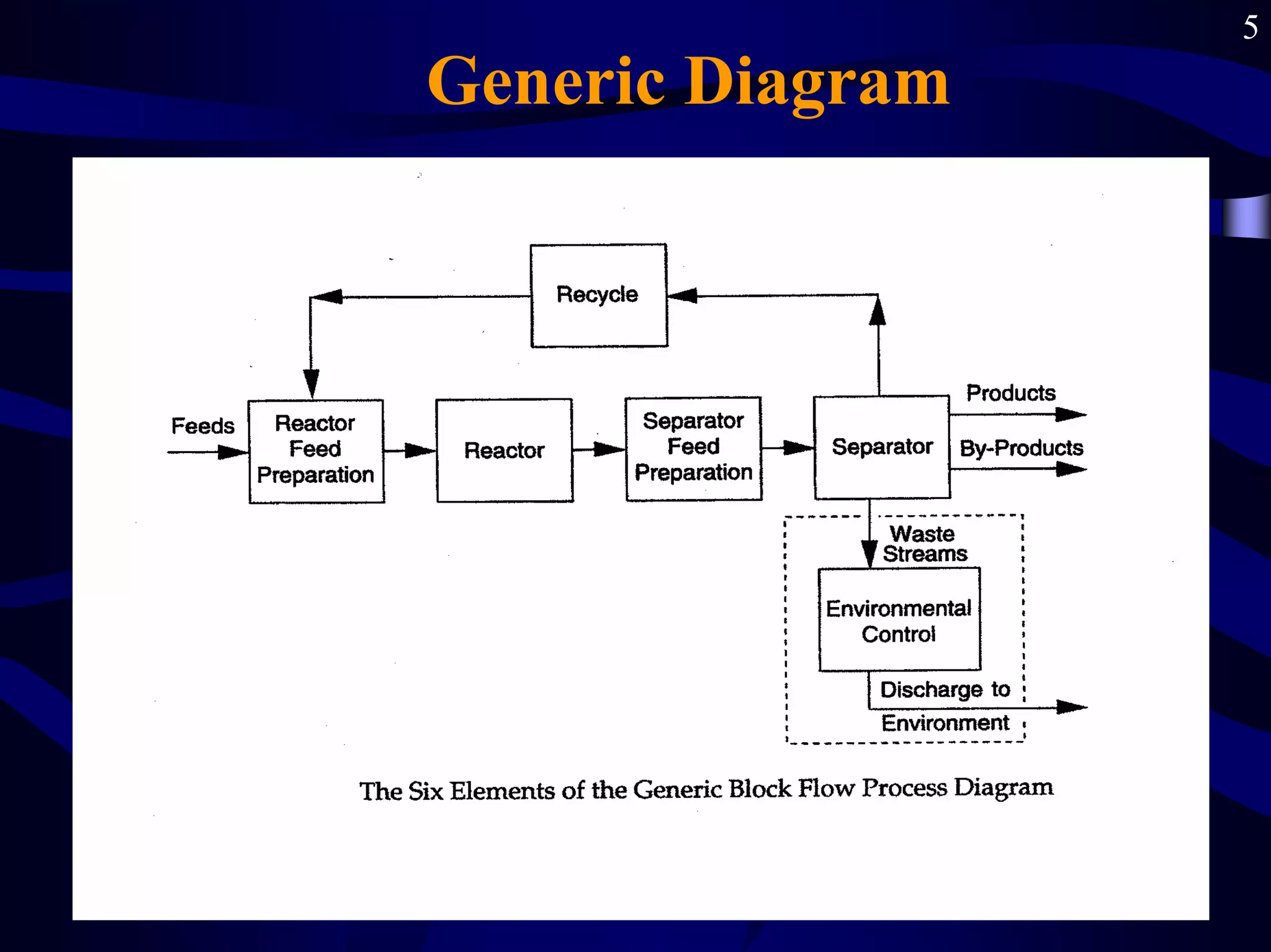
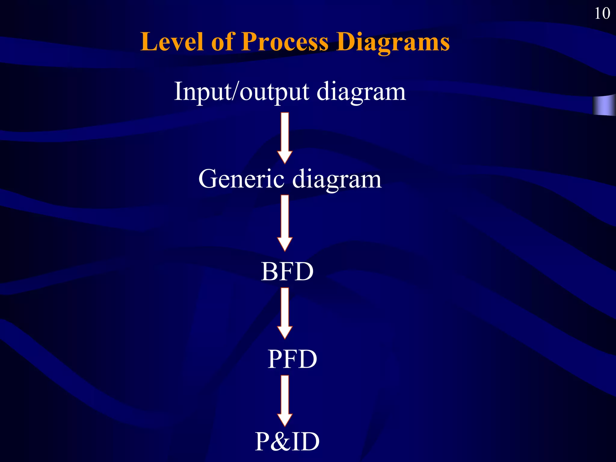
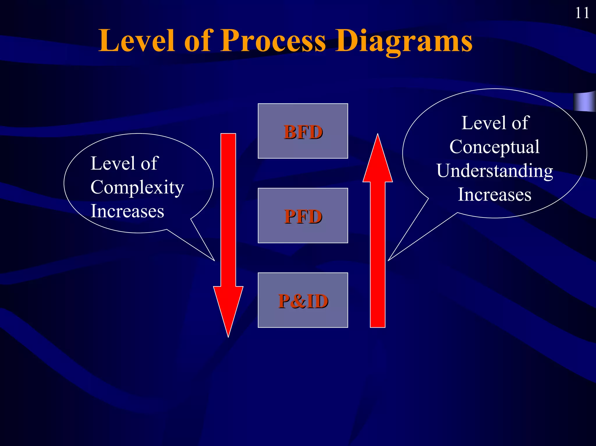
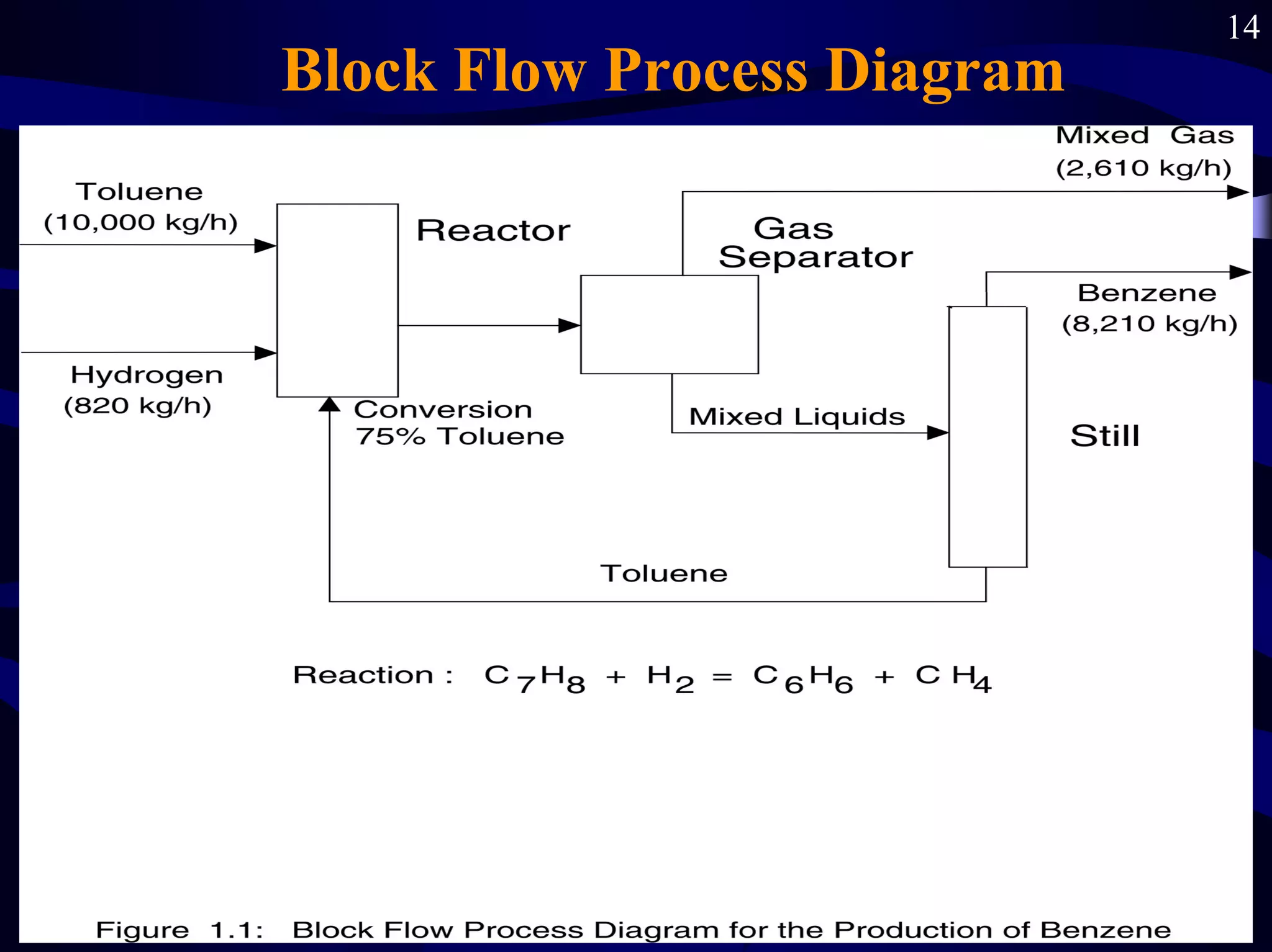
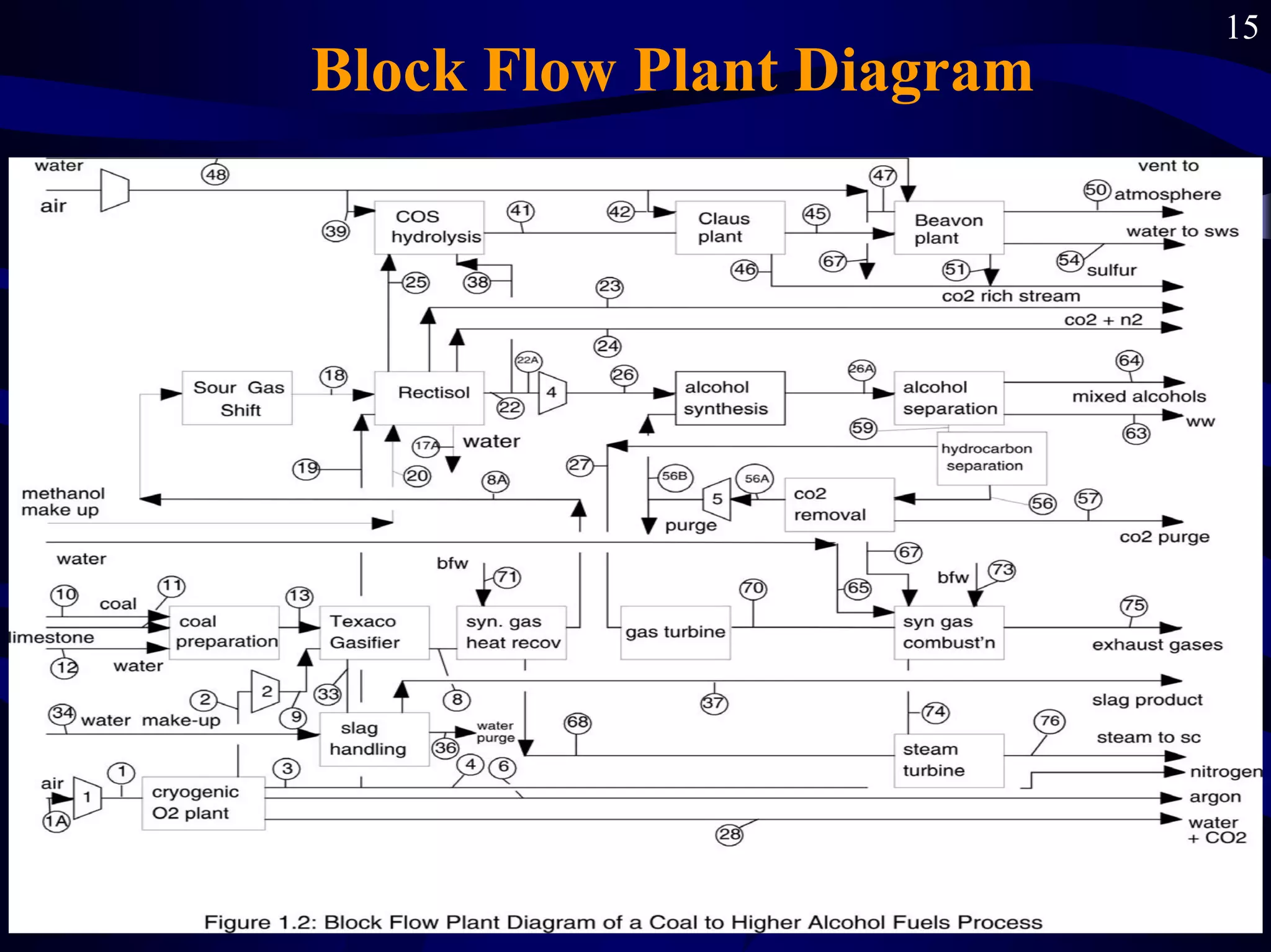
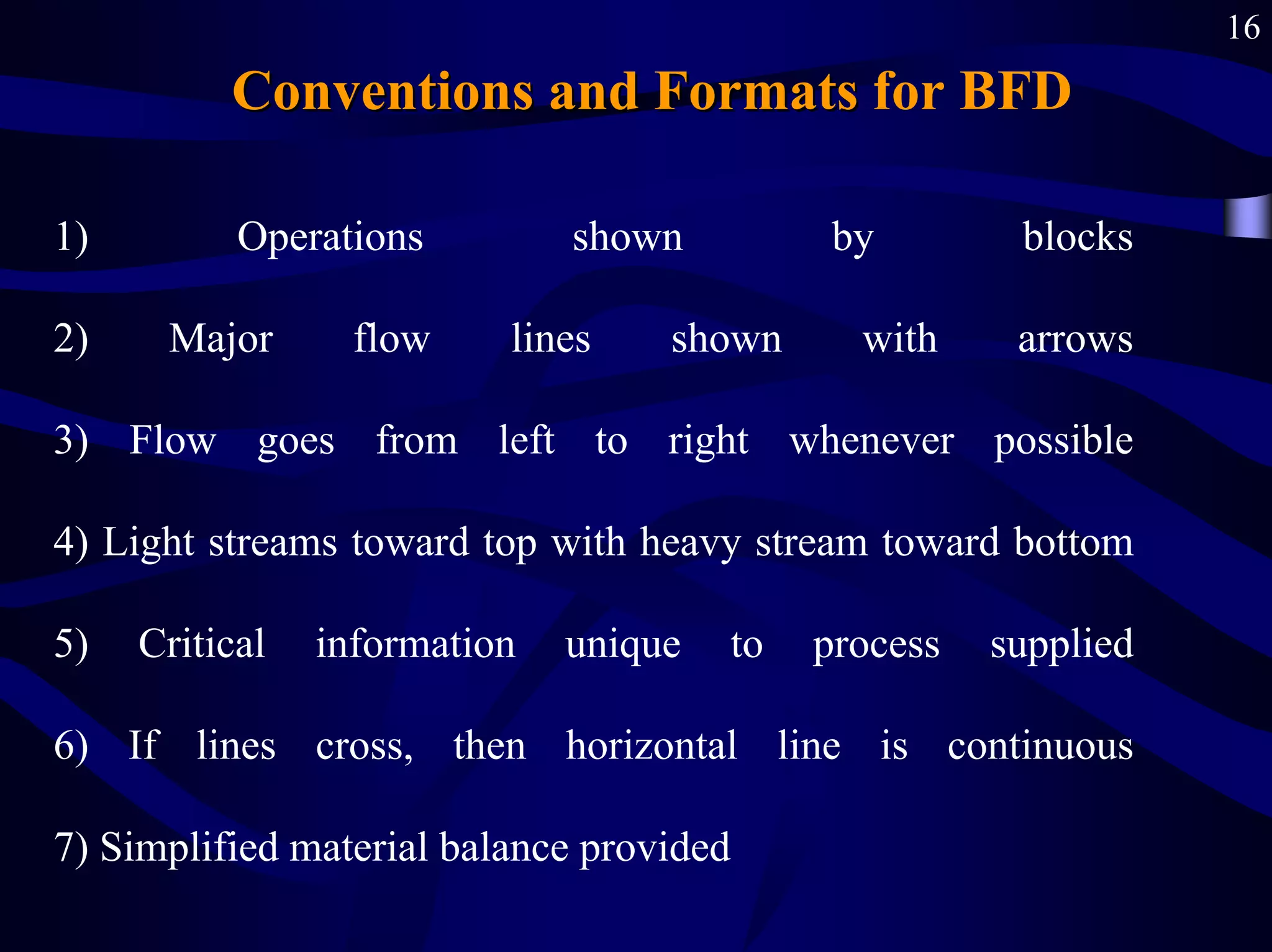


This document discusses different types of process diagrams used in chemical engineering, starting with the most basic and moving to more complex diagrams. It focuses on block flow diagrams (BFDs), explaining that BFDs break a process into basic elements like reactions and separations. BFDs provide an overall picture of a chemical process and are useful for orienting oneself and screening process alternatives. The document outlines conventions for BFDs, such as representing operations with blocks and showing major flows with arrows going left to right when possible. BFDs form the starting point for more detailed piping and instrumentation diagrams.


