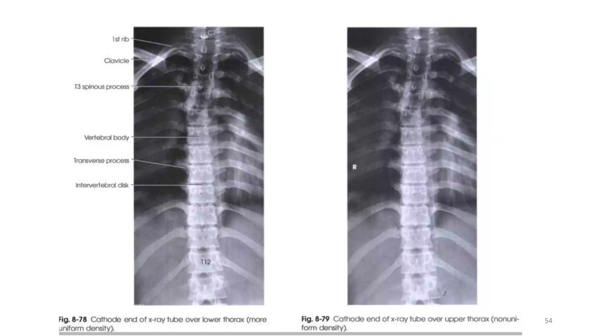
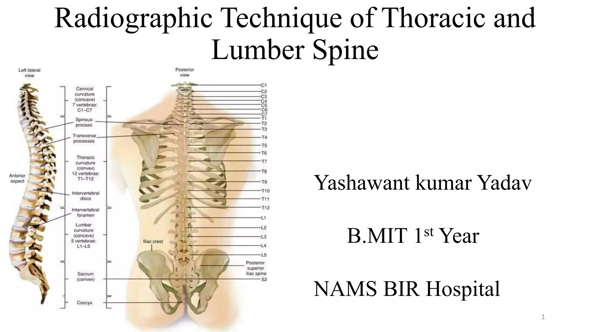
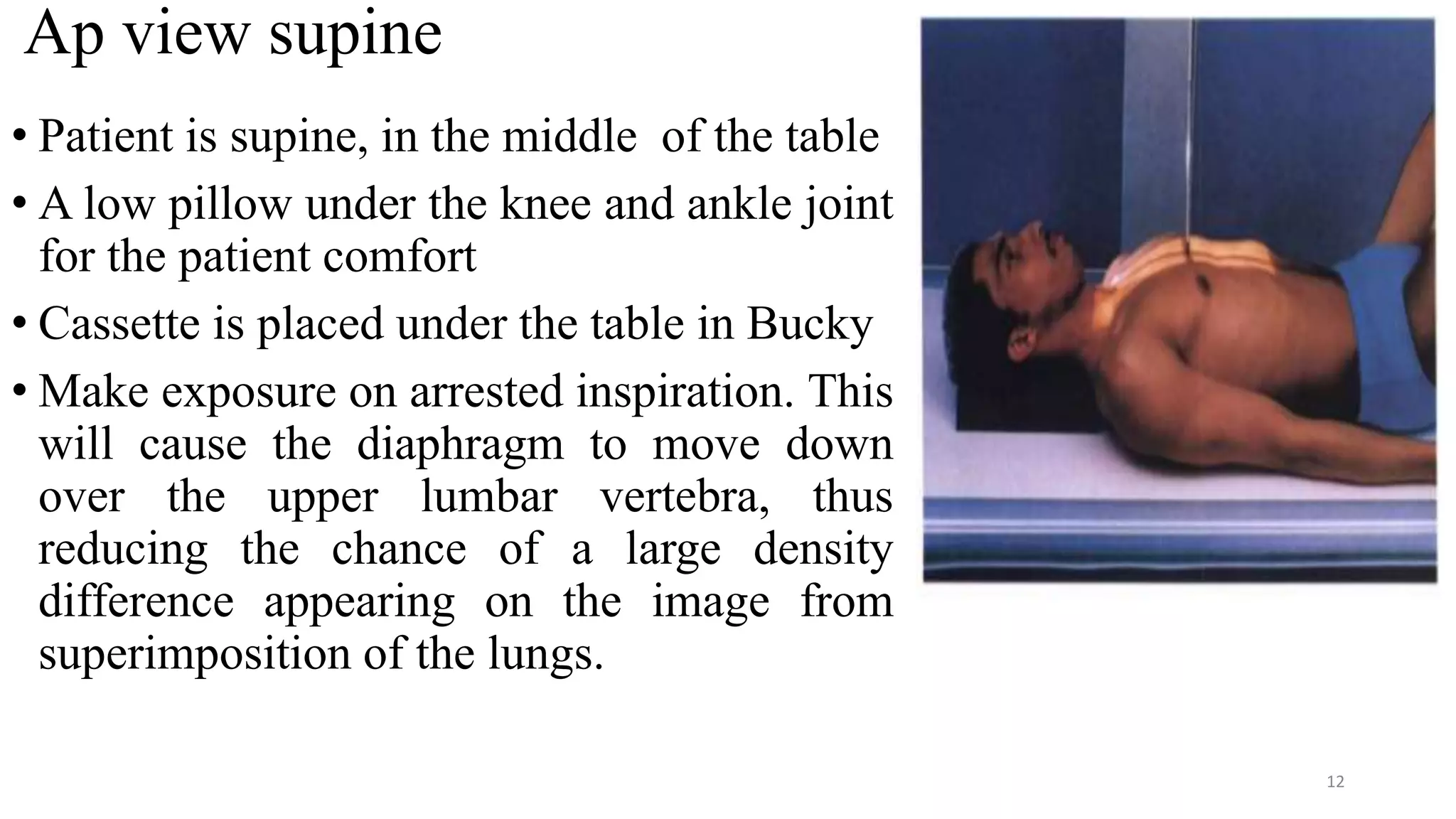
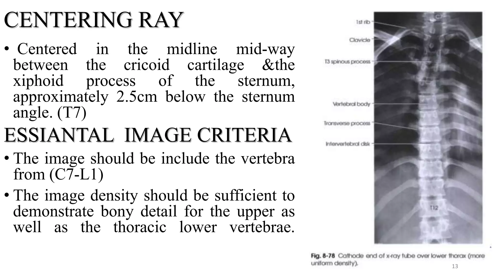
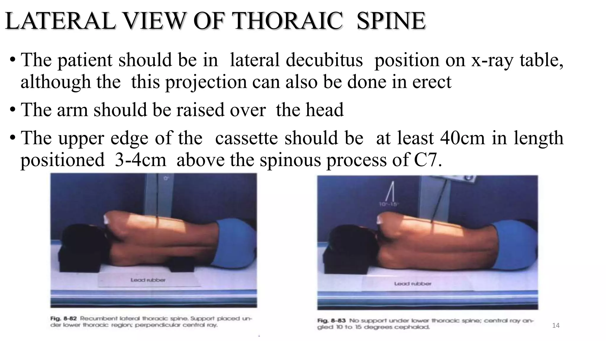
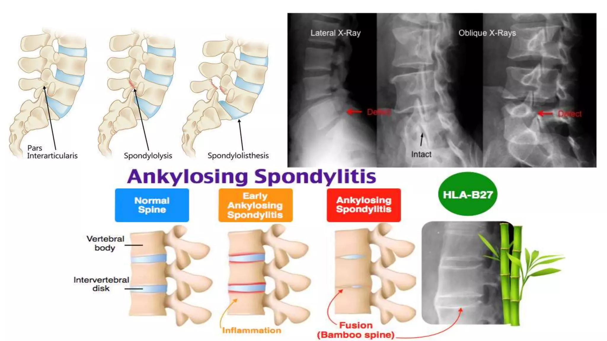
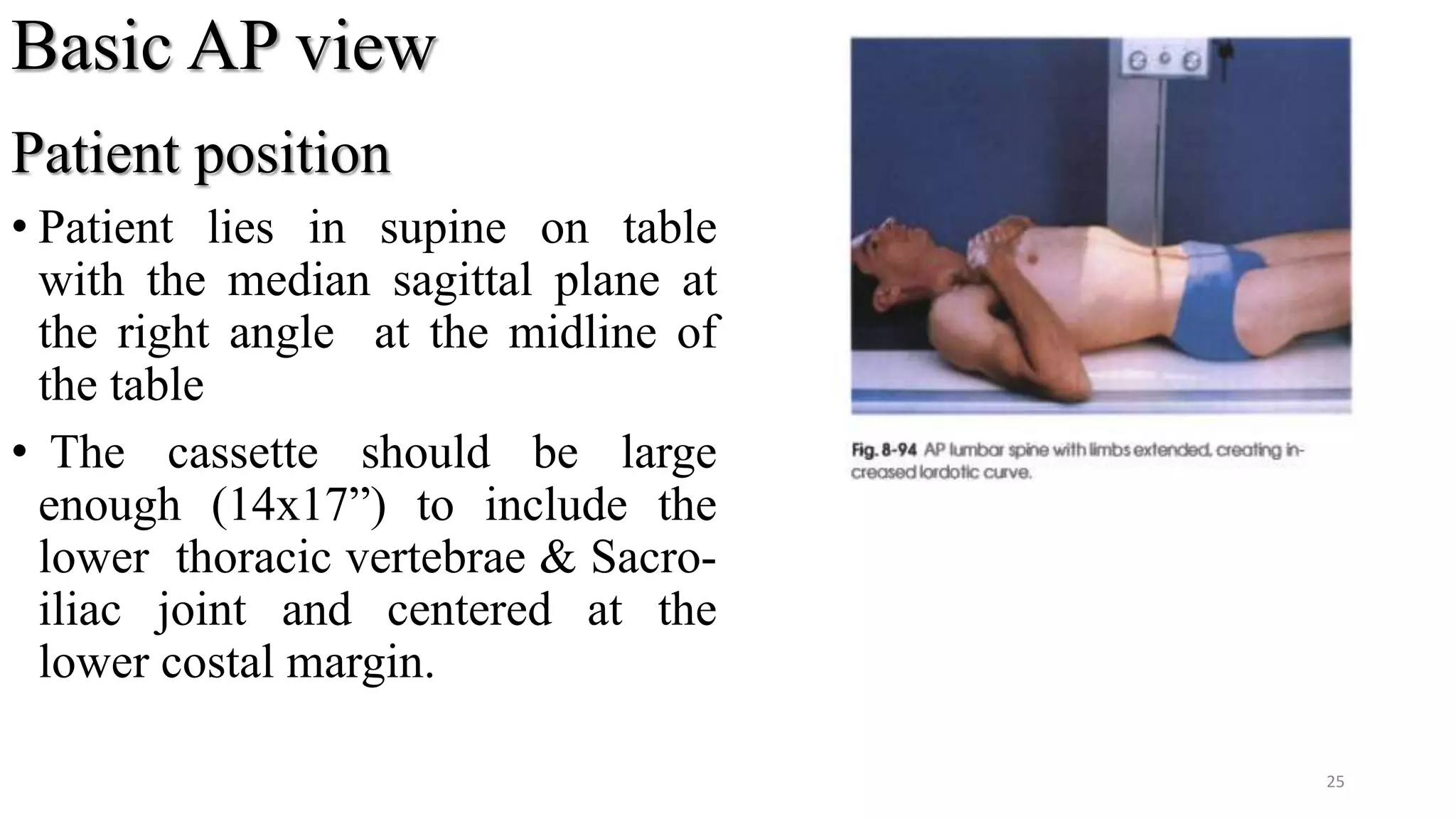
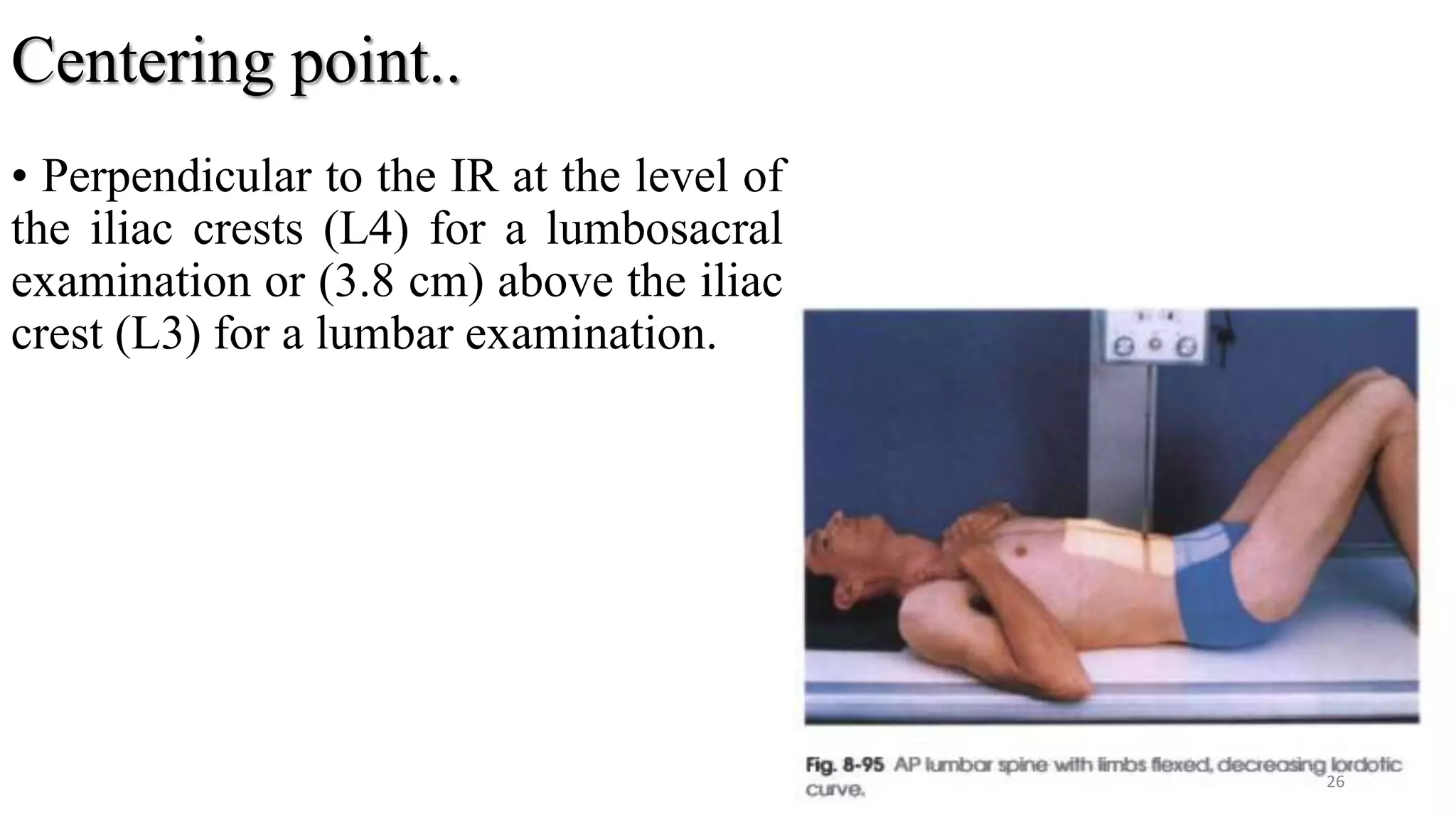
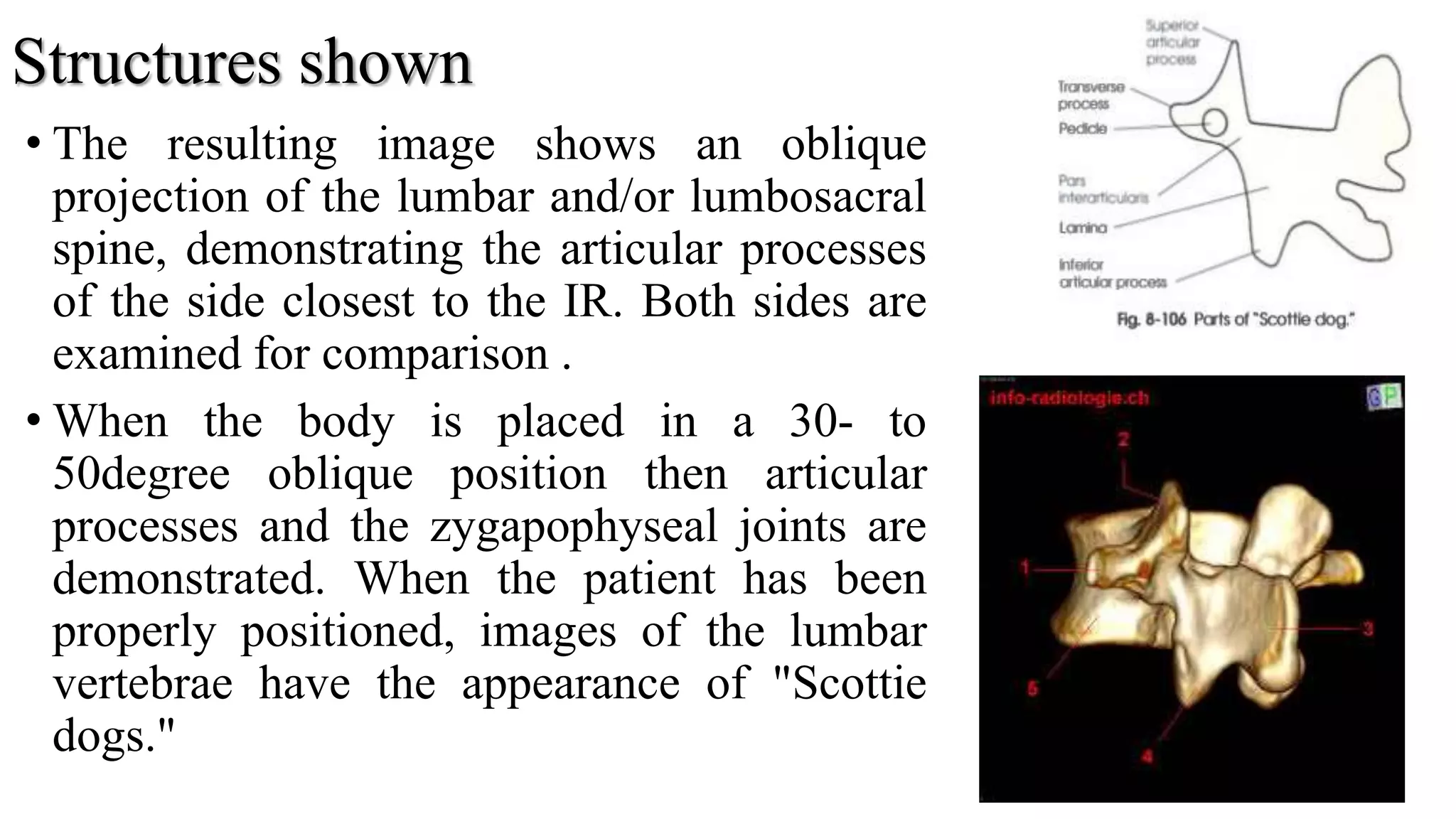
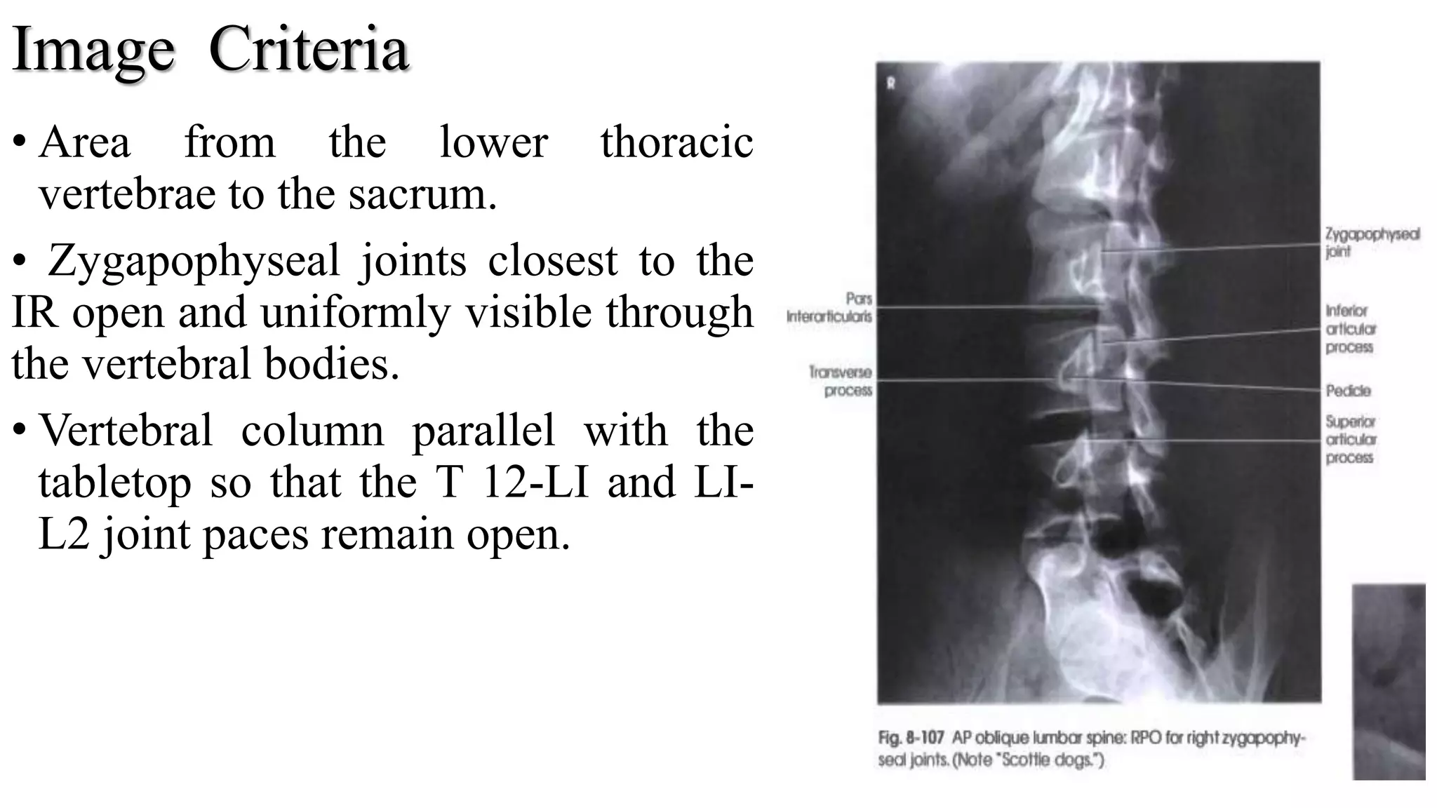
SlideShare a Scribd company logo
1 of 55
Radiographic Technique of Thoracic and
Lumber Spine
Yashawant kumar Yadav
B.MIT 1st Year
NAMS BIR Hospital
1
Overview
•Introduction
•Anatomy of spines
•Indications
•Recommended projections for T & L spine
•Summary
•references
2
Introduction
The vertebral column is commonly called the spine ,backbone
or spinal column ,is a complex succession of many bones.
It is a part of axial skeleton.
It provides a flexible supporting column of the trunk , head and
upper body to lower limbs.
The vertebral column houses the spinal canal, a cavity that
encloses and protects the spinal cord.
The vertebral column is composed of 33 bones which are given
below.
3
Contd..
Cervical vertebrae=7
Thoracic vertebrae=12
Lumber vertebrae=5
Sacrum vertebrae=5
Coccyx=4
4
Landmark of spines
T1 =25% of the time it is the most prominent, it does not rotate
as much as C7 when the head turns.(just below of cervical
vertebra)
T2-T3 =sternal or jugular notch
T3-T4 =sternal angle
T7 = inferior angle of scapula
T9-T10 =Xyphoid process
L3-L4 =umbilicus
5
Some Terminology
Lordosis:
The term lordosis ,meaning bent backward describes the normal
anterio-concavity of the cervical and lumber spine.
Kyphosis:
The meaning of kyphosis is described as abnormal or exaggerated
thoracic “Hump back "curvature with and increased convexity.
Scoliosis:
Abnormal of exaggerated in lateral curvature is called scoliosis.
6
Anatomy of T-Spine
• The thoracic spine is the longest region of the spine, and by some
measures it is also the most complex.
• Connecting with the cervical spine above and the lumbar spine below,
the thoracic spine runs from the base of the neck down to the abdomen.
• It is the only spinal region attached to the rib cage.
7
Contd..
• Consists of body, pedicle, lamina, spinous process, transverse process
and superior & inferior articular processes.
• Bodies of vertebrae increases in size fromT1 to T12
• The superior thoracic body resembles with the cervical body & inferior
with the lumbar body.
• They are distinguished by the presence of facets on the sides of the
bodies for articulation with the heads of the ribs, and facets on the
transverse processes of all, except the eleventh and twelfth, for
articulation with the tubercles of the ribs.
8
9
Indications
• Any cases of Trauma
• Fracture
• Dislocation
• Foreign body
• Kyphosis
• Subluxation
• Tumor
• Osteoarthritis
• osteoporosis etc.
10
Basic projections
For Trauma patient on Trolley:-
• Lateral supine with HB (basic)
• AP supine (basic)
Non traumatic pathology:-
• Lateral (basic )
• Supine (basic)
• Ap view erect/supine
• Lateral erect/lying lateral
• AP OR PA Oblique
Projection RAO and LAO or
RPO and LPO Upright and
recumbent positions.
11
Ap view supine
• Patient is supine, in the middle of the table
• A low pillow under the knee and ankle joint
for the patient comfort
• Cassette is placed under the table in Bucky
• Make exposure on arrested inspiration. This
will cause the diaphragm to move down
over the upper lumbar vertebra, thus
reducing the chance of a large density
difference appearing on the image from
superimposition of the lungs.
12
CENTERING RAY
• Centered in the midline mid-way
between the cricoid cartilage &the
xiphoid process of the sternum,
approximately 2.5cm below the sternum
angle. (T7)
ESSIANTAL IMAGE CRITERIA
• The image should be include the vertebra
from (C7-L1)
• The image density should be sufficient to
demonstrate bony detail for the upper as
well as the thoracic lower vertebrae.
13
LATERAL VIEW OF THORAIC SPINE
• The patient should be in lateral decubitus position on x-ray table,
although the this projection can also be done in erect
• The arm should be raised over the head
• The upper edge of the cassette should be at least 40cm in length
positioned 3-4cm above the spinous process of C7.
14
CENTERING RAY
• Center ray should be right angle of the axis of the thoracic vertebra.
This may required a caudal angulation.
• Centre 5 cm anterior to the spinous process of T6/7. This is usually
found just below the inferior angle of the scapula(assuming the arms
are raised), which is easily palpable.(clear)
ESSIANTAL IMAGE CRITERIA
• Upper two or three vertebra may not be visual due to super imposed by
shoulder.
15
Contd..
The posterior ribs should be superimposed, thus
indicating that the patient is not rotate too far
backward or forward
There should be clearly visualization of whole
spine(T1-T12)
16
AP OR PA OBLIQUE PROJECTION RAO and LAO or
RPO and LPO Upright and recumbent positions
• The thoracic zygapophyseal joints are examined using PA oblique
projections .
• Place the patient, standing or sitting upright, in a lateral position before
a vertical grid.
• Rotate the body 20 degrees anterior (PA oblique) or posterior (AP
oblique) so that the coronal plane form an angle of 70 degrees from the
plane of the IR.
• Adjust the patient's shoulder to lie in the same horizontal plane.
• Suspend the end of expiration.
17
Central ray
• Perpendicular to the IR exiting or entering the level of T7
18
Recumbent position
• Patient is Placed in a lateral recumbent position.
• Patient’s hips and knees is Flex to a comfortable position.
• For anterior (PA oblique) rotation, the lower arm is placed behind the
back and the upper arm forward with the hand on the table for support.
• Rotate the body slightly, either anteriorly or posteriorly 20 degrees, so
that the coronal plane forms an angle of 70 degrees with the horizontal.
• If needed, apply a compression band across the hips, but be careful not
to change the position.
• Suspend at the end of expiration.
19
Central ray:-
• Center the IR 11/2
to 2 inches (3.8-5 cm) above the shoulders to center it
at the level of T7.
20
ESSIANTAL IMAGE CRITERIA
• All twelve thoracic vertebrae .
• Zygapophyseal joints closest to the IR
on PA obliques and the joints farthest
from the film on AP obliques .
• Wide exposure latitude.
21
LUMBAR SPINE(L1-L5)
The lumbar spine consists of moveable
vertebrae numbered L1-L5.
The lumbar spine is designed to be incredibly
strong, protecting the highly sensitive spinal
cord and spinal nerve roots. At the same time, it
is highly flexible, providing for mobility in
many different planes including flexion,
extension, side bending, and rotation.
The first lumbar vertebra is level with the
anterior end of the ninth rib. This level is also
called the important transpyloric plane.
Lumber vertebrae doesn’t have facet .
22
Indications
• Low back pain
• Trauma
• Fracture
• Kyphosis
• Lordosis
• Scoliosis
• Spondylitis
• Spondylolysis
• Metastases
• Subluxation
• tumor 23
24
Basic AP view
Patient position
• Patient lies in supine on table
with the median sagittal plane at
the right angle at the midline of
the table
• The cassette should be large
enough (14x17”) to include the
lower thoracic vertebrae & Sacro-
iliac joint and centered at the
lower costal margin.
25
Centering point..
• Perpendicular to the IR at the level of
the iliac crests (L4) for a lumbosacral
examination or (3.8 cm) above the iliac
crest (L3) for a lumbar examination.
26
ESSIANTAL IMAGE CRITERIA
The image should include from the (T12)down, to include all of the
Sacro-iliac joint.
Rotation can be assessed by ensuring that the Sacro- iliac joints are
the equidistant from the spine.
The exposure used should produce a density such that bony detail can
be discerned throughout the region of interest.
27
28
LATERAL PROJECTION R or L position
The patient lies on either side on the Bucky table. If there is
any degree of scoliosis, then the most appropriate lateral position
will be such that the concavity of the curve is towards the
X-ray tube.
 The arms should be raised and resting on the pillow in front of
the patient’s head. The knees and hips are flexed for stability.
 The coronal plane running through the center of the spine
should coincide with, and be perpendicular to, the midline of
the Bucky.
 Non-opaque pads may be placed under the waist and knees,
as necessary, to bring the vertebral column parallel to the film.
29
Contd..
The cassette is centered at the level of the lower costal margin.
 The exposure should be made on arrested expiration.
 This projection can also be undertaken erect with the patient
standing or sitting.
30
Direction and centering of the X-ray beam
Direct the central ray at right-angles to the line of spinous
processes and towards a point 7.5 cm anterior to the third lumbar
spinous process at the level of the lower costal margin.
31
Essential image characteristics
• The image should include T12 downwards, to include the lumbar
sacral junction.
• Ideally, the projection will produce a clear view through the
center of the intervertebral disc space, with individual vertebral
end plates superimposed.
• The cortices at the posterior and anterior margins of the vertebral
body should also be superimposed.
• The imaging factors selected must produce an image density
sufficient for diagnosis from T12 to L5/S1, including the spinous
processes.
32
33
AP Oblique Projection RPO and LPO positions
• The patient turns from the supine position
toward the affected side approximately 45
degree to demonstrate the joints closest to the
IR (opposite the thoracic zygapophyseal
joints).
• Adjust the patient's body so that the long axis
of the patient is parallel with the long axis of
the radiographic table.
• Center the patient's spine to the midline of
the grid.
• Suspend at the end of expiration.
34
Central ray
• Enter 2 inches (5 cm) medial to
the elevated ASIS and 1-1/2
inches (3.8 cm) above the iliac
crest (L3).
• Center the IR to the central ray.
35
Structures shown
• The resulting image shows an oblique
projection of the lumbar and/or lumbosacral
spine, demonstrating the articular processes
of the side closest to the IR. Both sides are
examined for comparison .
• When the body is placed in a 30- to
50degree oblique position then articular
processes and the zygapophyseal joints are
demonstrated. When the patient has been
properly positioned, images of the lumbar
vertebrae have the appearance of "Scottie
dogs."
36
Image Criteria
• Area from the lower thoracic
vertebrae to the sacrum.
• Zygapophyseal joints closest to the
IR open and uniformly visible through
the vertebral bodies.
• Vertebral column parallel with the
tabletop so that the T 12-LI and LI-
L2 joint paces remain open.
37
PA Oblique Projection RAO and LAO positions
• Examine the patient in the upright or recumbent prone position. The
recumbent position generally used because it facilitates immobilization.
• However, the OID is increased, which can affect resolution.
• The joints farthest from the IR are demonstrated with the PA oblique
projection (opposite the thoracic zygapophyseal joints).
• From the prone position, have the patient turn to a semi-prone position
and support the body on the forearm and flexed knee.
• Center the IR at the level of L3.
• To demonstrate the lumbosacral joint, position the patient as described
above but center L5.
38
Central ray
• Perpendicular to enter the L3 (1
to ½ inches [2.5 to 3.8 cm]
above the crest of the ilium).
The central ray enter the
elevated ide approximately 2
inches (5 cm) lateral to the
palpable spinous process.
39
Structures shown
• The resulting image shows an oblique projection of the lumbar or
lumbosacral vertebrae, demonstrating the articular processes of the
side farther from the IR .
• The fifth lumbosacral joint is usually well demonstrated in oblique
position.
• When the body is placed in a 30- to 50degree oblique position and
the lumbar spine is radiographed, the articular processes and
zygapophyseal joints are demonstrated .
• When the patient has been properly positioned, image of the
lumbar vertebrae have the appearance of "Scottie dog .”
40
41
Evaluation Criteria
• Area from the lower thoracic
vertebrae to the sacrum.
• Zygapophyseal joints farthest from
the IR.
• When the joint is not well
demonstrated and the pedicle is quite
anterior on the vertebral body, the
patient is not rotated enough.
• When the joint is not well
demonstrated and the pedicle is quite
posterior on the vertebral body, the
patient is rotated too much. 42
Lateral Horizontal Beam
Patient’s preparation
• The trauma trolley is placed adjacent to the vertical Bucky.
• Adjust the position of the trolley so that the lower costal margin of the
patient coincides with the vertical central line of the Bucky and the
median sagittal plane is parallel to the cassette.
• The Bucky should be raised or lowered such that the patient’s mid-
coronal plane is coincident with the midline of the cassette within the
Bucky, along its long axis.
• If possible, the arms should be raised above the head.
43
44
Direction and centering of the X-ray beam
• Direct the horizontal central ray parallel to a line joining the anterior
superior iliac spines and towards a point 7.5cm anterior to the third
lumbar spinous process at the level of the lower costal margin.
Essential image characteristics
• Refer to lateral lumbar spine.
• Extreme care must be taken if using the automatic exposure control.
The chamber selected must be directly in line with the vertebrae,
otherwise an incorrect exposure will result.
45
Contd…
• If a manual exposure is selected, then a higher exposure will be required than with
a supine lateral. This is due to the effect of gravity on the internal organs, causing
them to lie either side of the spine.
46
Lateral Flexion and Extension
• Lateral projections in flexion and extension may be requested to
demonstrate mobility and stability of the lumbar vertebrae.
Patient preparation
• This projection may be performed supine, but it is most commonly
performed erect with the patient seated on a stool with either side
against the vertical Bucky.
• A seated position is preferred, since apparent flexion and extension of
the lumbar region is less likely to be due to movement of the hip joints
when using the erect position.
47
• The dorsal surface of the
trunk should be at right-angles
to the cassette and the
vertebral column parallel to
the cassette.
• For the first exposure the
patient leans forward, For the
second exposure the patient
then leans backward,
• The cassette is centered at
the level of the lower costal
margin, and the exposure is
made on arrested expiration.
48
Direction and centering of the X-ray beam
• Direct the central ray at right-angles to the
film and towards a point 7.5cm anterior to
the third lumbar spinous process at the level
of the lower costal margin.
Essential image characteristics
• Refer to lateral lumbar spine .
• All of the area of interest must be included
on both projections.
49
50
Exposure according to positions of T&L
Thoracic spine mAs KVp
AP/oblique 16-30-50 60-66
Lat 30-50 60-66
Lumber spine
AP/oblique 25-35 65-75
Lateral 30-40 70-80
51
References
•Clark’s 13th ed
•Merrill's
•web
52
53
54
Cricoid cartilages = ?
Auto tomography=?
55

More Related Content

What's hot

Shoulder radiography avinesh shrestha
Shoulder radiography avinesh shresthaShoulder radiography avinesh shrestha
Shoulder radiography avinesh shresthaAvinesh Shrestha
 
RADIOGRAPHIC VIEWS FOR HIP JOINT
RADIOGRAPHIC VIEWS FOR HIP JOINTRADIOGRAPHIC VIEWS FOR HIP JOINT
RADIOGRAPHIC VIEWS FOR HIP JOINTGanesan Yogananthem
 
Radiographic positioning of Upper limb (ELBOW & HUMERUS)
Radiographic positioning of Upper limb (ELBOW & HUMERUS)Radiographic positioning of Upper limb (ELBOW & HUMERUS)
Radiographic positioning of Upper limb (ELBOW & HUMERUS)Nasir Mohiudin
 
X ray c-spine
X ray c-spine X ray c-spine
X ray c-spine Rajaoct
 
RADIOGRAPHIC VIEWS OF ANKLE JOINT
RADIOGRAPHIC VIEWS OF ANKLE JOINTRADIOGRAPHIC VIEWS OF ANKLE JOINT
RADIOGRAPHIC VIEWS OF ANKLE JOINTGanesan Yogananthem
 
Radiographic positioning of humerus and shoulder
Radiographic positioning of humerus and shoulderRadiographic positioning of humerus and shoulder
Radiographic positioning of humerus and shouldershajitha khan
 
Upper extremity anatomy & positioning
Upper extremity anatomy & positioningUpper extremity anatomy & positioning
Upper extremity anatomy & positioningInfoUtilRT
 
Technique 1 Upper limbs 3
Technique 1 Upper limbs 3Technique 1 Upper limbs 3
Technique 1 Upper limbs 3Behzad Ommani
 
Radiography Positioning Spine
Radiography Positioning SpineRadiography Positioning Spine
Radiography Positioning SpineDeepak Prasath
 
Advanced radiographic positions for the lower extremities
Advanced radiographic positions for the lower extremitiesAdvanced radiographic positions for the lower extremities
Advanced radiographic positions for the lower extremitiesmr_koky
 
Pelvic radiographs
Pelvic radiographsPelvic radiographs
Pelvic radiographsJob Abutu
 
Shoulder girdle presentation
Shoulder girdle presentationShoulder girdle presentation
Shoulder girdle presentationEmmie Macabiog
 
Plain X-ray SKULL
Plain X-ray SKULLPlain X-ray SKULL
Plain X-ray SKULLSameer Peer
 

What's hot (20)

Shoulder radiography avinesh shrestha
Shoulder radiography avinesh shresthaShoulder radiography avinesh shrestha
Shoulder radiography avinesh shrestha
 
RADIOGRAPHIC VIEWS FOR HIP JOINT
RADIOGRAPHIC VIEWS FOR HIP JOINTRADIOGRAPHIC VIEWS FOR HIP JOINT
RADIOGRAPHIC VIEWS FOR HIP JOINT
 
Radiographic positioning of Upper limb (ELBOW & HUMERUS)
Radiographic positioning of Upper limb (ELBOW & HUMERUS)Radiographic positioning of Upper limb (ELBOW & HUMERUS)
Radiographic positioning of Upper limb (ELBOW & HUMERUS)
 
X ray c-spine
X ray c-spine X ray c-spine
X ray c-spine
 
Positioning of skull
Positioning of skullPositioning of skull
Positioning of skull
 
RADIOGRAPHIC VIEWS OF ANKLE JOINT
RADIOGRAPHIC VIEWS OF ANKLE JOINTRADIOGRAPHIC VIEWS OF ANKLE JOINT
RADIOGRAPHIC VIEWS OF ANKLE JOINT
 
Radiographic positioning of humerus and shoulder
Radiographic positioning of humerus and shoulderRadiographic positioning of humerus and shoulder
Radiographic positioning of humerus and shoulder
 
RADIOGRAPHY OF SPINE .pptx
RADIOGRAPHY OF SPINE .pptxRADIOGRAPHY OF SPINE .pptx
RADIOGRAPHY OF SPINE .pptx
 
Upper extremity anatomy & positioning
Upper extremity anatomy & positioningUpper extremity anatomy & positioning
Upper extremity anatomy & positioning
 
Upper limb
Upper limbUpper limb
Upper limb
 
Technique 1 Upper limbs 3
Technique 1 Upper limbs 3Technique 1 Upper limbs 3
Technique 1 Upper limbs 3
 
C spine positioning
C spine positioningC spine positioning
C spine positioning
 
Radiography Positioning Spine
Radiography Positioning SpineRadiography Positioning Spine
Radiography Positioning Spine
 
Various X-ray views of Knee Joint
Various X-ray views of Knee JointVarious X-ray views of Knee Joint
Various X-ray views of Knee Joint
 
Advanced radiographic positions for the lower extremities
Advanced radiographic positions for the lower extremitiesAdvanced radiographic positions for the lower extremities
Advanced radiographic positions for the lower extremities
 
Pelvic radiographs
Pelvic radiographsPelvic radiographs
Pelvic radiographs
 
Shoulder girdle presentation
Shoulder girdle presentationShoulder girdle presentation
Shoulder girdle presentation
 
Plain X-ray SKULL
Plain X-ray SKULLPlain X-ray SKULL
Plain X-ray SKULL
 
SHOULDER JOINT
SHOULDER JOINTSHOULDER JOINT
SHOULDER JOINT
 
Skull radiography
Skull radiography Skull radiography
Skull radiography
 

Similar to Presentation1.pptx thoraccic and lumber spine

ANATOMY AND POSITIONING OF KNEE.pptx
ANATOMY AND POSITIONING OF KNEE.pptxANATOMY AND POSITIONING OF KNEE.pptx
ANATOMY AND POSITIONING OF KNEE.pptxdypradio
 
(4-M) 301 - A Shoulder to Clavicle.pptx
(4-M) 301 - A  Shoulder to Clavicle.pptx(4-M) 301 - A  Shoulder to Clavicle.pptx
(4-M) 301 - A Shoulder to Clavicle.pptxShiennaRoseAnnManalo1
 
(4-M) 301 - A Shoulder to Clavicle.pptx
(4-M) 301 - A  Shoulder to Clavicle.pptx(4-M) 301 - A  Shoulder to Clavicle.pptx
(4-M) 301 - A Shoulder to Clavicle.pptxShiennaRoseAnnManalo1
 
RADIOGRAPHY OF CHEST AND SPINE
RADIOGRAPHY OF CHEST AND SPINERADIOGRAPHY OF CHEST AND SPINE
RADIOGRAPHY OF CHEST AND SPINEkunalj000
 
X ray of foot and ankle
X ray of foot and ankle X ray of foot and ankle
X ray of foot and ankle Sulav_56
 
Radiographic views of proximal femur and pelvis
Radiographic views of proximal femur and pelvisRadiographic views of proximal femur and pelvis
Radiographic views of proximal femur and pelvisChandan Prasad
 
Radiographic anatomy and views of c spine
Radiographic anatomy and views of c spineRadiographic anatomy and views of c spine
Radiographic anatomy and views of c spineChandan Prasad
 
Interpretation of Xrays of the spine.pptx
Interpretation of Xrays of the spine.pptxInterpretation of Xrays of the spine.pptx
Interpretation of Xrays of the spine.pptxVigny Tsamo
 
Technique 1 Upper limbs 2
Technique 1 Upper limbs 2Technique 1 Upper limbs 2
Technique 1 Upper limbs 2Behzad Ommani
 
Radiography clinical updates - session one
Radiography clinical updates - session one Radiography clinical updates - session one
Radiography clinical updates - session one menkantozz
 
Technique 1 Lower limbs 3
Technique 1 Lower limbs 3Technique 1 Lower limbs 3
Technique 1 Lower limbs 3Behzad Ommani
 
Dr. Javed Hassan Raza spine anatomy and biomechanics.pptx
Dr. Javed Hassan Raza spine anatomy and biomechanics.pptxDr. Javed Hassan Raza spine anatomy and biomechanics.pptx
Dr. Javed Hassan Raza spine anatomy and biomechanics.pptxAkmalZaib1
 
Spine_Radiography.pptx
Spine_Radiography.pptxSpine_Radiography.pptx
Spine_Radiography.pptxshyam sunder
 
[3] The Back and ANS.pptx
[3] The Back and ANS.pptx[3] The Back and ANS.pptx
[3] The Back and ANS.pptxDivinefavour12
 
X Ray and MRI of Knee Joint
X Ray and MRI of Knee JointX Ray and MRI of Knee Joint
X Ray and MRI of Knee JointGaurav Purohit
 

Similar to Presentation1.pptx thoraccic and lumber spine (20)

Oesophagus swallow
Oesophagus swallowOesophagus swallow
Oesophagus swallow
 
radiocapsule 8th may.pptx
radiocapsule 8th may.pptxradiocapsule 8th may.pptx
radiocapsule 8th may.pptx
 
ANATOMY AND POSITIONING OF KNEE.pptx
ANATOMY AND POSITIONING OF KNEE.pptxANATOMY AND POSITIONING OF KNEE.pptx
ANATOMY AND POSITIONING OF KNEE.pptx
 
(4-M) 301 - A Shoulder to Clavicle.pptx
(4-M) 301 - A  Shoulder to Clavicle.pptx(4-M) 301 - A  Shoulder to Clavicle.pptx
(4-M) 301 - A Shoulder to Clavicle.pptx
 
(4-M) 301 - A Shoulder to Clavicle.pptx
(4-M) 301 - A  Shoulder to Clavicle.pptx(4-M) 301 - A  Shoulder to Clavicle.pptx
(4-M) 301 - A Shoulder to Clavicle.pptx
 
X ray c-spine
X ray c-spineX ray c-spine
X ray c-spine
 
RADIOGRAPHY OF CHEST AND SPINE
RADIOGRAPHY OF CHEST AND SPINERADIOGRAPHY OF CHEST AND SPINE
RADIOGRAPHY OF CHEST AND SPINE
 
X ray of foot and ankle
X ray of foot and ankle X ray of foot and ankle
X ray of foot and ankle
 
Radiographic views of proximal femur and pelvis
Radiographic views of proximal femur and pelvisRadiographic views of proximal femur and pelvis
Radiographic views of proximal femur and pelvis
 
Radiographic anatomy and views of c spine
Radiographic anatomy and views of c spineRadiographic anatomy and views of c spine
Radiographic anatomy and views of c spine
 
Interpretation of Xrays of the spine.pptx
Interpretation of Xrays of the spine.pptxInterpretation of Xrays of the spine.pptx
Interpretation of Xrays of the spine.pptx
 
Technique 1 Upper limbs 2
Technique 1 Upper limbs 2Technique 1 Upper limbs 2
Technique 1 Upper limbs 2
 
Radiography clinical updates - session one
Radiography clinical updates - session one Radiography clinical updates - session one
Radiography clinical updates - session one
 
Technique 1 Lower limbs 3
Technique 1 Lower limbs 3Technique 1 Lower limbs 3
Technique 1 Lower limbs 3
 
Dr. Javed Hassan Raza spine anatomy and biomechanics.pptx
Dr. Javed Hassan Raza spine anatomy and biomechanics.pptxDr. Javed Hassan Raza spine anatomy and biomechanics.pptx
Dr. Javed Hassan Raza spine anatomy and biomechanics.pptx
 
Spine_Radiography.pptx
Spine_Radiography.pptxSpine_Radiography.pptx
Spine_Radiography.pptx
 
Seminar new
Seminar newSeminar new
Seminar new
 
Spine radiography
Spine radiographySpine radiography
Spine radiography
 
[3] The Back and ANS.pptx
[3] The Back and ANS.pptx[3] The Back and ANS.pptx
[3] The Back and ANS.pptx
 
X Ray and MRI of Knee Joint
X Ray and MRI of Knee JointX Ray and MRI of Knee Joint
X Ray and MRI of Knee Joint
 

More from Yashawant Yadav

Mr procedure of pelvis and hip joint
Mr procedure of pelvis and hip jointMr procedure of pelvis and hip joint
Mr procedure of pelvis and hip jointYashawant Yadav
 
Positron emission tomography pet scan and its applications
Positron emission tomography pet scan and its applicationsPositron emission tomography pet scan and its applications
Positron emission tomography pet scan and its applicationsYashawant Yadav
 
Application of ultrasound
Application of ultrasoundApplication of ultrasound
Application of ultrasoundYashawant Yadav
 
Ptc )percutaneous transhepatic cholangiography
Ptc )percutaneous transhepatic cholangiographyPtc )percutaneous transhepatic cholangiography
Ptc )percutaneous transhepatic cholangiographyYashawant Yadav
 
Ct coronary angiography edited 1st
Ct   coronary  angiography edited 1stCt   coronary  angiography edited 1st
Ct coronary angiography edited 1stYashawant Yadav
 
Mri spin echo pulse sequences its variations and
Mri spin echo pulse sequences its variations andMri spin echo pulse sequences its variations and
Mri spin echo pulse sequences its variations andYashawant Yadav
 
Technique of thoracic and lumber spine radiography
Technique  of thoracic and lumber spine radiographyTechnique  of thoracic and lumber spine radiography
Technique of thoracic and lumber spine radiographyYashawant Yadav
 
Digital breast tomosynthesis
Digital breast tomosynthesisDigital breast tomosynthesis
Digital breast tomosynthesisYashawant Yadav
 
Ptc )percutaneous transhepatic cholangiography
Ptc )percutaneous transhepatic cholangiographyPtc )percutaneous transhepatic cholangiography
Ptc )percutaneous transhepatic cholangiographyYashawant Yadav
 
High voltage transformer and high frequency generator
High voltage transformer and high frequency generatorHigh voltage transformer and high frequency generator
High voltage transformer and high frequency generatorYashawant Yadav
 
Radiological contrast media
Radiological contrast mediaRadiological contrast media
Radiological contrast mediaYashawant Yadav
 
Procedure of ercp and t tube cholangiography
Procedure of ercp and t tube cholangiographyProcedure of ercp and t tube cholangiography
Procedure of ercp and t tube cholangiographyYashawant Yadav
 
Technique of dental radiographic
Technique of dental radiographicTechnique of dental radiographic
Technique of dental radiographicYashawant Yadav
 
Presentation2.pptx technique chest 2
Presentation2.pptx technique chest 2Presentation2.pptx technique chest 2
Presentation2.pptx technique chest 2Yashawant Yadav
 
Image characteristics of x ray film
Image characteristics of x ray filmImage characteristics of x ray film
Image characteristics of x ray filmYashawant Yadav
 
Mammographic equipment and its advancement
Mammographic equipment and its advancementMammographic equipment and its advancement
Mammographic equipment and its advancementYashawant Yadav
 
Dacrocystography and sialography
Dacrocystography and sialographyDacrocystography and sialography
Dacrocystography and sialographyYashawant Yadav
 
Ct image quality artifacts and it remedy
Ct image quality artifacts and it remedyCt image quality artifacts and it remedy
Ct image quality artifacts and it remedyYashawant Yadav
 

More from Yashawant Yadav (20)

Mr procedure of pelvis and hip joint
Mr procedure of pelvis and hip jointMr procedure of pelvis and hip joint
Mr procedure of pelvis and hip joint
 
Positron emission tomography pet scan and its applications
Positron emission tomography pet scan and its applicationsPositron emission tomography pet scan and its applications
Positron emission tomography pet scan and its applications
 
Application of ultrasound
Application of ultrasoundApplication of ultrasound
Application of ultrasound
 
Ptc )percutaneous transhepatic cholangiography
Ptc )percutaneous transhepatic cholangiographyPtc )percutaneous transhepatic cholangiography
Ptc )percutaneous transhepatic cholangiography
 
Ct coronary angiography edited 1st
Ct   coronary  angiography edited 1stCt   coronary  angiography edited 1st
Ct coronary angiography edited 1st
 
Ct protocol for ivu
Ct protocol for ivuCt protocol for ivu
Ct protocol for ivu
 
Mri spin echo pulse sequences its variations and
Mri spin echo pulse sequences its variations andMri spin echo pulse sequences its variations and
Mri spin echo pulse sequences its variations and
 
Technique of thoracic and lumber spine radiography
Technique  of thoracic and lumber spine radiographyTechnique  of thoracic and lumber spine radiography
Technique of thoracic and lumber spine radiography
 
Digital breast tomosynthesis
Digital breast tomosynthesisDigital breast tomosynthesis
Digital breast tomosynthesis
 
Ptc )percutaneous transhepatic cholangiography
Ptc )percutaneous transhepatic cholangiographyPtc )percutaneous transhepatic cholangiography
Ptc )percutaneous transhepatic cholangiography
 
High voltage transformer and high frequency generator
High voltage transformer and high frequency generatorHigh voltage transformer and high frequency generator
High voltage transformer and high frequency generator
 
Radiological contrast media
Radiological contrast mediaRadiological contrast media
Radiological contrast media
 
Procedure of ercp and t tube cholangiography
Procedure of ercp and t tube cholangiographyProcedure of ercp and t tube cholangiography
Procedure of ercp and t tube cholangiography
 
Technique of dental radiographic
Technique of dental radiographicTechnique of dental radiographic
Technique of dental radiographic
 
Presentation2.pptx technique chest 2
Presentation2.pptx technique chest 2Presentation2.pptx technique chest 2
Presentation2.pptx technique chest 2
 
Image characteristics of x ray film
Image characteristics of x ray filmImage characteristics of x ray film
Image characteristics of x ray film
 
Procedure of upper gi
Procedure of upper giProcedure of upper gi
Procedure of upper gi
 
Mammographic equipment and its advancement
Mammographic equipment and its advancementMammographic equipment and its advancement
Mammographic equipment and its advancement
 
Dacrocystography and sialography
Dacrocystography and sialographyDacrocystography and sialography
Dacrocystography and sialography
 
Ct image quality artifacts and it remedy
Ct image quality artifacts and it remedyCt image quality artifacts and it remedy
Ct image quality artifacts and it remedy
 

Recently uploaded

Hybridoma Technology ( Production , Purification , and Application )
Hybridoma Technology  ( Production , Purification , and Application  ) Hybridoma Technology  ( Production , Purification , and Application  )
Hybridoma Technology ( Production , Purification , and Application ) Sakshi Ghasle
 
“Oh GOSH! Reflecting on Hackteria's Collaborative Practices in a Global Do-It...
“Oh GOSH! Reflecting on Hackteria's Collaborative Practices in a Global Do-It...“Oh GOSH! Reflecting on Hackteria's Collaborative Practices in a Global Do-It...
“Oh GOSH! Reflecting on Hackteria's Collaborative Practices in a Global Do-It...Marc Dusseiller Dusjagr
 
Paris 2024 Olympic Geographies - an activity
Paris 2024 Olympic Geographies - an activityParis 2024 Olympic Geographies - an activity
Paris 2024 Olympic Geographies - an activityGeoBlogs
 
Call Girls in Dwarka Mor Delhi Contact Us 9654467111
Call Girls in Dwarka Mor Delhi Contact Us 9654467111Call Girls in Dwarka Mor Delhi Contact Us 9654467111
Call Girls in Dwarka Mor Delhi Contact Us 9654467111Sapana Sha
 
Separation of Lanthanides/ Lanthanides and Actinides
Separation of Lanthanides/ Lanthanides and ActinidesSeparation of Lanthanides/ Lanthanides and Actinides
Separation of Lanthanides/ Lanthanides and ActinidesFatimaKhan178732
 
Concept of Vouching. B.Com(Hons) /B.Compdf
Concept of Vouching. B.Com(Hons) /B.CompdfConcept of Vouching. B.Com(Hons) /B.Compdf
Concept of Vouching. B.Com(Hons) /B.CompdfUmakantAnnand
 
KSHARA STURA .pptx---KSHARA KARMA THERAPY (CAUSTIC THERAPY)————IMP.OF KSHARA ...
KSHARA STURA .pptx---KSHARA KARMA THERAPY (CAUSTIC THERAPY)————IMP.OF KSHARA ...KSHARA STURA .pptx---KSHARA KARMA THERAPY (CAUSTIC THERAPY)————IMP.OF KSHARA ...
KSHARA STURA .pptx---KSHARA KARMA THERAPY (CAUSTIC THERAPY)————IMP.OF KSHARA ...M56BOOKSTORE PRODUCT/SERVICE
 
How to Make a Pirate ship Primary Education.pptx
How to Make a Pirate ship Primary Education.pptxHow to Make a Pirate ship Primary Education.pptx
How to Make a Pirate ship Primary Education.pptxmanuelaromero2013
 
Presiding Officer Training module 2024 lok sabha elections
Presiding Officer Training module 2024 lok sabha electionsPresiding Officer Training module 2024 lok sabha elections
Presiding Officer Training module 2024 lok sabha electionsanshu789521
 
Software Engineering Methodologies (overview)
Software Engineering Methodologies (overview)Software Engineering Methodologies (overview)
Software Engineering Methodologies (overview)eniolaolutunde
 
Enzyme, Pharmaceutical Aids, Miscellaneous Last Part of Chapter no 5th.pdf
Enzyme, Pharmaceutical Aids, Miscellaneous Last Part of Chapter no 5th.pdfEnzyme, Pharmaceutical Aids, Miscellaneous Last Part of Chapter no 5th.pdf
Enzyme, Pharmaceutical Aids, Miscellaneous Last Part of Chapter no 5th.pdfSumit Tiwari
 
The Most Excellent Way | 1 Corinthians 13
The Most Excellent Way | 1 Corinthians 13The Most Excellent Way | 1 Corinthians 13
The Most Excellent Way | 1 Corinthians 13Steve Thomason
 
Sanyam Choudhary Chemistry practical.pdf
Sanyam Choudhary Chemistry practical.pdfSanyam Choudhary Chemistry practical.pdf
Sanyam Choudhary Chemistry practical.pdfsanyamsingh5019
 
Solving Puzzles Benefits Everyone (English).pptx
Solving Puzzles Benefits Everyone (English).pptxSolving Puzzles Benefits Everyone (English).pptx
Solving Puzzles Benefits Everyone (English).pptxOH TEIK BIN
 
Contemporary philippine arts from the regions_PPT_Module_12 [Autosaved] (1).pptx
Contemporary philippine arts from the regions_PPT_Module_12 [Autosaved] (1).pptxContemporary philippine arts from the regions_PPT_Module_12 [Autosaved] (1).pptx
Contemporary philippine arts from the regions_PPT_Module_12 [Autosaved] (1).pptxRoyAbrique
 
Employee wellbeing at the workplace.pptx
Employee wellbeing at the workplace.pptxEmployee wellbeing at the workplace.pptx
Employee wellbeing at the workplace.pptxNirmalaLoungPoorunde1
 
A Critique of the Proposed National Education Policy Reform
A Critique of the Proposed National Education Policy ReformA Critique of the Proposed National Education Policy Reform
A Critique of the Proposed National Education Policy ReformChameera Dedduwage
 
Crayon Activity Handout For the Crayon A
Crayon Activity Handout For the Crayon ACrayon Activity Handout For the Crayon A
Crayon Activity Handout For the Crayon AUnboundStockton
 

Recently uploaded (20)

Hybridoma Technology ( Production , Purification , and Application )
Hybridoma Technology  ( Production , Purification , and Application  ) Hybridoma Technology  ( Production , Purification , and Application  )
Hybridoma Technology ( Production , Purification , and Application )
 
Staff of Color (SOC) Retention Efforts DDSD
Staff of Color (SOC) Retention Efforts DDSDStaff of Color (SOC) Retention Efforts DDSD
Staff of Color (SOC) Retention Efforts DDSD
 
“Oh GOSH! Reflecting on Hackteria's Collaborative Practices in a Global Do-It...
“Oh GOSH! Reflecting on Hackteria's Collaborative Practices in a Global Do-It...“Oh GOSH! Reflecting on Hackteria's Collaborative Practices in a Global Do-It...
“Oh GOSH! Reflecting on Hackteria's Collaborative Practices in a Global Do-It...
 
Paris 2024 Olympic Geographies - an activity
Paris 2024 Olympic Geographies - an activityParis 2024 Olympic Geographies - an activity
Paris 2024 Olympic Geographies - an activity
 
TataKelola dan KamSiber Kecerdasan Buatan v022.pdf
TataKelola dan KamSiber Kecerdasan Buatan v022.pdfTataKelola dan KamSiber Kecerdasan Buatan v022.pdf
TataKelola dan KamSiber Kecerdasan Buatan v022.pdf
 
Call Girls in Dwarka Mor Delhi Contact Us 9654467111
Call Girls in Dwarka Mor Delhi Contact Us 9654467111Call Girls in Dwarka Mor Delhi Contact Us 9654467111
Call Girls in Dwarka Mor Delhi Contact Us 9654467111
 
Separation of Lanthanides/ Lanthanides and Actinides
Separation of Lanthanides/ Lanthanides and ActinidesSeparation of Lanthanides/ Lanthanides and Actinides
Separation of Lanthanides/ Lanthanides and Actinides
 
Concept of Vouching. B.Com(Hons) /B.Compdf
Concept of Vouching. B.Com(Hons) /B.CompdfConcept of Vouching. B.Com(Hons) /B.Compdf
Concept of Vouching. B.Com(Hons) /B.Compdf
 
KSHARA STURA .pptx---KSHARA KARMA THERAPY (CAUSTIC THERAPY)————IMP.OF KSHARA ...
KSHARA STURA .pptx---KSHARA KARMA THERAPY (CAUSTIC THERAPY)————IMP.OF KSHARA ...KSHARA STURA .pptx---KSHARA KARMA THERAPY (CAUSTIC THERAPY)————IMP.OF KSHARA ...
KSHARA STURA .pptx---KSHARA KARMA THERAPY (CAUSTIC THERAPY)————IMP.OF KSHARA ...
 
How to Make a Pirate ship Primary Education.pptx
How to Make a Pirate ship Primary Education.pptxHow to Make a Pirate ship Primary Education.pptx
How to Make a Pirate ship Primary Education.pptx
 
Presiding Officer Training module 2024 lok sabha elections
Presiding Officer Training module 2024 lok sabha electionsPresiding Officer Training module 2024 lok sabha elections
Presiding Officer Training module 2024 lok sabha elections
 
Software Engineering Methodologies (overview)
Software Engineering Methodologies (overview)Software Engineering Methodologies (overview)
Software Engineering Methodologies (overview)
 
Enzyme, Pharmaceutical Aids, Miscellaneous Last Part of Chapter no 5th.pdf
Enzyme, Pharmaceutical Aids, Miscellaneous Last Part of Chapter no 5th.pdfEnzyme, Pharmaceutical Aids, Miscellaneous Last Part of Chapter no 5th.pdf
Enzyme, Pharmaceutical Aids, Miscellaneous Last Part of Chapter no 5th.pdf
 
The Most Excellent Way | 1 Corinthians 13
The Most Excellent Way | 1 Corinthians 13The Most Excellent Way | 1 Corinthians 13
The Most Excellent Way | 1 Corinthians 13
 
Sanyam Choudhary Chemistry practical.pdf
Sanyam Choudhary Chemistry practical.pdfSanyam Choudhary Chemistry practical.pdf
Sanyam Choudhary Chemistry practical.pdf
 
Solving Puzzles Benefits Everyone (English).pptx
Solving Puzzles Benefits Everyone (English).pptxSolving Puzzles Benefits Everyone (English).pptx
Solving Puzzles Benefits Everyone (English).pptx
 
Contemporary philippine arts from the regions_PPT_Module_12 [Autosaved] (1).pptx
Contemporary philippine arts from the regions_PPT_Module_12 [Autosaved] (1).pptxContemporary philippine arts from the regions_PPT_Module_12 [Autosaved] (1).pptx
Contemporary philippine arts from the regions_PPT_Module_12 [Autosaved] (1).pptx
 
Employee wellbeing at the workplace.pptx
Employee wellbeing at the workplace.pptxEmployee wellbeing at the workplace.pptx
Employee wellbeing at the workplace.pptx
 
A Critique of the Proposed National Education Policy Reform
A Critique of the Proposed National Education Policy ReformA Critique of the Proposed National Education Policy Reform
A Critique of the Proposed National Education Policy Reform
 
Crayon Activity Handout For the Crayon A
Crayon Activity Handout For the Crayon ACrayon Activity Handout For the Crayon A
Crayon Activity Handout For the Crayon A
 

Presentation1.pptx thoraccic and lumber spine

  • 1. Radiographic Technique of Thoracic and Lumber Spine Yashawant kumar Yadav B.MIT 1st Year NAMS BIR Hospital 1
  • 2. Overview •Introduction •Anatomy of spines •Indications •Recommended projections for T & L spine •Summary •references 2
  • 3. Introduction The vertebral column is commonly called the spine ,backbone or spinal column ,is a complex succession of many bones. It is a part of axial skeleton. It provides a flexible supporting column of the trunk , head and upper body to lower limbs. The vertebral column houses the spinal canal, a cavity that encloses and protects the spinal cord. The vertebral column is composed of 33 bones which are given below. 3
  • 4. Contd.. Cervical vertebrae=7 Thoracic vertebrae=12 Lumber vertebrae=5 Sacrum vertebrae=5 Coccyx=4 4
  • 5. Landmark of spines T1 =25% of the time it is the most prominent, it does not rotate as much as C7 when the head turns.(just below of cervical vertebra) T2-T3 =sternal or jugular notch T3-T4 =sternal angle T7 = inferior angle of scapula T9-T10 =Xyphoid process L3-L4 =umbilicus 5
  • 6. Some Terminology Lordosis: The term lordosis ,meaning bent backward describes the normal anterio-concavity of the cervical and lumber spine. Kyphosis: The meaning of kyphosis is described as abnormal or exaggerated thoracic “Hump back "curvature with and increased convexity. Scoliosis: Abnormal of exaggerated in lateral curvature is called scoliosis. 6
  • 7. Anatomy of T-Spine • The thoracic spine is the longest region of the spine, and by some measures it is also the most complex. • Connecting with the cervical spine above and the lumbar spine below, the thoracic spine runs from the base of the neck down to the abdomen. • It is the only spinal region attached to the rib cage. 7
  • 8. Contd.. • Consists of body, pedicle, lamina, spinous process, transverse process and superior & inferior articular processes. • Bodies of vertebrae increases in size fromT1 to T12 • The superior thoracic body resembles with the cervical body & inferior with the lumbar body. • They are distinguished by the presence of facets on the sides of the bodies for articulation with the heads of the ribs, and facets on the transverse processes of all, except the eleventh and twelfth, for articulation with the tubercles of the ribs. 8
  • 9. 9
  • 10. Indications • Any cases of Trauma • Fracture • Dislocation • Foreign body • Kyphosis • Subluxation • Tumor • Osteoarthritis • osteoporosis etc. 10
  • 11. Basic projections For Trauma patient on Trolley:- • Lateral supine with HB (basic) • AP supine (basic) Non traumatic pathology:- • Lateral (basic ) • Supine (basic) • Ap view erect/supine • Lateral erect/lying lateral • AP OR PA Oblique Projection RAO and LAO or RPO and LPO Upright and recumbent positions. 11
  • 12. Ap view supine • Patient is supine, in the middle of the table • A low pillow under the knee and ankle joint for the patient comfort • Cassette is placed under the table in Bucky • Make exposure on arrested inspiration. This will cause the diaphragm to move down over the upper lumbar vertebra, thus reducing the chance of a large density difference appearing on the image from superimposition of the lungs. 12
  • 13. CENTERING RAY • Centered in the midline mid-way between the cricoid cartilage &the xiphoid process of the sternum, approximately 2.5cm below the sternum angle. (T7) ESSIANTAL IMAGE CRITERIA • The image should be include the vertebra from (C7-L1) • The image density should be sufficient to demonstrate bony detail for the upper as well as the thoracic lower vertebrae. 13
  • 14. LATERAL VIEW OF THORAIC SPINE • The patient should be in lateral decubitus position on x-ray table, although the this projection can also be done in erect • The arm should be raised over the head • The upper edge of the cassette should be at least 40cm in length positioned 3-4cm above the spinous process of C7. 14
  • 15. CENTERING RAY • Center ray should be right angle of the axis of the thoracic vertebra. This may required a caudal angulation. • Centre 5 cm anterior to the spinous process of T6/7. This is usually found just below the inferior angle of the scapula(assuming the arms are raised), which is easily palpable.(clear) ESSIANTAL IMAGE CRITERIA • Upper two or three vertebra may not be visual due to super imposed by shoulder. 15
  • 16. Contd.. The posterior ribs should be superimposed, thus indicating that the patient is not rotate too far backward or forward There should be clearly visualization of whole spine(T1-T12) 16
  • 17. AP OR PA OBLIQUE PROJECTION RAO and LAO or RPO and LPO Upright and recumbent positions • The thoracic zygapophyseal joints are examined using PA oblique projections . • Place the patient, standing or sitting upright, in a lateral position before a vertical grid. • Rotate the body 20 degrees anterior (PA oblique) or posterior (AP oblique) so that the coronal plane form an angle of 70 degrees from the plane of the IR. • Adjust the patient's shoulder to lie in the same horizontal plane. • Suspend the end of expiration. 17
  • 18. Central ray • Perpendicular to the IR exiting or entering the level of T7 18
  • 19. Recumbent position • Patient is Placed in a lateral recumbent position. • Patient’s hips and knees is Flex to a comfortable position. • For anterior (PA oblique) rotation, the lower arm is placed behind the back and the upper arm forward with the hand on the table for support. • Rotate the body slightly, either anteriorly or posteriorly 20 degrees, so that the coronal plane forms an angle of 70 degrees with the horizontal. • If needed, apply a compression band across the hips, but be careful not to change the position. • Suspend at the end of expiration. 19
  • 20. Central ray:- • Center the IR 11/2 to 2 inches (3.8-5 cm) above the shoulders to center it at the level of T7. 20
  • 21. ESSIANTAL IMAGE CRITERIA • All twelve thoracic vertebrae . • Zygapophyseal joints closest to the IR on PA obliques and the joints farthest from the film on AP obliques . • Wide exposure latitude. 21
  • 22. LUMBAR SPINE(L1-L5) The lumbar spine consists of moveable vertebrae numbered L1-L5. The lumbar spine is designed to be incredibly strong, protecting the highly sensitive spinal cord and spinal nerve roots. At the same time, it is highly flexible, providing for mobility in many different planes including flexion, extension, side bending, and rotation. The first lumbar vertebra is level with the anterior end of the ninth rib. This level is also called the important transpyloric plane. Lumber vertebrae doesn’t have facet . 22
  • 23. Indications • Low back pain • Trauma • Fracture • Kyphosis • Lordosis • Scoliosis • Spondylitis • Spondylolysis • Metastases • Subluxation • tumor 23
  • 24. 24
  • 25. Basic AP view Patient position • Patient lies in supine on table with the median sagittal plane at the right angle at the midline of the table • The cassette should be large enough (14x17”) to include the lower thoracic vertebrae & Sacro- iliac joint and centered at the lower costal margin. 25
  • 26. Centering point.. • Perpendicular to the IR at the level of the iliac crests (L4) for a lumbosacral examination or (3.8 cm) above the iliac crest (L3) for a lumbar examination. 26
  • 27. ESSIANTAL IMAGE CRITERIA The image should include from the (T12)down, to include all of the Sacro-iliac joint. Rotation can be assessed by ensuring that the Sacro- iliac joints are the equidistant from the spine. The exposure used should produce a density such that bony detail can be discerned throughout the region of interest. 27
  • 28. 28
  • 29. LATERAL PROJECTION R or L position The patient lies on either side on the Bucky table. If there is any degree of scoliosis, then the most appropriate lateral position will be such that the concavity of the curve is towards the X-ray tube.  The arms should be raised and resting on the pillow in front of the patient’s head. The knees and hips are flexed for stability.  The coronal plane running through the center of the spine should coincide with, and be perpendicular to, the midline of the Bucky.  Non-opaque pads may be placed under the waist and knees, as necessary, to bring the vertebral column parallel to the film. 29
  • 30. Contd.. The cassette is centered at the level of the lower costal margin.  The exposure should be made on arrested expiration.  This projection can also be undertaken erect with the patient standing or sitting. 30
  • 31. Direction and centering of the X-ray beam Direct the central ray at right-angles to the line of spinous processes and towards a point 7.5 cm anterior to the third lumbar spinous process at the level of the lower costal margin. 31
  • 32. Essential image characteristics • The image should include T12 downwards, to include the lumbar sacral junction. • Ideally, the projection will produce a clear view through the center of the intervertebral disc space, with individual vertebral end plates superimposed. • The cortices at the posterior and anterior margins of the vertebral body should also be superimposed. • The imaging factors selected must produce an image density sufficient for diagnosis from T12 to L5/S1, including the spinous processes. 32
  • 33. 33
  • 34. AP Oblique Projection RPO and LPO positions • The patient turns from the supine position toward the affected side approximately 45 degree to demonstrate the joints closest to the IR (opposite the thoracic zygapophyseal joints). • Adjust the patient's body so that the long axis of the patient is parallel with the long axis of the radiographic table. • Center the patient's spine to the midline of the grid. • Suspend at the end of expiration. 34
  • 35. Central ray • Enter 2 inches (5 cm) medial to the elevated ASIS and 1-1/2 inches (3.8 cm) above the iliac crest (L3). • Center the IR to the central ray. 35
  • 36. Structures shown • The resulting image shows an oblique projection of the lumbar and/or lumbosacral spine, demonstrating the articular processes of the side closest to the IR. Both sides are examined for comparison . • When the body is placed in a 30- to 50degree oblique position then articular processes and the zygapophyseal joints are demonstrated. When the patient has been properly positioned, images of the lumbar vertebrae have the appearance of "Scottie dogs." 36
  • 37. Image Criteria • Area from the lower thoracic vertebrae to the sacrum. • Zygapophyseal joints closest to the IR open and uniformly visible through the vertebral bodies. • Vertebral column parallel with the tabletop so that the T 12-LI and LI- L2 joint paces remain open. 37
  • 38. PA Oblique Projection RAO and LAO positions • Examine the patient in the upright or recumbent prone position. The recumbent position generally used because it facilitates immobilization. • However, the OID is increased, which can affect resolution. • The joints farthest from the IR are demonstrated with the PA oblique projection (opposite the thoracic zygapophyseal joints). • From the prone position, have the patient turn to a semi-prone position and support the body on the forearm and flexed knee. • Center the IR at the level of L3. • To demonstrate the lumbosacral joint, position the patient as described above but center L5. 38
  • 39. Central ray • Perpendicular to enter the L3 (1 to ½ inches [2.5 to 3.8 cm] above the crest of the ilium). The central ray enter the elevated ide approximately 2 inches (5 cm) lateral to the palpable spinous process. 39
  • 40. Structures shown • The resulting image shows an oblique projection of the lumbar or lumbosacral vertebrae, demonstrating the articular processes of the side farther from the IR . • The fifth lumbosacral joint is usually well demonstrated in oblique position. • When the body is placed in a 30- to 50degree oblique position and the lumbar spine is radiographed, the articular processes and zygapophyseal joints are demonstrated . • When the patient has been properly positioned, image of the lumbar vertebrae have the appearance of "Scottie dog .” 40
  • 41. 41
  • 42. Evaluation Criteria • Area from the lower thoracic vertebrae to the sacrum. • Zygapophyseal joints farthest from the IR. • When the joint is not well demonstrated and the pedicle is quite anterior on the vertebral body, the patient is not rotated enough. • When the joint is not well demonstrated and the pedicle is quite posterior on the vertebral body, the patient is rotated too much. 42
  • 43. Lateral Horizontal Beam Patient’s preparation • The trauma trolley is placed adjacent to the vertical Bucky. • Adjust the position of the trolley so that the lower costal margin of the patient coincides with the vertical central line of the Bucky and the median sagittal plane is parallel to the cassette. • The Bucky should be raised or lowered such that the patient’s mid- coronal plane is coincident with the midline of the cassette within the Bucky, along its long axis. • If possible, the arms should be raised above the head. 43
  • 44. 44
  • 45. Direction and centering of the X-ray beam • Direct the horizontal central ray parallel to a line joining the anterior superior iliac spines and towards a point 7.5cm anterior to the third lumbar spinous process at the level of the lower costal margin. Essential image characteristics • Refer to lateral lumbar spine. • Extreme care must be taken if using the automatic exposure control. The chamber selected must be directly in line with the vertebrae, otherwise an incorrect exposure will result. 45
  • 46. Contd… • If a manual exposure is selected, then a higher exposure will be required than with a supine lateral. This is due to the effect of gravity on the internal organs, causing them to lie either side of the spine. 46
  • 47. Lateral Flexion and Extension • Lateral projections in flexion and extension may be requested to demonstrate mobility and stability of the lumbar vertebrae. Patient preparation • This projection may be performed supine, but it is most commonly performed erect with the patient seated on a stool with either side against the vertical Bucky. • A seated position is preferred, since apparent flexion and extension of the lumbar region is less likely to be due to movement of the hip joints when using the erect position. 47
  • 48. • The dorsal surface of the trunk should be at right-angles to the cassette and the vertebral column parallel to the cassette. • For the first exposure the patient leans forward, For the second exposure the patient then leans backward, • The cassette is centered at the level of the lower costal margin, and the exposure is made on arrested expiration. 48
  • 49. Direction and centering of the X-ray beam • Direct the central ray at right-angles to the film and towards a point 7.5cm anterior to the third lumbar spinous process at the level of the lower costal margin. Essential image characteristics • Refer to lateral lumbar spine . • All of the area of interest must be included on both projections. 49
  • 50. 50
  • 51. Exposure according to positions of T&L Thoracic spine mAs KVp AP/oblique 16-30-50 60-66 Lat 30-50 60-66 Lumber spine AP/oblique 25-35 65-75 Lateral 30-40 70-80 51
  • 53. 53
  • 54. 54
  • 55. Cricoid cartilages = ? Auto tomography=? 55