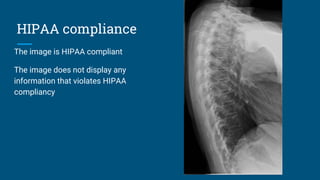
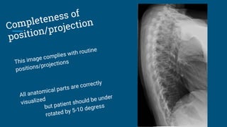
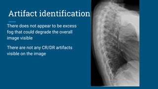
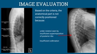
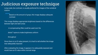
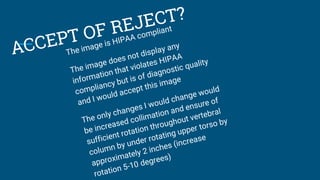
Thoracic spine (lateral)
Kaleigh taylor
HIPAA compliance
The image is HIPAA compliant
The image does not display any
information that violates HIPAA
compliancy
Marker and patient ID
There does not appear to be any side marker visualized in
the image
The technologist’s initials are not on the image
Since there is not a side marker present, it is not placed
correctly on the image
marker should be placed on the anterior surface of patient
There are not any markers superimposed on pertinent
anatomy
Additional side markers are not used
A marker indicating whether the patient was supine or
erect should be present
An arrow pointing to specific area of interest could be
used as well
Marker and patient ID
Since there is no marker present, I am only to
imagine this image is displayed correctly because a
left lateral position is what is normally done
All markers should be placed on the anterior
surface of the patient for lateral projections
Therefore, there should be a left side marker
along with the technologist’s initials on this
image
L
KT
Radiation hygiene
Proper beam restriction requires there be at least
three sides of collimation visible
this image complies with acceptable beam
restriction as there are three sides visible
Gonadal shielding should be used when the patient’s
gonads are within 5 cm of the primary beam
there is evidence to indicate appropriate use of
shielding because there is collimation on the
side closest to the gonads although there is
not a shield seen on the image
Artifact identification
No preventable physical artifacts are
visualized on this image
No body parts are superimposed where they
should not be
Hospital paraphernalia is not present on the
image
Patient clothing/belongings are not seen on
the image
There does not appear to be any indwelling
artifacts/foreign bodies present
Artifact identification
There does not appear to be excess
fog that could degrade the overall
image visible
There are not any CR/DR artifacts
visible on the image
Image sharpness
“Gross” voluntary motion is not seen in the image
Bony trabeculae is seen
A breathing technique is used to blur our rib and lung
markings and improve visualization of the vertebrae
Excessive quantum mottle is not visible on the image
There does not appear to be evidence of double exposure
present
Grids should be used when body parts measure greater than
10 cm
Grid lines, grid artifact and/or grid cut-off is not visible in the
image
A reciprocating/oscillating or high frequency grid was
most likely used for the image
Image sharpness
Size distortion is minimal due to the OID
between the spine of the patient and the
image receptor
The CR should enter the level of T7
off-centering is >1 cm so shape
distortion is visible
Accurate part positioning
The part is adequately aligned with the longitudinal axis of
the imaging media
The part is not accurately centered to the image media
Patient is slightly posterior and patient’s upper
torso should be moved anteriorly about 2
inches
The CR is not centered within 1 cm of the anatomical part
CR is distal to wanted area for centering
The CR is adequately aligned with the image media
The CR’s alignment conforms to an accepted IR exposure
field recognition template/field
Evidence of three sided collimation
Accurate part positioning
PATIENT POSITIONING FOR LATERAL T-
SPINE:
Patient positioned in lateral recumbent/erect position
Knees flexed for recumbent position
Arms abducted evenly to 90 degree angles in front of
body
Align posterior half of thorax to CR and midline of IR
Ensure entire spine is parallel to table by placing a
sponge under lower portion of thoracic spine
Ensure there is no rotation of shoulders or pelvis
CR perpendicular to long axis of thoracic spine directed
to T7 (7-8 inches below jugular notch)
Accurate part positioning
EVALUATION CRITERIA FOR LATERAL T-
SPINE:
Vertebral bodies, intervertebral joints and intervertebral
foramina visualized
T1-T3 will not be clearly seen
Intervertebral disk spaces open
No rotation indicated by superimposition of posterior
aspects of vertebral bodies
No rotation indicated by less than ½ inch of space
between posterior ribs
Collimation to area of interest
IMAGE EVALUATION
Based on the criteria, the
anatomical part is not
correctly positioned
because:
under rotation seen by
insufficient superimposition
of posterior ribs
Insufficient collimation
Judicious exposure technique
The most radiolucent structure visible on the
image is the soft tissue and the lung field
The most radiopaque structures visible is the
bony cortex of the vertebral bodies
Judicious exposure technique
Long scale, low contrast, is usually preferred for images of the vertebral
column
Based on the amount of grays, this image displays adequate
contrast
This image displays appropriate brightness based on the differences
between light and dark areas
A compensating filter could be used over the
distal T-spine to make brightness uniform
throughout
Since there is no EI value present, it is hard to tell whether the image
was adequately exposed
After evaluating the image, it appears it is adequately exposed and
would have an EI value within normal range
References
Eurich, Matthew. "Normal Radiographic Anatomy of the Thoracic Spine."
MyPACS.net. MyPACS, 8 Mar. 2017. Web. 06 Apr. 2017.
Bontrager, K. L., & Lampignano, J. (2013). Textbook of Radiographic Positioning
and Related Anatomy (8th ed.). Elsevier Health Sciences.
McQuillen-Martensen, K. (2015). Radiographic image analysis (4th ed.). St. Louis,
MO: Elsevier Saunders.

Lateral t spine kaleigh

  • 1.
  • 2.
    HIPAA compliance The imageis HIPAA compliant The image does not display any information that violates HIPAA compliancy
  • 3.
    Marker and patientID There does not appear to be any side marker visualized in the image The technologist’s initials are not on the image Since there is not a side marker present, it is not placed correctly on the image marker should be placed on the anterior surface of patient There are not any markers superimposed on pertinent anatomy Additional side markers are not used A marker indicating whether the patient was supine or erect should be present An arrow pointing to specific area of interest could be used as well
  • 4.
    Marker and patientID Since there is no marker present, I am only to imagine this image is displayed correctly because a left lateral position is what is normally done All markers should be placed on the anterior surface of the patient for lateral projections Therefore, there should be a left side marker along with the technologist’s initials on this image L KT
  • 5.
    Radiation hygiene Proper beamrestriction requires there be at least three sides of collimation visible this image complies with acceptable beam restriction as there are three sides visible Gonadal shielding should be used when the patient’s gonads are within 5 cm of the primary beam there is evidence to indicate appropriate use of shielding because there is collimation on the side closest to the gonads although there is not a shield seen on the image
  • 8.
    Artifact identification No preventablephysical artifacts are visualized on this image No body parts are superimposed where they should not be Hospital paraphernalia is not present on the image Patient clothing/belongings are not seen on the image There does not appear to be any indwelling artifacts/foreign bodies present
  • 9.
    Artifact identification There doesnot appear to be excess fog that could degrade the overall image visible There are not any CR/DR artifacts visible on the image
  • 10.
    Image sharpness “Gross” voluntarymotion is not seen in the image Bony trabeculae is seen A breathing technique is used to blur our rib and lung markings and improve visualization of the vertebrae Excessive quantum mottle is not visible on the image There does not appear to be evidence of double exposure present Grids should be used when body parts measure greater than 10 cm Grid lines, grid artifact and/or grid cut-off is not visible in the image A reciprocating/oscillating or high frequency grid was most likely used for the image
  • 11.
    Image sharpness Size distortionis minimal due to the OID between the spine of the patient and the image receptor The CR should enter the level of T7 off-centering is >1 cm so shape distortion is visible
  • 12.
    Accurate part positioning Thepart is adequately aligned with the longitudinal axis of the imaging media The part is not accurately centered to the image media Patient is slightly posterior and patient’s upper torso should be moved anteriorly about 2 inches The CR is not centered within 1 cm of the anatomical part CR is distal to wanted area for centering The CR is adequately aligned with the image media The CR’s alignment conforms to an accepted IR exposure field recognition template/field Evidence of three sided collimation
  • 13.
    Accurate part positioning PATIENTPOSITIONING FOR LATERAL T- SPINE: Patient positioned in lateral recumbent/erect position Knees flexed for recumbent position Arms abducted evenly to 90 degree angles in front of body Align posterior half of thorax to CR and midline of IR Ensure entire spine is parallel to table by placing a sponge under lower portion of thoracic spine Ensure there is no rotation of shoulders or pelvis CR perpendicular to long axis of thoracic spine directed to T7 (7-8 inches below jugular notch)
  • 14.
    Accurate part positioning EVALUATIONCRITERIA FOR LATERAL T- SPINE: Vertebral bodies, intervertebral joints and intervertebral foramina visualized T1-T3 will not be clearly seen Intervertebral disk spaces open No rotation indicated by superimposition of posterior aspects of vertebral bodies No rotation indicated by less than ½ inch of space between posterior ribs Collimation to area of interest
  • 15.
    IMAGE EVALUATION Based onthe criteria, the anatomical part is not correctly positioned because: under rotation seen by insufficient superimposition of posterior ribs Insufficient collimation
  • 16.
    Judicious exposure technique Themost radiolucent structure visible on the image is the soft tissue and the lung field The most radiopaque structures visible is the bony cortex of the vertebral bodies
  • 17.
    Judicious exposure technique Longscale, low contrast, is usually preferred for images of the vertebral column Based on the amount of grays, this image displays adequate contrast This image displays appropriate brightness based on the differences between light and dark areas A compensating filter could be used over the distal T-spine to make brightness uniform throughout Since there is no EI value present, it is hard to tell whether the image was adequately exposed After evaluating the image, it appears it is adequately exposed and would have an EI value within normal range
  • 19.
    References Eurich, Matthew. "NormalRadiographic Anatomy of the Thoracic Spine." MyPACS.net. MyPACS, 8 Mar. 2017. Web. 06 Apr. 2017. Bontrager, K. L., & Lampignano, J. (2013). Textbook of Radiographic Positioning and Related Anatomy (8th ed.). Elsevier Health Sciences. McQuillen-Martensen, K. (2015). Radiographic image analysis (4th ed.). St. Louis, MO: Elsevier Saunders.