Download to read offline


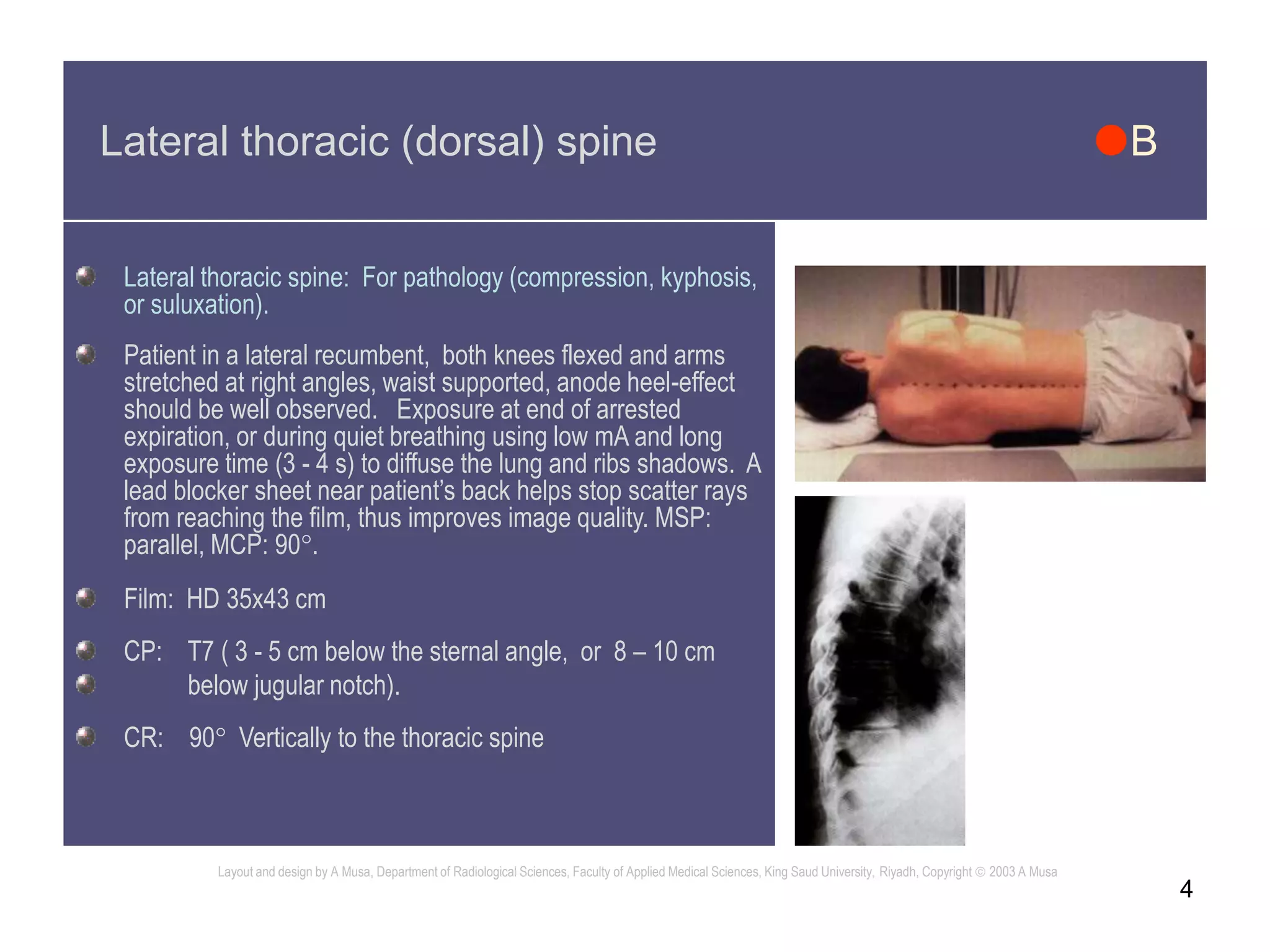


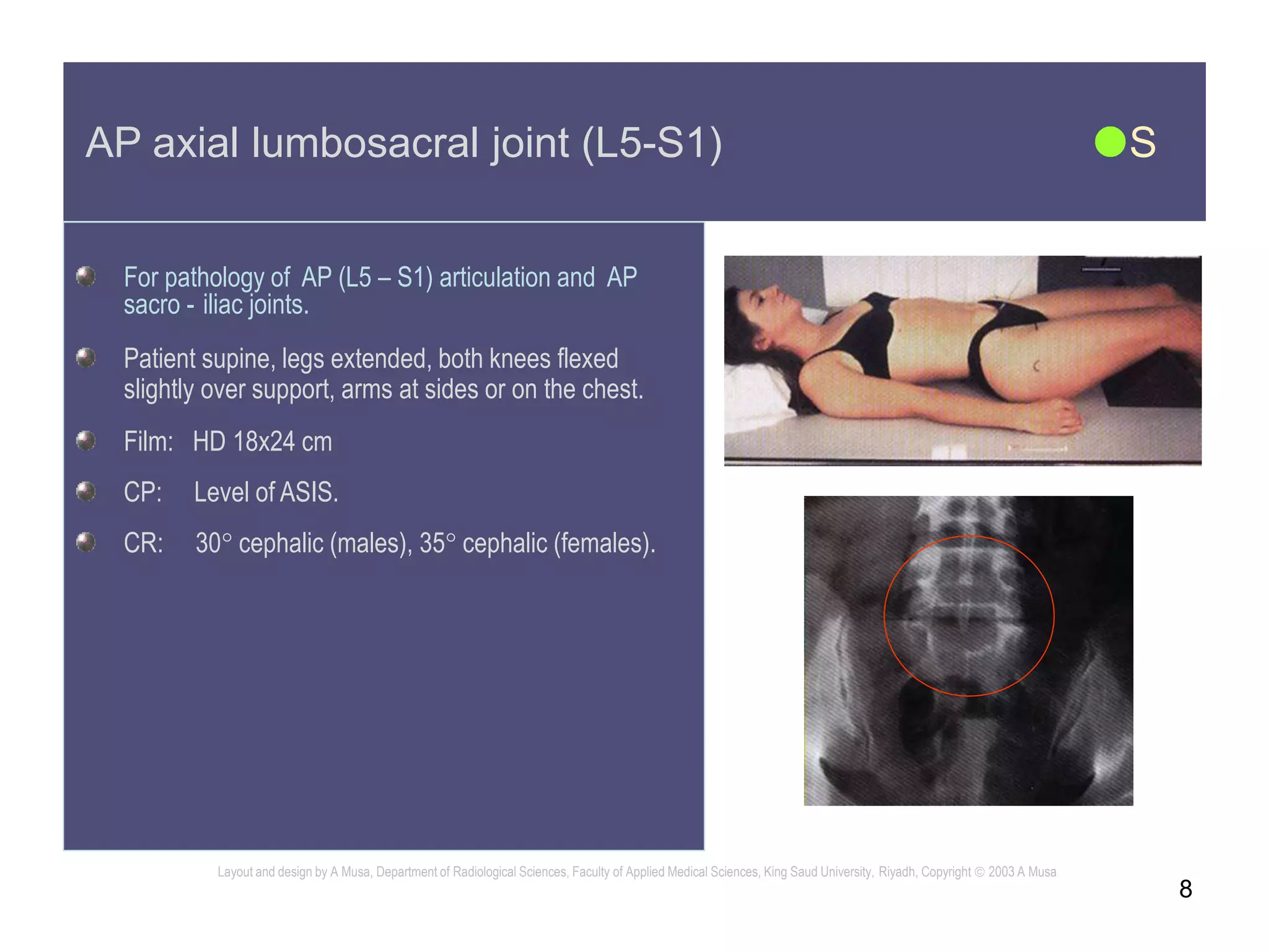


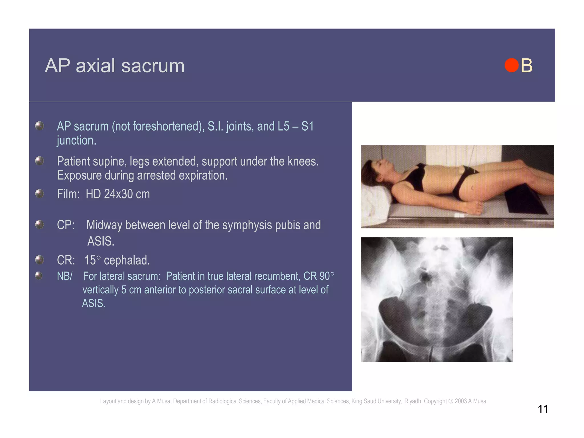


The document provides instructions for various spine radiographic projections including patient positioning, equipment settings, and exposure factors. It describes the AP, lateral, and oblique views of the thoracic and lumbar spine, sacrum, and coccyx. Optimal positioning aims to properly demonstrate anatomy while reducing scatter and improving image quality. Exposure settings range from 80-100 kVp and 7-100 mAs depending on the projection. The document aims to support high quality spine radiography and minimize radiation dose to patients.


![RADIOGRAPHIC_IMAGING_OF_THE_ABDOMEN[1].docx](https://cdn.slidesharecdn.com/ss_thumbnails/radiographicimagingoftheabdomen1-250705135117-4a4a689a-thumbnail.jpg?width=640&height=640&fit=bounds)


