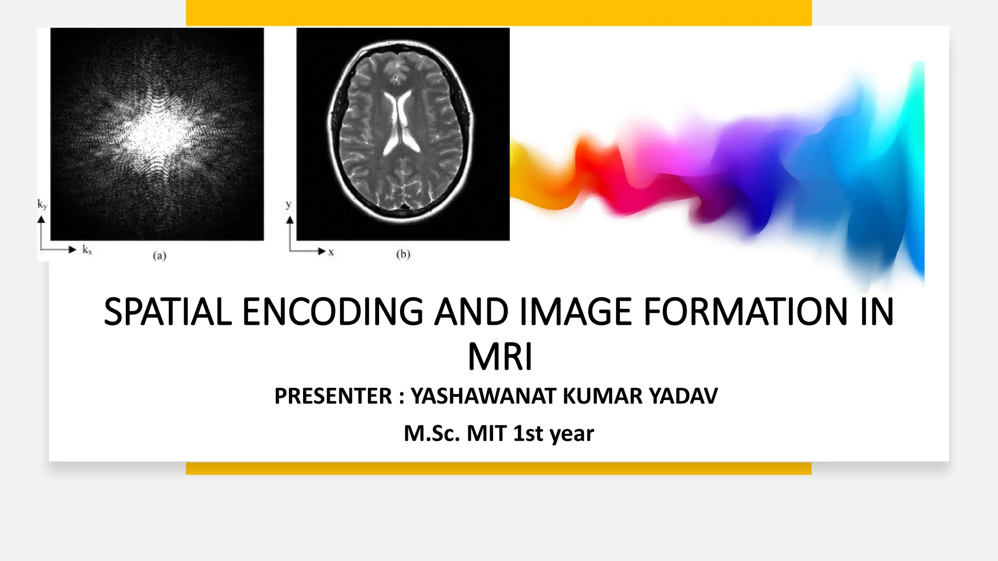
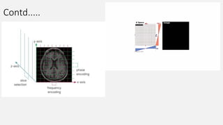
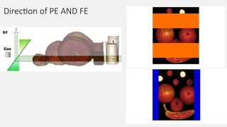
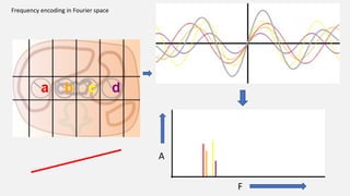
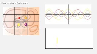
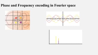
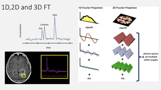
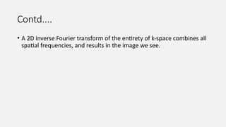
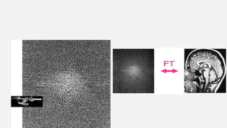
SPATIAL ENCODING AND IMAGE FORMATION IN
MRI
PRESENTER : YASHAWANAT KUMAR YADAV
M.Sc. MIT 1st year
Structure
• Introduction to MR Images.
• Signal formation in MRI
• Signal encoding in MRI
• K - SPACE
• Image Formation
• Summary
• References
1. Cryosection image
2. MRI image
3 CT image
4. USG image
5. SPECT image
6. Pet image
1. 2. 3
.
5. 6.
4.
MR Images
• Is it different than the other imaging modalities ?? (yes/no)
MODALITIES X RAY CT SCAN MRI NM(PET/SPECT) USG
RADIATION IONIZING IONIZING NON IONIZING IONIZING NON
IONIZING(SOUN
D WAVES)
DETECTORS YES, YES COILS DETECTORS PIEZOELECTRIC
CRYSTALS
SIGNAL
FORMATION
ELECTRIONIC ELECTRONIC ELECTRONIC ELECTRONIC ELECTRONIC
ADC
FOURIER TRANSFORMATION
INVERSE FOURIER TRANSFORMATION
DIGITAL IMAGE
SIGNAL FORMATION IN MRI
Contd....
• It should be stressed here that understanding image formation in MRI is
neither simple nor obvious and most people struggle to conceptualize it.
• An understanding of the image-formation process is helpful for obtaining the
optimum diagnostic information from an examination, modifying or creating
new protocols, recognizing common image artefacts and taking measures to
overcome or avoid them.
• It will also help as a basis for understanding the pulse sequences considered
and beyond.
• It is not just theory.
• It is the heart and soul of MRI.
Signal ??
It is a Radio wave that is emitted by the excited protons.
Why Radio waves are used in MRI?
Radio wave have very wide range of frequency spectrum and it is divided In to
total 9 bands.(ELF-EHF)(3Hz -------- 300GHz).
Larmor equation state the processional frequency of hydrogen protons at
different strength of magnetic field.
Highest Larmor frequency needed for MR imaging falls inside the Radio
frequency range.
SIGNAL TO IMAGE PROCESS At 1T 42.57MHz
At 1.5T 63.85MHz
At 3T 127.71MHz
Radio wave
• It's an electromagnetic wave , means it can
travel in both magnetic field and electric field
without getting affected by Either of magnetic
or electric field .
• It is not ionizing in nature .
• It can travel as same speed as light
• Wavelength of radio-waves are from few
millimeters to up-to the several
KM's. Wavelength of a radio wave at 30 Hz
is 10,000 kilometers,
Signal
• A purely sinusoidal signal or waveform has
three basic properties: amplitude, frequency
and phase.
1. Amplitude describes how large the signal
is, measured in volts or arbitrary ‘signal
units.
2. Frequency, measured in hertz (Hz),
describes how rapidly in time the
instantaneous magnitude of the wave is
changing: 1 Hz equals one cycle or
rotation per second.
3. Phase describes the instantaneous position
within the cyclic variation in terms of an
angle. It is measured in degrees or radians,
and can vary from 0 to 360.
SIGNAL TO IMAGE PROCESS
This signal alone is insufficient to produce an image of a patient lying within the
magnet bore because we would have no way of assigning parts of the signal to
where in the patient they originated.
To achieve this localization, we now need to introduce the concept of magnetic
field gradients, or in short ‘gradients’.
Gradients performs the spatial localization of signal generated from the selected
slice in-to the k space .
Now the most complicated and important steps begins for image formation.
Contd...
Gradients
• GRADIENTS COILS
• SPATIAL ENCODING OF MR SIGNAL ( Drs. Lauterbur and Mansfield
discovered)
1. Slice selection
2. Phase encoding
3. Frequency encoding
• Spatial encoding relies on successively applying magnetic field gradients.
SLICE SELECTION GRADIENT
LARMOR EQUATION
Slice selection
•The first step of spatial encoding consists in
selecting the slice plane. ​
•To do this, a magnetic field gradient, the Slice
Selection Gradient (GSS), is
applied perpendicular to the desired
slice plane.​
•The selected slice is always orthogonal
(perpendicular) to the gradient applied. ​
•So, far we have assumed the application
of GSS in the z axis, along the patient, giving a
trans -axial or transverse slice.
Contd....
CONTD....
• If we use Gx as a slice-select gradient we get a
sagittal slice.
• For a coronal slice we use Gy
• The designer RF pulse contains a narrow range of
frequencies of RF, centered about the Larmor
frequency.
• Oblique and double oblique slices can be created
using combinations of Gx , Gy and Gz
42.57 MHz
42.56 MHz
42.58 MHz
RF OF 42.57MHz
Contd....
The spins are all in
phase shortly after
their stimulation.
Frequency encoding
• Gradients mildly distort the main
magnetic field in a predictable
pattern, causing the resonance
frequency to vary as a function of
position.
• Frequency-encoding may be used
to define location either:
• 1) within a slice, or
2) between slices.
Frequency encoding
• The third and last gradient required
to encode the position information is
the frequency encoding gradient.
• The first gradient was activated
at exactly the same time as the
stimulus was issued.
• The second came between
the stimulus and signal reception.
• The third is issued at exactly the
same time as the reception.
Contd…..
The figure right shows how frequency-encoding may be
used to specify position within a slice.
Here a frequency-encoding gradient (Gf) begins on the
left of the image at position x=0 and increases linearly
along the horizontal axis.
Each pixel has a finite width, so actually contains a small
range of frequencies (called the per pixel bandwidth)
rather than just a single frequency.
Nevertheless, the signals in any column (such as ABC)
have all been assigned to the same narrow band of
frequencies, and these are different from the signal
frequencies of another column (such as DEF).
63.89MHz
63.89MHz
63.89MHz
63.94MHz
63.94MHz
63.94MHz
Contd....
• Although frequency-encoding is a big step, we
are still not able to discriminate between pixels
within a column (e.g. A vs B vs C) because
their frequencies overlap. Spatial detection in
this second dimension will require another
method, typically phase-encoding.
• Although frequency-encoding is used to define
slice position in 2D MR imaging, slice-
selection in 3D MR imaging is typically
performed using phase encoding.
Phase encoding
Both frequency-encoding gradients and
phase-encoding gradients do work in exactly
the same way, but are used for different
purposes.
Phase encoding
• It is applied in another orthogonal plane to SS
gradient.
• It has a function of localization of
signal originated with in the selected slice .
• Generally done in short axis of anatomy .
• GP, is applied for a specified period. This
causes the protons to rotate at different
frequencies according to their relative position
along the gradient.
• The protons therefore also constantly change
their relative phase according to their position
along the gradient
Steeper Vs Shallow
gradient
Contd......
Contd.....
Contd....
Contd.....
Direction of PE AND FE
Factors that should be considered:
1. Reducing artefact
2. Reducing scan time
3. And Accommodation that is restricted by scan types or parallel imaging technique .
General consideration :
Phase encoding direction should be in the short axis of scanning anatomy and frequency
encoding direction in log axis of the scanning anatomy . ??????
4. Phase wrap artefact
5. Arterial or venous pulsation artefact
6. Metallic implant artefact
DIRECTION of PHASE ENCODING AND FREQUENCY ENCODING
Contd....
Penalty will be time of
acquisition.
And susceptible to motion
artefact
As a rule, therefore, to avoid wrap-around the phase-encoding direction is
usually chosen to be along the shortest anatomic dimension.
Flow and motion Artifacts
• Moving anatomic structures often
producing problematic artifacts during MR
imaging include the eyes, pharynx
(swallowing), heart, lungs, diaphragm, and
upper abdominal organs.
• The phase-encoding direction is usually
chosen so that these artifacts do not project
over the area of interest.
• For example, axial brain images are usually
phase-encoded from left to right so that
artifacts from the eyes do not spill over into
the brain.
Contd.....
• Scan time minimization (as in the k space filling
process x axis is subjected for phase encoding that is
shorter than the vertical y axis which is subjected to
frequency encoding )
On 3D pulse sequences slice selection and phase
encoding both will be performed by phase encoding
gradient at that time short axis of anatomy should be
chosen for PE in order to reduce the scanning time.
• And susceptibility artefact reduction (it is observed
that some time swapping phase and frequency
encoding direction can overcome the metallic implant
artefact to . )
• Slice Encoding for Metal Artifact Correction” (SEMAC)
Rephasing ????
Contd.....
K space
K space
• K-space is a mathematical representation of the spatial frequency information contained in MRI
signals.(It is an imaginary data storage space or Fourier space where obtained data are stored before digital image
processing and predefined patterns.)
• It is a way of representing the data collected during an MRI scan that allows us to create images
of the body.
• K-space is important in MRI imaging because it allows us to manipulate the data in various
ways to create different types of images.
• In simple terms, k-space is like a map of all the frequencies present in an MRI signal.
• By analyzing this map, we can extract information about the structure and function of the body.
• Without k-space, we would not be able to create the detailed images that are essential for
diagnosis and treatment.
Contd....
• An essential difference between MRI imaging and other medical imaging modalities is that
the control over the data acquisition by the users.
How data are acquired
Manipulation and
Reconstruction for viewing.
• Just by some software control like , pulse sequence timing, order of data Acquistion, strength of
gradient magnetic field , timing of acquisition user can modify the FOV, IMAGE CONTRAST,
WEIGHTING , RESOLUTION , SPEED OF ACQUISITION , ARTIFACTS AND SO ON......
• And, major control center for such thing is possible because of K space.
Contd.......
• K space is an abstract notion , not something that have physical appearance ,
shape and size to get idea how it's works and, even the k space visualized that
data within it had no apparent relationship to MR images.
• It is derived from the MRI image signal equation, the term spatial frequency has
three components denoted as a Kx , Ky and Kz.
•Letter k is used based on the tradition used by the mathematicians to denote the spatial
frequency.
Contd...
• It is important to understand the data Acquistion and
filling of data into the k space for the formation of MR
imaging, as the k space understanding can resolve many
questions and concepts regarding the various imaging
techniques used in the MRI.
• Most sophisticated imaging sequences like EPI, Fast
spin echo, segmented k space imaging, keyhole imaging,
spiral imaging and other modern imaging techniques.
• we should recognize that the image represented has no
point-to-point correspondence or one to one
correspondence in k space date.
• Points in the k space receive contribution in every point
present in the k space and data from every point in the k
space represent every point in the image plane.
K space contd....
• While there is no relationship of point to point
data in k space and final image but there
is one to one relation between the point in k
space and the gradient strength.
• Strength of gradient that is applied for the
image Acquistion that determines the
placement of data into k space.
• Image data that is acquired with smaller
gradient strength are placed at the center of k
space and with larger gradient strength
acquired data are placed at the periphery of k
space.
K space contd...
• Image data acquired with the phase-encoding
gradient equal to +Gp will be along the
rightmost margin in k-space, and image data
acquired with the phase-encoding gradient
equal to Ô will be along the central vertical
axis in k-space .
• The line in k-space at the leftmost margin
will be filled when image data are acquired
with the phase-encoding gradient set to its
maximum negative value (-Gp).
Contd....
• By simply adjusting the gradient strength ( i.e., whether positive or negative), we
precisely determine placement of data in k-space.
• Which points in k-space are filled and the order in which they are filled are determined
by the pulse sequence.
• The remarkable thing about- MR imaging is that the pulse sequence designer and
through the designer, the radio technologist-has complete control over image quality
by virtue of the control over how and when k-space is filled.
• If k-space is made large (ie, a large-diameter aperture), then the image will have high
resolution. But time will be the penalty. And with longer scan time image artefacts are
prominent.
• Increasing size and numbers of lines of k space result in smaller voxel element and
smaller the voxel sizer smaller the number of hydrogens in that voxel and can leads to
reduce in SNR.
Fourier Transformation
Combination of 3 sine waves into an overall signal (dark gray), which has a more complex shape.
Note that the different frequencies (sin(t), sin(2*t), sin(3*t)) have different signal strengths as
well. Right: Fourier transform of the signal, which shows 3 peaks corresponding to the three
signals. The heights of the peaks represent the strengths of each frequency component in the
signal.
Time domain
to frequency
domain .
A
F
Frequency encoding in Fourier space
Phase encoding in Fourier space
Phase and Frequency encoding in Fourier space
1D,2D and 3D FT
Contd....
• A 2D inverse Fourier transform of the entirety of k-space combines all
spatial frequencies, and results in the image we see.
New 3D FLAIR 3T OLD 2D FLAIR 1.5T
WHY ???
Summary
References
• https://www.imaios.com/en/e-mri/spatial-encoding-in-mri/magnetic-field-gradients
• Spatial encoding - Radiology Cafe
• FRCR physics notes : medical imaging physics for the First FRCR examination ,Series:,Author(s):
Sarah Abdulla; Christopher Clarke
• MRI From Picture to Proton, 2nd edition by Cambridge.
• bv_mtra_mrt_grundlagen_modul_03_AS_AHO (bayer.ca)
• https://www.mriquestions.com/uploads/3/4/5/7/34572113/fourier.kspace.mezrich.1995.pdf
• Ridgway, John. (2010). Cardiovascular magnetic resonance physics for clinicians: Part I. Journal of
cardiovascular magnetic resonance : official journal of the Society for Cardiovascular Magnetic
Resonance. 12. 71. 10.1186/1532-429X-12-71.
• http://xrayphysics.com/spatial.html#:~:text=The%20frequency%2Dencoding%20direction%20is,yie
lds%20a%20separate%20horizontal%20line
.
• https://www.ncbi.nlm.nih.gov/pmc/articles/PMC2837371/
• https://www.ajronline.org/doi/10.2214/AJR.07.2874?mobileUi=0
• Why we need to perform number of phase encoding according matrix size for
example if we have 128 * 128 ,matrix size the we have to perform 128 times phase
encoding ?? So that
• There is a Fourier transformation limitation it cannot transform all the signal with
same frequency having different phase at a time. As it use a sine function to
transform the data into the frequency spectrum. But different phase with same
frequency can be transformed into the frequency spectrum by using the cosine
function as the cosine function is (sine x+ sine pi/2).
• So every time changing the phase helps the fourier tranformation to transform the
sine function data to cosine function and that can be represented a
frequency spectrum over the time.
K space filling Techniques
Contd....
Quadrature detection of the MR signal
Representation of the MR signal in terms
of real and imaginary components.
Cartesian (line-by-line) filling of k-space.
SPATIAL ENCODING AND IMAGE formation in MRI.pptx

SPATIAL ENCODING AND IMAGE formation in MRI.pptx

  • 1.
    SPATIAL ENCODING ANDIMAGE FORMATION IN MRI PRESENTER : YASHAWANAT KUMAR YADAV M.Sc. MIT 1st year
  • 2.
    Structure • Introduction toMR Images. • Signal formation in MRI • Signal encoding in MRI • K - SPACE • Image Formation • Summary • References
  • 3.
    1. Cryosection image 2.MRI image 3 CT image 4. USG image 5. SPECT image 6. Pet image 1. 2. 3 . 5. 6. 4.
  • 4.
    MR Images • Isit different than the other imaging modalities ?? (yes/no) MODALITIES X RAY CT SCAN MRI NM(PET/SPECT) USG RADIATION IONIZING IONIZING NON IONIZING IONIZING NON IONIZING(SOUN D WAVES) DETECTORS YES, YES COILS DETECTORS PIEZOELECTRIC CRYSTALS SIGNAL FORMATION ELECTRIONIC ELECTRONIC ELECTRONIC ELECTRONIC ELECTRONIC ADC FOURIER TRANSFORMATION INVERSE FOURIER TRANSFORMATION DIGITAL IMAGE
  • 5.
  • 6.
    Contd.... • It shouldbe stressed here that understanding image formation in MRI is neither simple nor obvious and most people struggle to conceptualize it. • An understanding of the image-formation process is helpful for obtaining the optimum diagnostic information from an examination, modifying or creating new protocols, recognizing common image artefacts and taking measures to overcome or avoid them. • It will also help as a basis for understanding the pulse sequences considered and beyond. • It is not just theory. • It is the heart and soul of MRI.
  • 7.
    Signal ?? It isa Radio wave that is emitted by the excited protons. Why Radio waves are used in MRI? Radio wave have very wide range of frequency spectrum and it is divided In to total 9 bands.(ELF-EHF)(3Hz -------- 300GHz). Larmor equation state the processional frequency of hydrogen protons at different strength of magnetic field. Highest Larmor frequency needed for MR imaging falls inside the Radio frequency range. SIGNAL TO IMAGE PROCESS At 1T 42.57MHz At 1.5T 63.85MHz At 3T 127.71MHz
  • 8.
    Radio wave • It'san electromagnetic wave , means it can travel in both magnetic field and electric field without getting affected by Either of magnetic or electric field . • It is not ionizing in nature . • It can travel as same speed as light • Wavelength of radio-waves are from few millimeters to up-to the several KM's. Wavelength of a radio wave at 30 Hz is 10,000 kilometers,
  • 9.
    Signal • A purelysinusoidal signal or waveform has three basic properties: amplitude, frequency and phase. 1. Amplitude describes how large the signal is, measured in volts or arbitrary ‘signal units. 2. Frequency, measured in hertz (Hz), describes how rapidly in time the instantaneous magnitude of the wave is changing: 1 Hz equals one cycle or rotation per second. 3. Phase describes the instantaneous position within the cyclic variation in terms of an angle. It is measured in degrees or radians, and can vary from 0 to 360. SIGNAL TO IMAGE PROCESS
  • 10.
    This signal aloneis insufficient to produce an image of a patient lying within the magnet bore because we would have no way of assigning parts of the signal to where in the patient they originated. To achieve this localization, we now need to introduce the concept of magnetic field gradients, or in short ‘gradients’. Gradients performs the spatial localization of signal generated from the selected slice in-to the k space . Now the most complicated and important steps begins for image formation. Contd...
  • 11.
    Gradients • GRADIENTS COILS •SPATIAL ENCODING OF MR SIGNAL ( Drs. Lauterbur and Mansfield discovered) 1. Slice selection 2. Phase encoding 3. Frequency encoding • Spatial encoding relies on successively applying magnetic field gradients.
  • 12.
  • 13.
    Slice selection •The firststep of spatial encoding consists in selecting the slice plane. ​ •To do this, a magnetic field gradient, the Slice Selection Gradient (GSS), is applied perpendicular to the desired slice plane.​ •The selected slice is always orthogonal (perpendicular) to the gradient applied. ​ •So, far we have assumed the application of GSS in the z axis, along the patient, giving a trans -axial or transverse slice.
  • 14.
  • 15.
    CONTD.... • If weuse Gx as a slice-select gradient we get a sagittal slice. • For a coronal slice we use Gy • The designer RF pulse contains a narrow range of frequencies of RF, centered about the Larmor frequency. • Oblique and double oblique slices can be created using combinations of Gx , Gy and Gz
  • 16.
    42.57 MHz 42.56 MHz 42.58MHz RF OF 42.57MHz
  • 17.
    Contd.... The spins areall in phase shortly after their stimulation.
  • 18.
    Frequency encoding • Gradientsmildly distort the main magnetic field in a predictable pattern, causing the resonance frequency to vary as a function of position. • Frequency-encoding may be used to define location either: • 1) within a slice, or 2) between slices.
  • 19.
    Frequency encoding • Thethird and last gradient required to encode the position information is the frequency encoding gradient. • The first gradient was activated at exactly the same time as the stimulus was issued. • The second came between the stimulus and signal reception. • The third is issued at exactly the same time as the reception.
  • 20.
    Contd….. The figure rightshows how frequency-encoding may be used to specify position within a slice. Here a frequency-encoding gradient (Gf) begins on the left of the image at position x=0 and increases linearly along the horizontal axis. Each pixel has a finite width, so actually contains a small range of frequencies (called the per pixel bandwidth) rather than just a single frequency. Nevertheless, the signals in any column (such as ABC) have all been assigned to the same narrow band of frequencies, and these are different from the signal frequencies of another column (such as DEF). 63.89MHz 63.89MHz 63.89MHz 63.94MHz 63.94MHz 63.94MHz
  • 21.
    Contd.... • Although frequency-encodingis a big step, we are still not able to discriminate between pixels within a column (e.g. A vs B vs C) because their frequencies overlap. Spatial detection in this second dimension will require another method, typically phase-encoding. • Although frequency-encoding is used to define slice position in 2D MR imaging, slice- selection in 3D MR imaging is typically performed using phase encoding.
  • 23.
    Phase encoding Both frequency-encodinggradients and phase-encoding gradients do work in exactly the same way, but are used for different purposes.
  • 24.
    Phase encoding • Itis applied in another orthogonal plane to SS gradient. • It has a function of localization of signal originated with in the selected slice . • Generally done in short axis of anatomy . • GP, is applied for a specified period. This causes the protons to rotate at different frequencies according to their relative position along the gradient. • The protons therefore also constantly change their relative phase according to their position along the gradient
  • 25.
  • 26.
  • 27.
  • 28.
  • 29.
  • 30.
  • 31.
    Factors that shouldbe considered: 1. Reducing artefact 2. Reducing scan time 3. And Accommodation that is restricted by scan types or parallel imaging technique . General consideration : Phase encoding direction should be in the short axis of scanning anatomy and frequency encoding direction in log axis of the scanning anatomy . ?????? 4. Phase wrap artefact 5. Arterial or venous pulsation artefact 6. Metallic implant artefact DIRECTION of PHASE ENCODING AND FREQUENCY ENCODING
  • 32.
    Contd.... Penalty will betime of acquisition. And susceptible to motion artefact As a rule, therefore, to avoid wrap-around the phase-encoding direction is usually chosen to be along the shortest anatomic dimension.
  • 33.
    Flow and motionArtifacts • Moving anatomic structures often producing problematic artifacts during MR imaging include the eyes, pharynx (swallowing), heart, lungs, diaphragm, and upper abdominal organs. • The phase-encoding direction is usually chosen so that these artifacts do not project over the area of interest. • For example, axial brain images are usually phase-encoded from left to right so that artifacts from the eyes do not spill over into the brain.
  • 34.
    Contd..... • Scan timeminimization (as in the k space filling process x axis is subjected for phase encoding that is shorter than the vertical y axis which is subjected to frequency encoding ) On 3D pulse sequences slice selection and phase encoding both will be performed by phase encoding gradient at that time short axis of anatomy should be chosen for PE in order to reduce the scanning time. • And susceptibility artefact reduction (it is observed that some time swapping phase and frequency encoding direction can overcome the metallic implant artefact to . ) • Slice Encoding for Metal Artifact Correction” (SEMAC)
  • 35.
  • 36.
  • 37.
  • 38.
    K space • K-spaceis a mathematical representation of the spatial frequency information contained in MRI signals.(It is an imaginary data storage space or Fourier space where obtained data are stored before digital image processing and predefined patterns.) • It is a way of representing the data collected during an MRI scan that allows us to create images of the body. • K-space is important in MRI imaging because it allows us to manipulate the data in various ways to create different types of images. • In simple terms, k-space is like a map of all the frequencies present in an MRI signal. • By analyzing this map, we can extract information about the structure and function of the body. • Without k-space, we would not be able to create the detailed images that are essential for diagnosis and treatment.
  • 39.
    Contd.... • An essentialdifference between MRI imaging and other medical imaging modalities is that the control over the data acquisition by the users. How data are acquired Manipulation and Reconstruction for viewing. • Just by some software control like , pulse sequence timing, order of data Acquistion, strength of gradient magnetic field , timing of acquisition user can modify the FOV, IMAGE CONTRAST, WEIGHTING , RESOLUTION , SPEED OF ACQUISITION , ARTIFACTS AND SO ON...... • And, major control center for such thing is possible because of K space.
  • 40.
    Contd....... • K spaceis an abstract notion , not something that have physical appearance , shape and size to get idea how it's works and, even the k space visualized that data within it had no apparent relationship to MR images. • It is derived from the MRI image signal equation, the term spatial frequency has three components denoted as a Kx , Ky and Kz. •Letter k is used based on the tradition used by the mathematicians to denote the spatial frequency.
  • 42.
    Contd... • It isimportant to understand the data Acquistion and filling of data into the k space for the formation of MR imaging, as the k space understanding can resolve many questions and concepts regarding the various imaging techniques used in the MRI. • Most sophisticated imaging sequences like EPI, Fast spin echo, segmented k space imaging, keyhole imaging, spiral imaging and other modern imaging techniques. • we should recognize that the image represented has no point-to-point correspondence or one to one correspondence in k space date. • Points in the k space receive contribution in every point present in the k space and data from every point in the k space represent every point in the image plane.
  • 43.
    K space contd.... •While there is no relationship of point to point data in k space and final image but there is one to one relation between the point in k space and the gradient strength. • Strength of gradient that is applied for the image Acquistion that determines the placement of data into k space. • Image data that is acquired with smaller gradient strength are placed at the center of k space and with larger gradient strength acquired data are placed at the periphery of k space.
  • 44.
    K space contd... •Image data acquired with the phase-encoding gradient equal to +Gp will be along the rightmost margin in k-space, and image data acquired with the phase-encoding gradient equal to Ô will be along the central vertical axis in k-space . • The line in k-space at the leftmost margin will be filled when image data are acquired with the phase-encoding gradient set to its maximum negative value (-Gp).
  • 45.
    Contd.... • By simplyadjusting the gradient strength ( i.e., whether positive or negative), we precisely determine placement of data in k-space. • Which points in k-space are filled and the order in which they are filled are determined by the pulse sequence. • The remarkable thing about- MR imaging is that the pulse sequence designer and through the designer, the radio technologist-has complete control over image quality by virtue of the control over how and when k-space is filled. • If k-space is made large (ie, a large-diameter aperture), then the image will have high resolution. But time will be the penalty. And with longer scan time image artefacts are prominent. • Increasing size and numbers of lines of k space result in smaller voxel element and smaller the voxel sizer smaller the number of hydrogens in that voxel and can leads to reduce in SNR.
  • 47.
    Fourier Transformation Combination of3 sine waves into an overall signal (dark gray), which has a more complex shape. Note that the different frequencies (sin(t), sin(2*t), sin(3*t)) have different signal strengths as well. Right: Fourier transform of the signal, which shows 3 peaks corresponding to the three signals. The heights of the peaks represent the strengths of each frequency component in the signal.
  • 48.
  • 49.
  • 50.
    Phase encoding inFourier space
  • 51.
    Phase and Frequencyencoding in Fourier space
  • 52.
  • 53.
    Contd.... • A 2Dinverse Fourier transform of the entirety of k-space combines all spatial frequencies, and results in the image we see.
  • 56.
    New 3D FLAIR3T OLD 2D FLAIR 1.5T WHY ???
  • 57.
  • 58.
    References • https://www.imaios.com/en/e-mri/spatial-encoding-in-mri/magnetic-field-gradients • Spatialencoding - Radiology Cafe • FRCR physics notes : medical imaging physics for the First FRCR examination ,Series:,Author(s): Sarah Abdulla; Christopher Clarke • MRI From Picture to Proton, 2nd edition by Cambridge. • bv_mtra_mrt_grundlagen_modul_03_AS_AHO (bayer.ca) • https://www.mriquestions.com/uploads/3/4/5/7/34572113/fourier.kspace.mezrich.1995.pdf • Ridgway, John. (2010). Cardiovascular magnetic resonance physics for clinicians: Part I. Journal of cardiovascular magnetic resonance : official journal of the Society for Cardiovascular Magnetic Resonance. 12. 71. 10.1186/1532-429X-12-71. • http://xrayphysics.com/spatial.html#:~:text=The%20frequency%2Dencoding%20direction%20is,yie lds%20a%20separate%20horizontal%20line . • https://www.ncbi.nlm.nih.gov/pmc/articles/PMC2837371/ • https://www.ajronline.org/doi/10.2214/AJR.07.2874?mobileUi=0
  • 59.
    • Why weneed to perform number of phase encoding according matrix size for example if we have 128 * 128 ,matrix size the we have to perform 128 times phase encoding ?? So that • There is a Fourier transformation limitation it cannot transform all the signal with same frequency having different phase at a time. As it use a sine function to transform the data into the frequency spectrum. But different phase with same frequency can be transformed into the frequency spectrum by using the cosine function as the cosine function is (sine x+ sine pi/2). • So every time changing the phase helps the fourier tranformation to transform the sine function data to cosine function and that can be represented a frequency spectrum over the time.
  • 61.
    K space fillingTechniques
  • 62.
    Contd.... Quadrature detection ofthe MR signal Representation of the MR signal in terms of real and imaginary components. Cartesian (line-by-line) filling of k-space.

Editor's Notes

  • #3 Cryosection image  Dandy-Walker malformation and Chiari II malformation.
  • #7 Highest magnetic field achieved is 45T  record was set by a high-temperature superconducting magnet at the National High Magnetic Field Laboratory (NHMFL) in the United States. (In 2021)
  • #9 Phase is always relative there should be something els with which we can compare the phase
  • #11 "Spatial" refers to anything related to space or the physical arrangement of objects in a particular area or environment.
  • #12 By controling the flow of current in a conducting wire we can control the amount of magnetic field produced by the conducting wires .
  • #39 No such k space agent existed in x ray imaging , USG , NM scans although analog things exist in CT scan user interaction between CT analog data to user is quiet complex and not user friendly.
  • #40 The cost of such user-friendly interaction of k space is need have good knowledge about the k space and understanding of how to manipulate the k space data . 
  • #56 Brain schlerosis