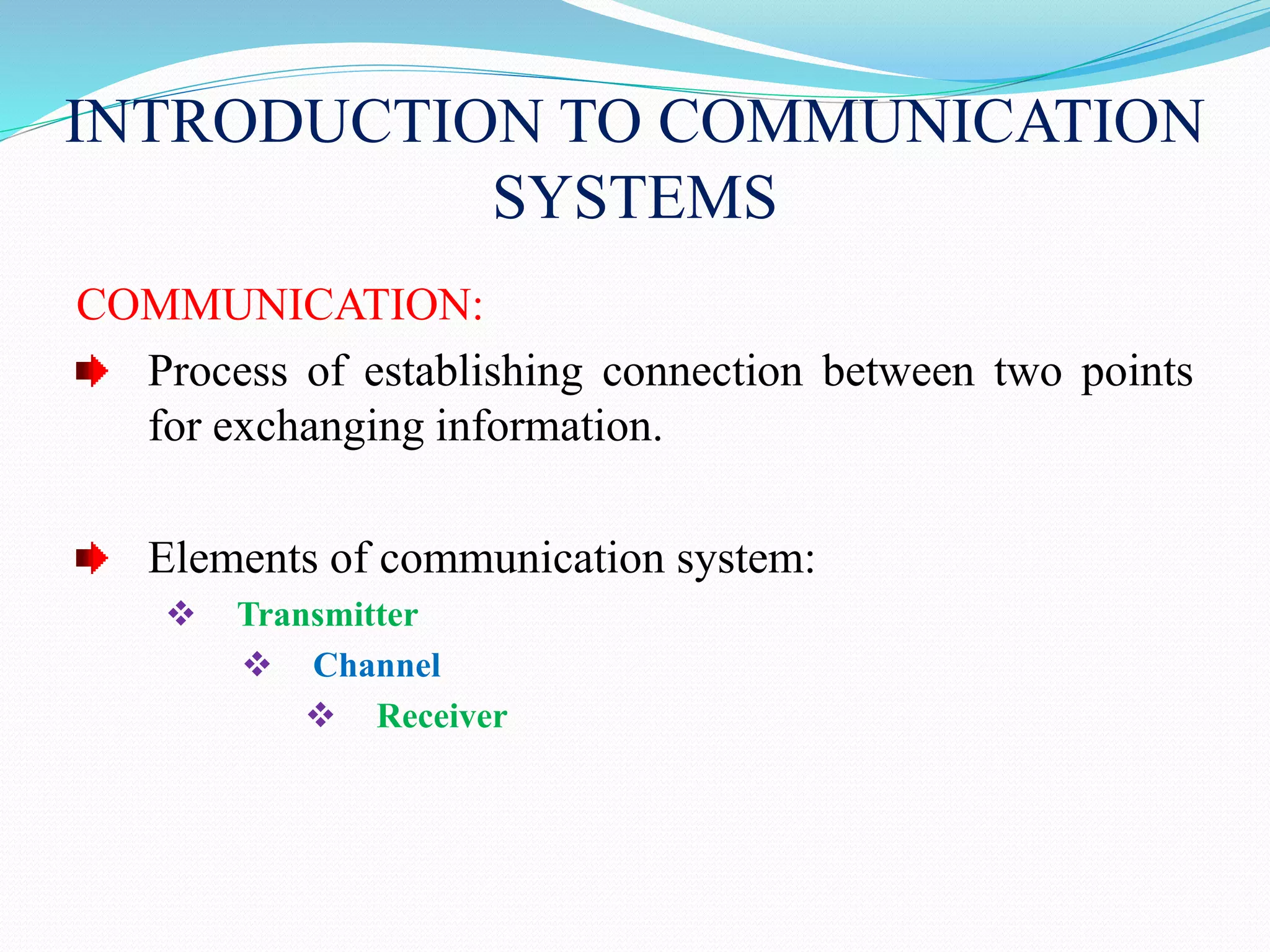
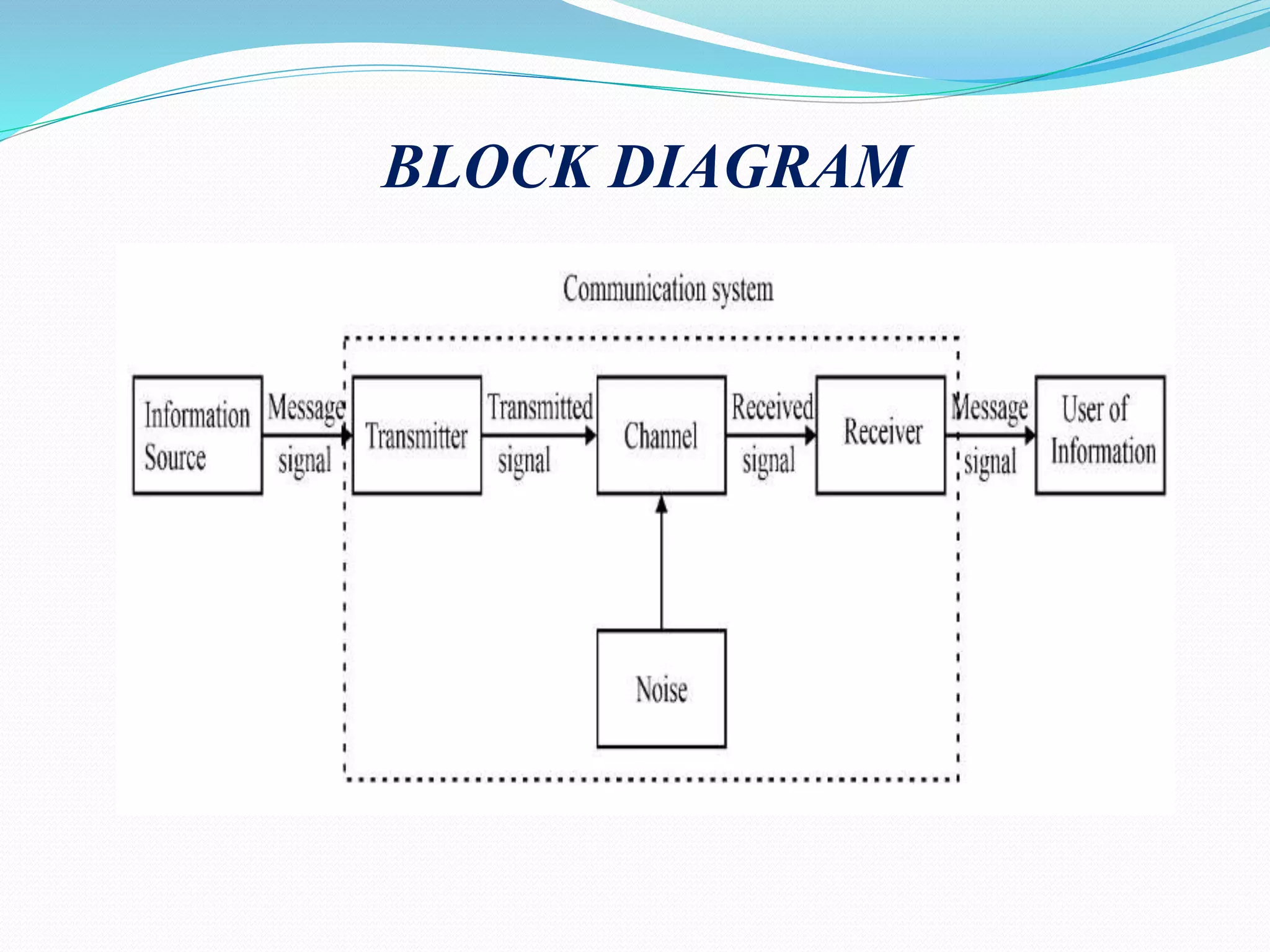
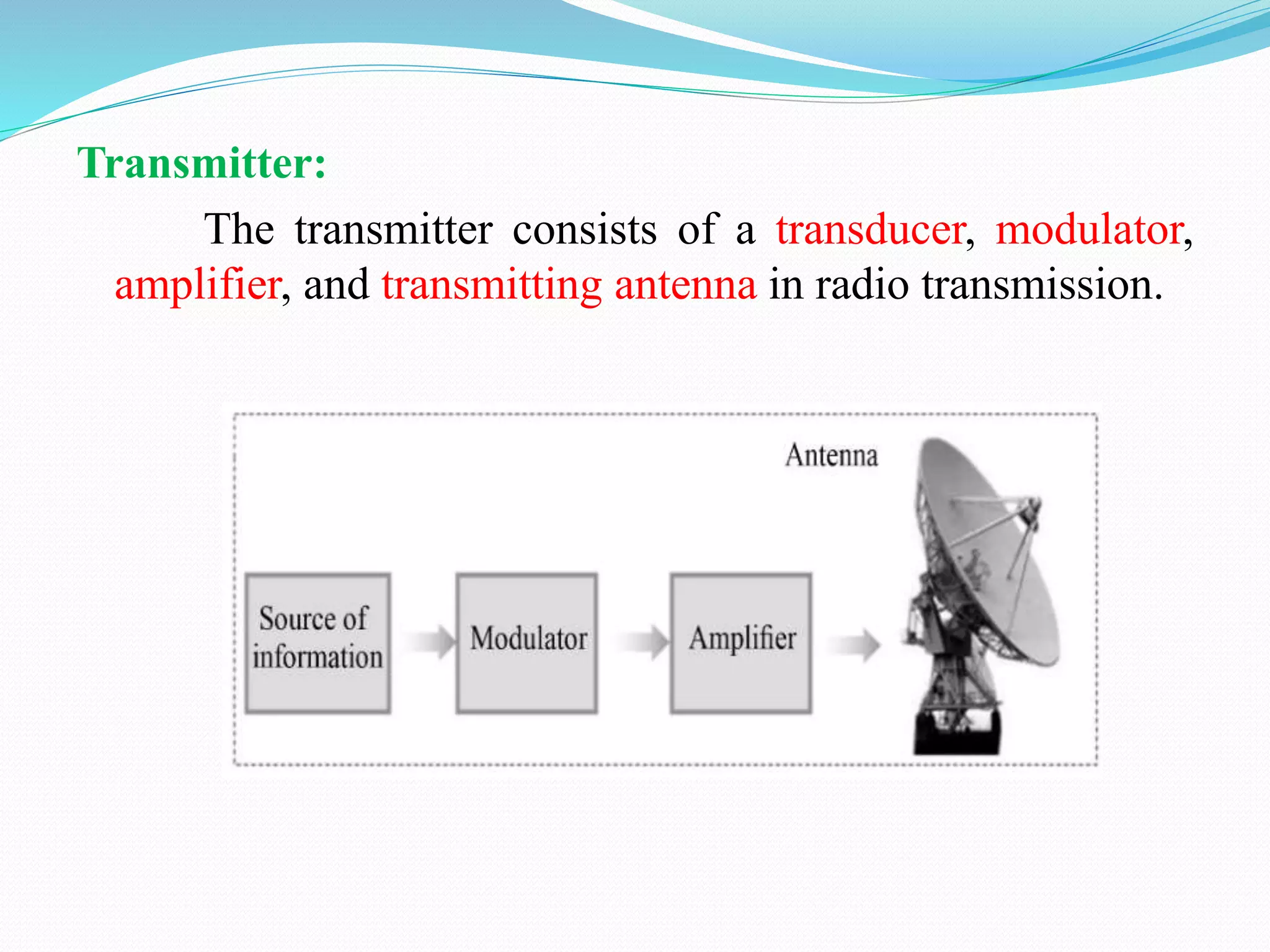
1) The document discusses analog communication systems including amplitude modulation. It defines key concepts like modulation, channels, transmitters and receivers.
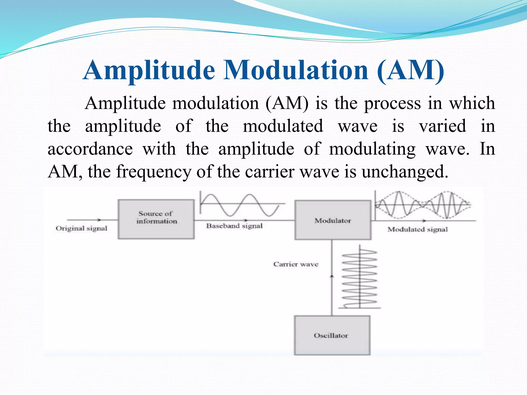
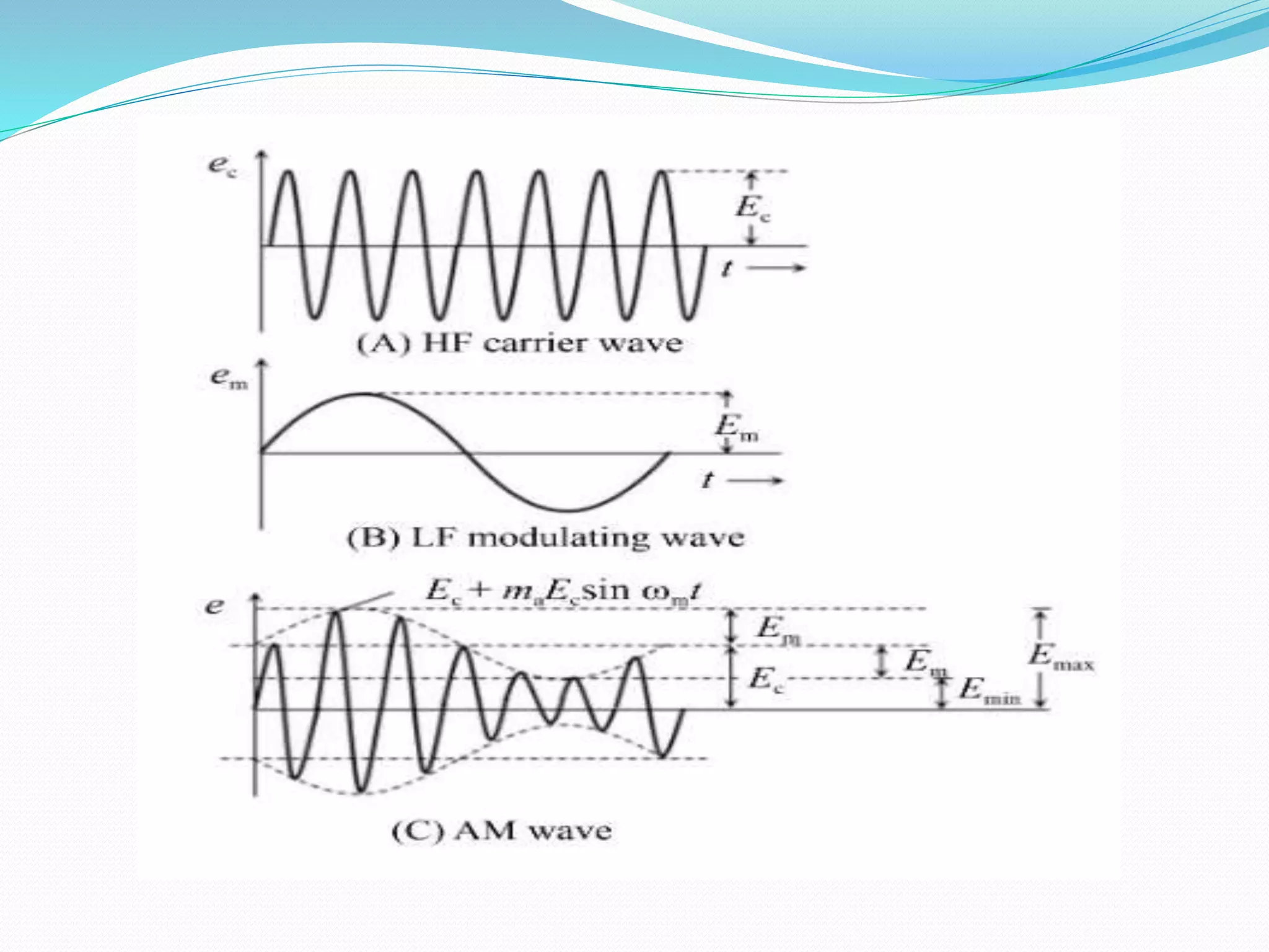
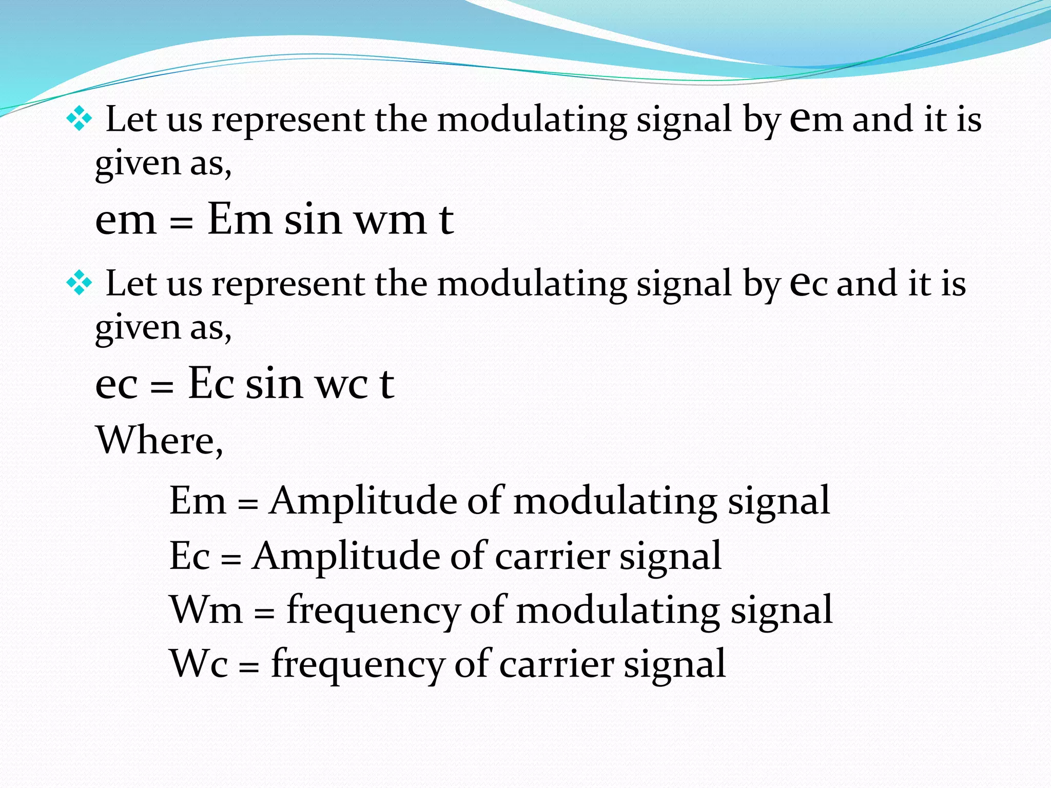
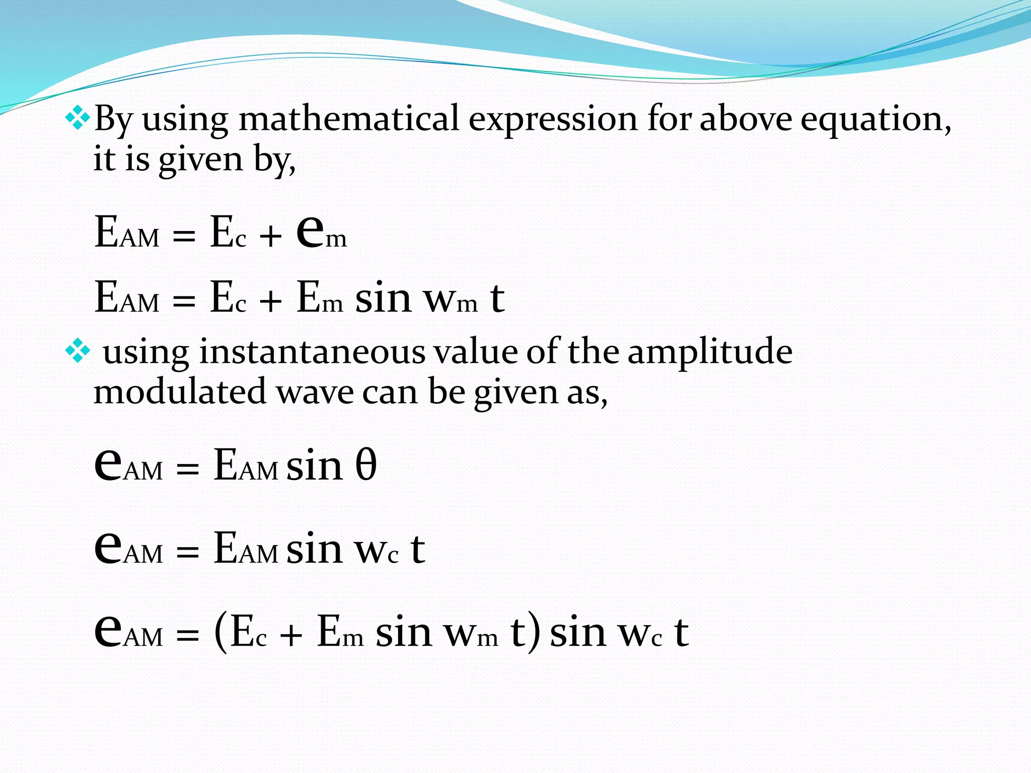
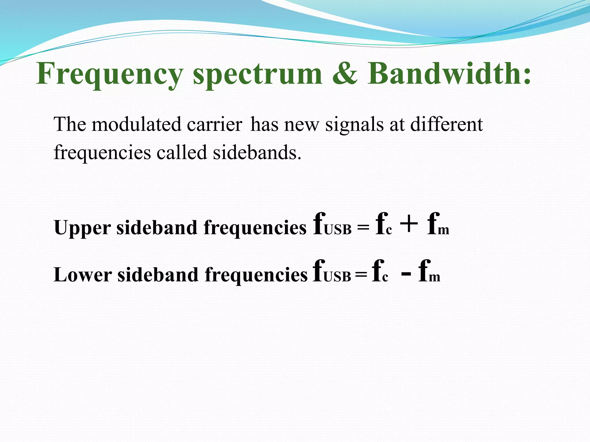
2) Amplitude modulation varies the amplitude of a carrier wave using a modulating signal. This generates sidebands at frequencies above and below the carrier frequency.
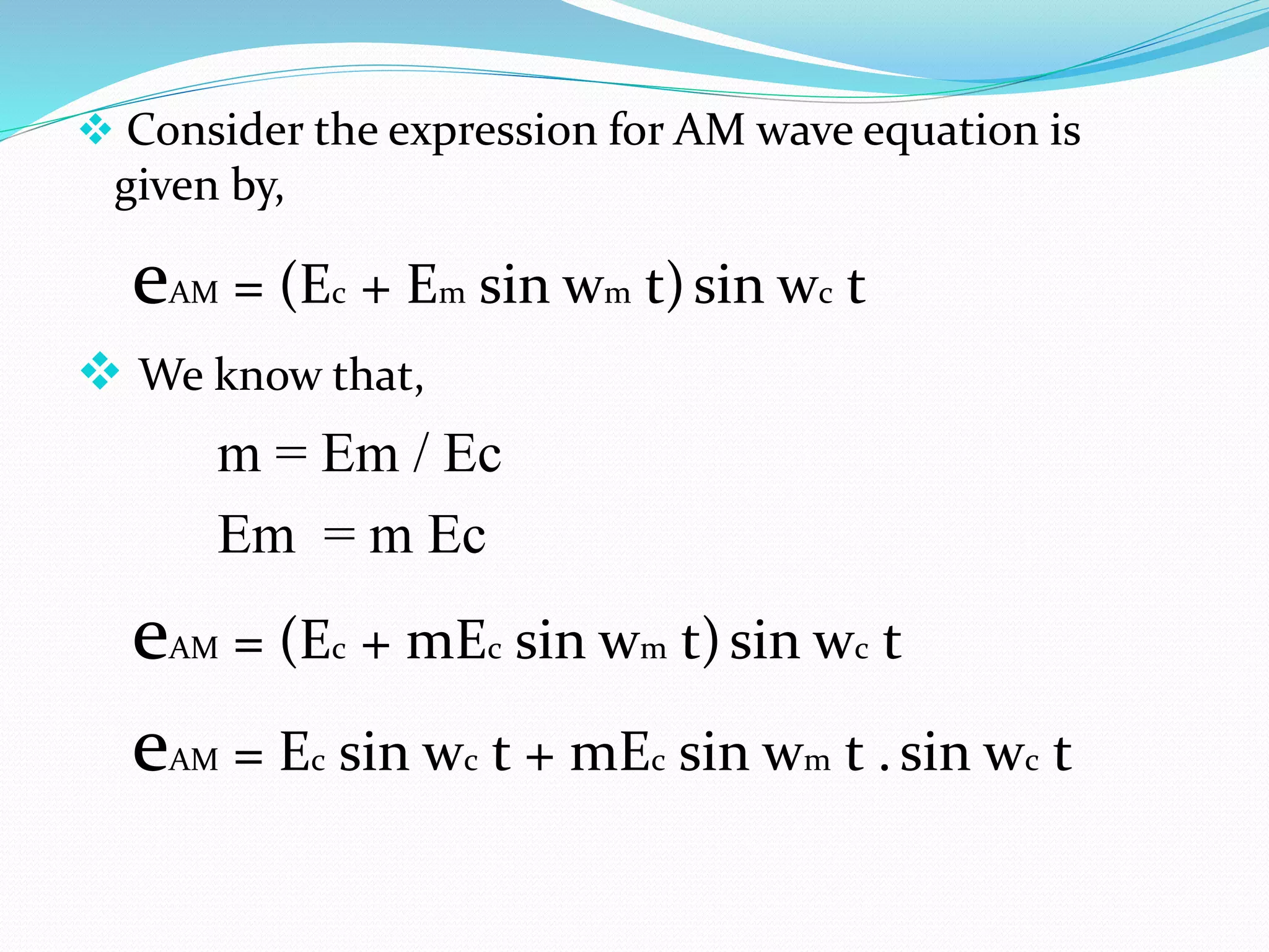
3) The modulation index is the ratio of the modulating signal amplitude to the carrier amplitude. It indicates the percentage of modulation.