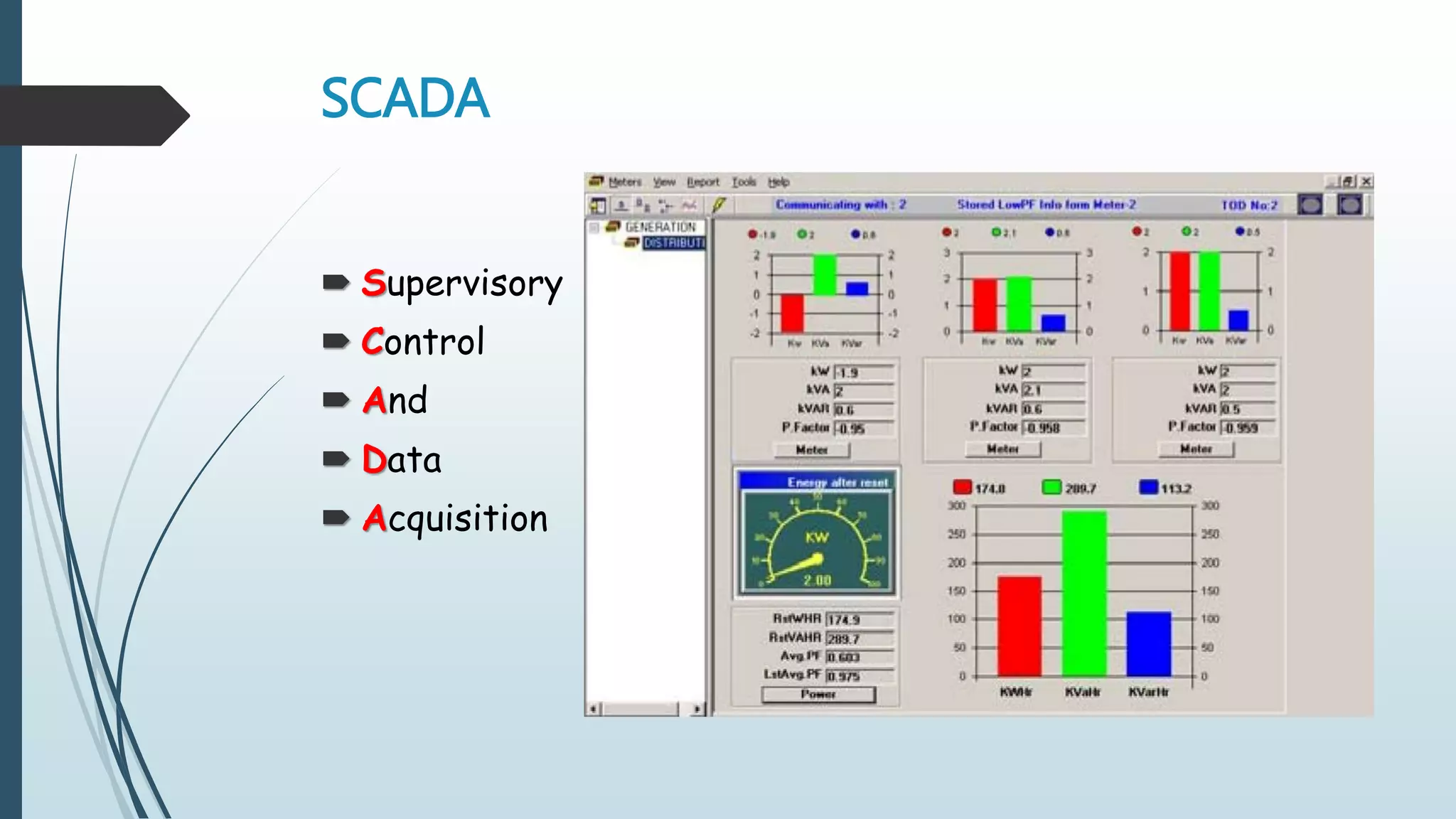
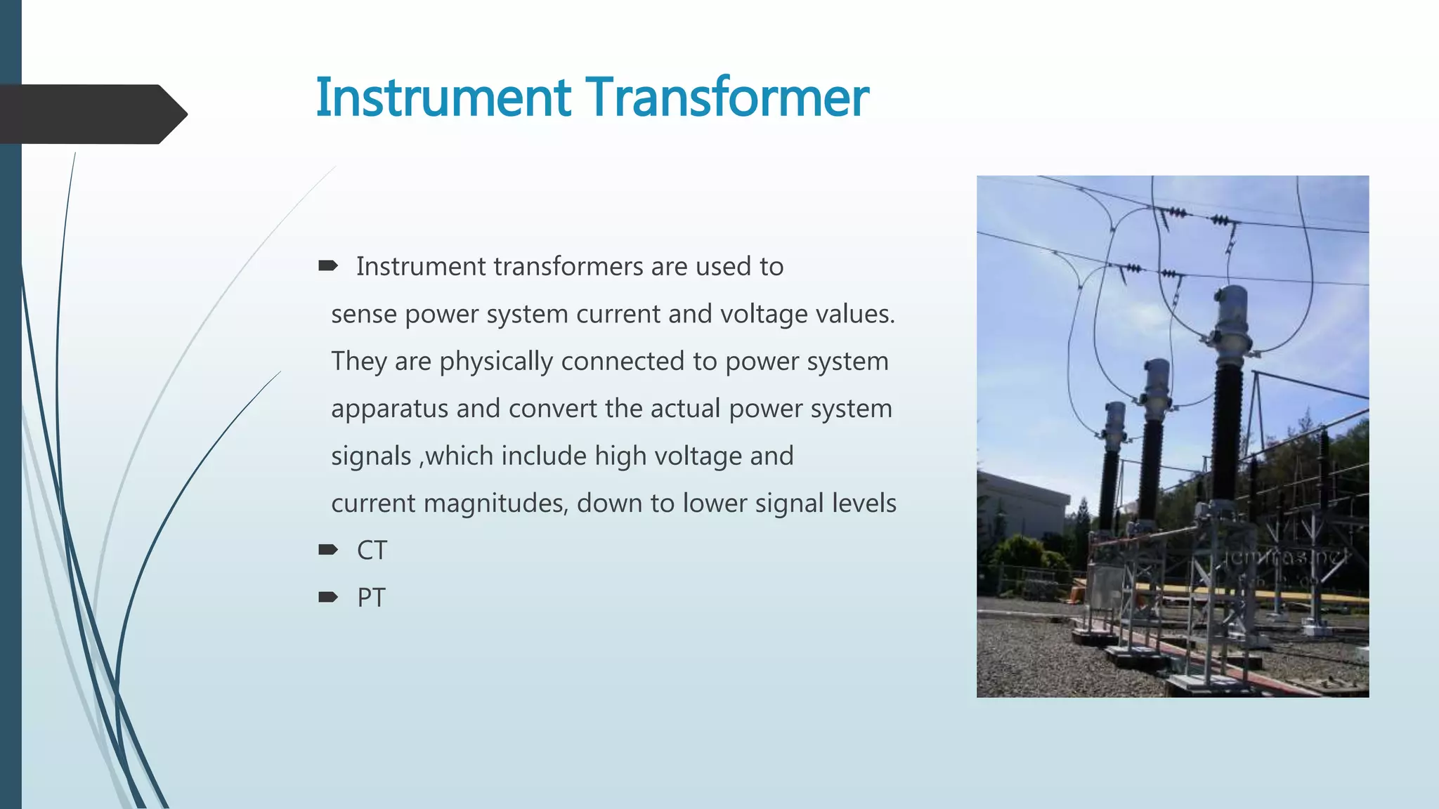
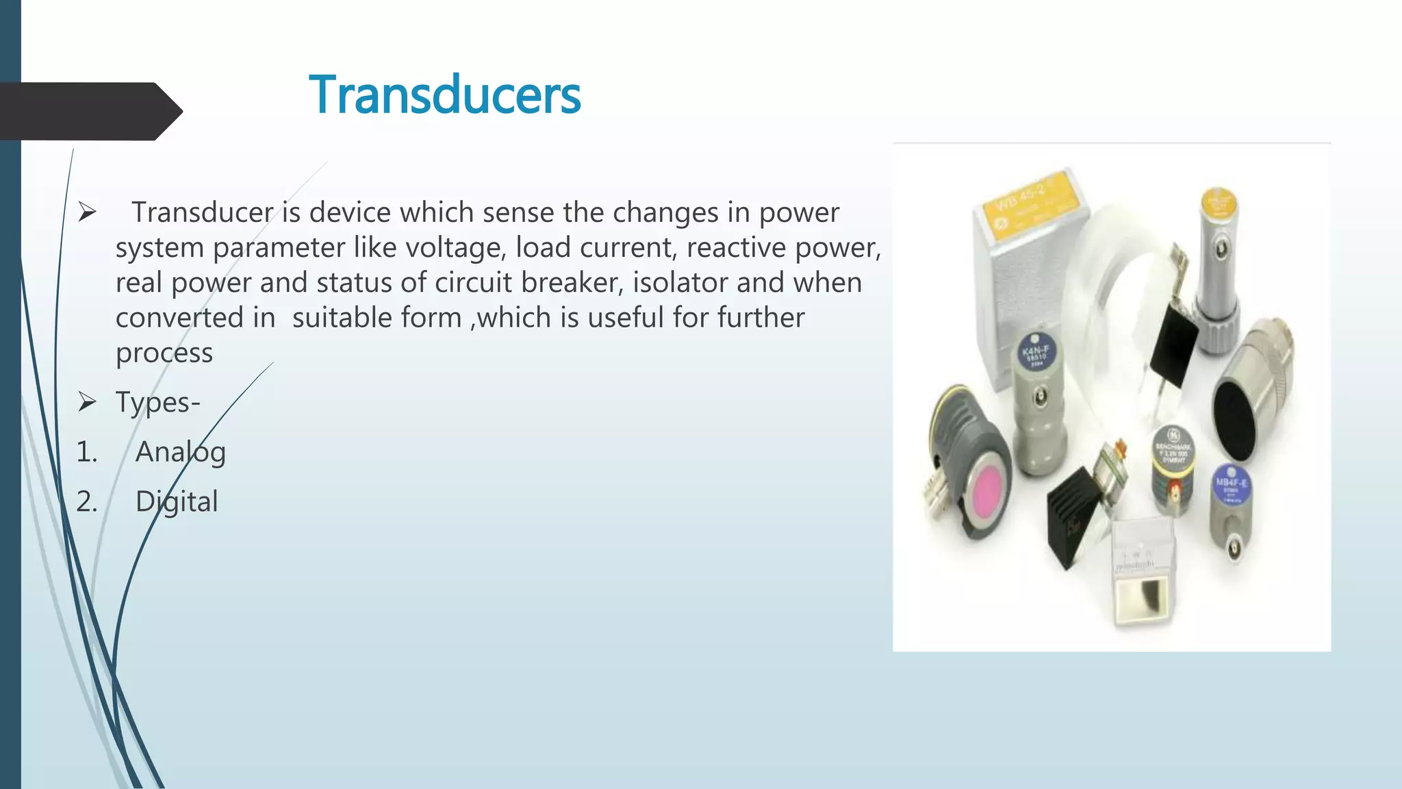
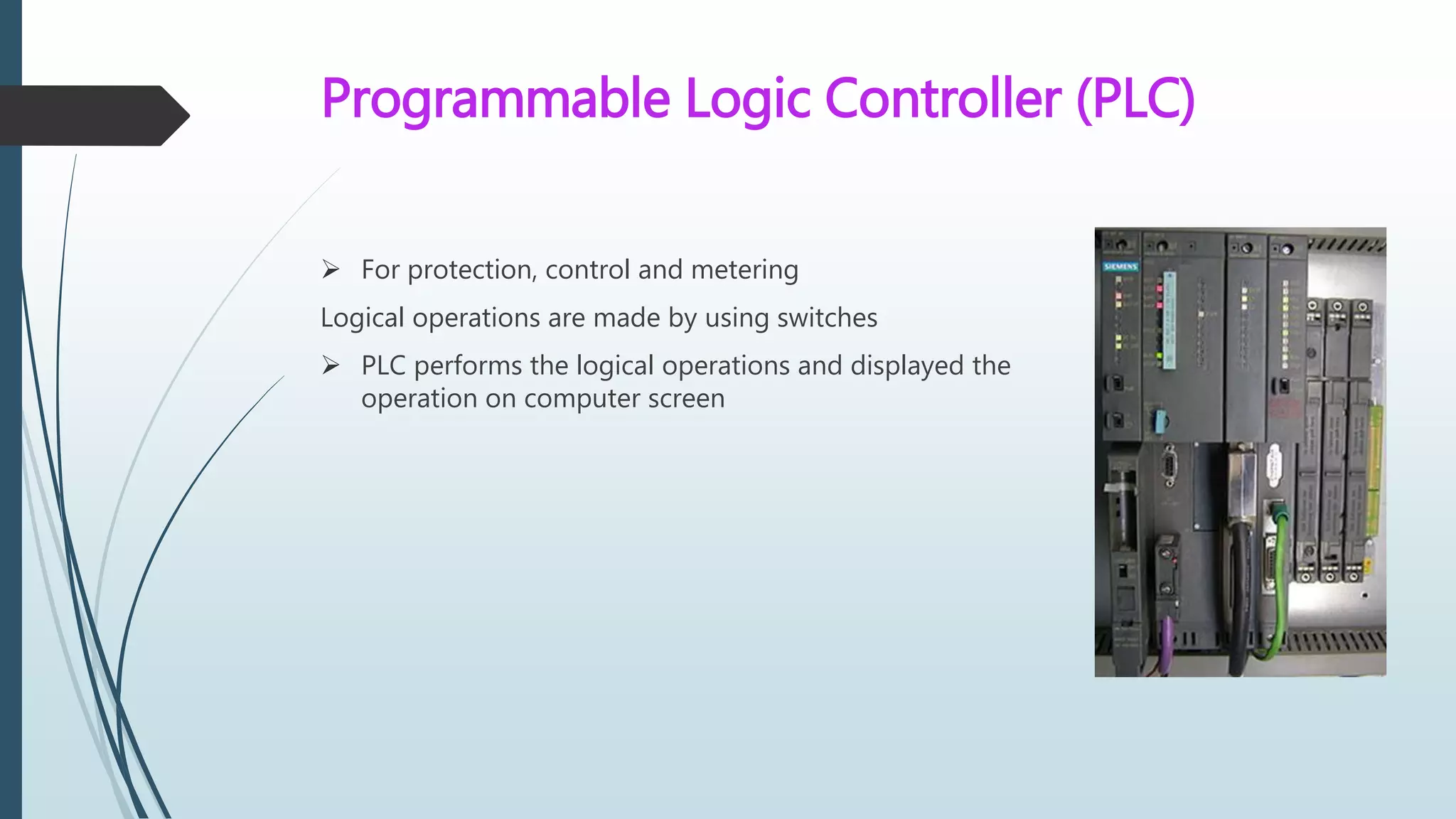
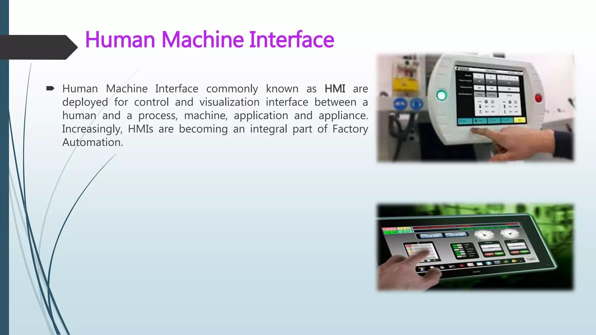
Power System Automation
Prepared by-
Dhiraj M. Bhalerao
B. E. Electrical
Roll no.- 02
Index
1. Introduction
2. SCADA
3. Components of SCADA
4. Process of SCADA in Power system
5. Advantages
6. Disadvantages
7. Applications
8. Conclusion
Introduction-
 Electrical power system-
Generation system – Generation of electricity by different sources
Transmission system -Generating station & Distribution substation are
connected by transmission system
Distribution – connects all transmission lines to load
What Is Power System Automation
 Electric protection
 Control
 Measurement
 Monitoring
SCADA
 Supervisory
 Control
 And
 Data
 Acquisition
Components Of SCADA
1. Instrument transformer
2. Transducer
3. Relay
4. RTU
5. Meter
6. Digital fault recorder
7. PLC
8. HMI
Instrument Transformer
 Instrument transformers are used to
sense power system current and voltage values.
They are physically connected to power system
apparatus and convert the actual power system
signals ,which include high voltage and
current magnitudes, down to lower signal levels
 CT
 PT
Transducers
 Transducer is device which sense the changes in power
system parameter like voltage, load current, reactive power,
real power and status of circuit breaker, isolator and when
converted in suitable form ,which is useful for further
process
 Types-
1. Analog
2. Digital
Relay
 A protective relay is an IED designed to sense power system disturbances and
automatically perform control actions on the I&C system and the power system to
protect personnel and equipment.
 Relays create metering information, collect system status information, and store
historical records of power system operation.
Remote Terminal Unit (RTU)
 RTU is a microprocessor-controlled electronic device that
interfaces transducer & MTU by transmitting telemetry data
to a master system, and by using messages from the master
supervisory system to control connected objects. Another
term that may be used for RTU is remote tele-control unit.
 Unit of RTU-
1) AE (analog input card),
2) DE (digital input card)
Meter
A meter is an IED that is used to create accurate
measurements of power system current, voltage, and
power values. Metering values such as demand and peak
are saved within the meter to create historical information
about the activity of the power system
Digital Fault Recorder
 A digital fault recorder (DFR), is an IED that
records information about power system
disturbances.
 It is capable of storing data in a digital
format when triggered by conditions
detected on the power system. Harmonics,
frequency, and voltage are examples of
data captured by DFRs.
Programmable Logic Controller (PLC)
 For protection, control and metering
Logical operations are made by using switches
 PLC performs the logical operations and displayed the
operation on computer screen
Human Machine Interface
 Human Machine Interface commonly known as HMI are
deployed for control and visualization interface between a
human and a process, machine, application and appliance.
Increasingly, HMIs are becoming an integral part of Factory
Automation.
Advantages
 Efficient with less manpower
 Flexible, Simple, Reliable
 Self Checking
 Portable
Disadvantages-
 Lack of train personal
 Initial cost is high
Applications -
 Smart Grid-
A smart grid is a modernized electrical grid that uses analogue or digital
information and communications technology to gather and act on information, such
as information about the behaviours of suppliers and consumers, in an automated
fashion to improve the efficiency, reliability, economics, and sustainability of the
production and distribution of electricity.
 Smart Meter –
A smart meter is usually an electronic device that records
consumption of electric energy in intervals of an hour or less and
communicates that information at least daily back to the utility for
monitoring and billing.
 Automatic Generation Control
In an electric power system, automatic generation control (AGC) is a system
for adjusting the power output of multiple generators at different power
plants, in response to changes in the load.
Conclusion-
 The government of India has decided to integrate all the state
power utilities. Unified load dispatch Centre has to be build.
So automation has lot more advantages as it increases
efficiency and increase standardization.
Any Questions
References
 1. J. B. Gupta, Electrical power system, SK publications, part II ,Jan 2013
 2. Gaur & Gaur, Automation in power distribution system: Present status,
 E-ISSN0976-7916, 2012
 3. Jason stamp & Michel Berg, Reference Model for Control and Automation Systems in
Electrical Power, vol., 10 oct. 2005
 4. National communication system, Supervisory Control And Data Acquisition (SCADA)
systems, Tech. info. Bulletin, Vol. NCS TIB 04-1, Oct 2004
 5. Power system automation, NPTEL, Dept. of elect engg., page no. 1-16, Sept. 2015
 6. Shabnam Rukhsar, SCADA in Transmission Line, IOSR Journal of Electrical and
Electronics Engineering, e-ISSN: 2278-1676, p-ISSN: 2320-3331,Page no. 67 to 71,2014
 7. http://www.iosrjournals.org
Dhiraj seminar # power system automation

Dhiraj seminar # power system automation

  • 1.
    Power System Automation Preparedby- Dhiraj M. Bhalerao B. E. Electrical Roll no.- 02
  • 2.
    Index 1. Introduction 2. SCADA 3.Components of SCADA 4. Process of SCADA in Power system 5. Advantages 6. Disadvantages 7. Applications 8. Conclusion
  • 3.
    Introduction-  Electrical powersystem- Generation system – Generation of electricity by different sources Transmission system -Generating station & Distribution substation are connected by transmission system Distribution – connects all transmission lines to load
  • 4.
    What Is PowerSystem Automation  Electric protection  Control  Measurement  Monitoring
  • 5.
    SCADA  Supervisory  Control And  Data  Acquisition
  • 6.
    Components Of SCADA 1.Instrument transformer 2. Transducer 3. Relay 4. RTU 5. Meter 6. Digital fault recorder 7. PLC 8. HMI
  • 7.
    Instrument Transformer  Instrumenttransformers are used to sense power system current and voltage values. They are physically connected to power system apparatus and convert the actual power system signals ,which include high voltage and current magnitudes, down to lower signal levels  CT  PT
  • 8.
    Transducers  Transducer isdevice which sense the changes in power system parameter like voltage, load current, reactive power, real power and status of circuit breaker, isolator and when converted in suitable form ,which is useful for further process  Types- 1. Analog 2. Digital
  • 9.
    Relay  A protectiverelay is an IED designed to sense power system disturbances and automatically perform control actions on the I&C system and the power system to protect personnel and equipment.  Relays create metering information, collect system status information, and store historical records of power system operation.
  • 10.
    Remote Terminal Unit(RTU)  RTU is a microprocessor-controlled electronic device that interfaces transducer & MTU by transmitting telemetry data to a master system, and by using messages from the master supervisory system to control connected objects. Another term that may be used for RTU is remote tele-control unit.  Unit of RTU- 1) AE (analog input card), 2) DE (digital input card)
  • 11.
    Meter A meter isan IED that is used to create accurate measurements of power system current, voltage, and power values. Metering values such as demand and peak are saved within the meter to create historical information about the activity of the power system
  • 12.
    Digital Fault Recorder A digital fault recorder (DFR), is an IED that records information about power system disturbances.  It is capable of storing data in a digital format when triggered by conditions detected on the power system. Harmonics, frequency, and voltage are examples of data captured by DFRs.
  • 13.
    Programmable Logic Controller(PLC)  For protection, control and metering Logical operations are made by using switches  PLC performs the logical operations and displayed the operation on computer screen
  • 14.
    Human Machine Interface Human Machine Interface commonly known as HMI are deployed for control and visualization interface between a human and a process, machine, application and appliance. Increasingly, HMIs are becoming an integral part of Factory Automation.
  • 15.
    Advantages  Efficient withless manpower  Flexible, Simple, Reliable  Self Checking  Portable
  • 16.
    Disadvantages-  Lack oftrain personal  Initial cost is high
  • 17.
    Applications -  SmartGrid- A smart grid is a modernized electrical grid that uses analogue or digital information and communications technology to gather and act on information, such as information about the behaviours of suppliers and consumers, in an automated fashion to improve the efficiency, reliability, economics, and sustainability of the production and distribution of electricity.
  • 18.
     Smart Meter– A smart meter is usually an electronic device that records consumption of electric energy in intervals of an hour or less and communicates that information at least daily back to the utility for monitoring and billing.
  • 19.
     Automatic GenerationControl In an electric power system, automatic generation control (AGC) is a system for adjusting the power output of multiple generators at different power plants, in response to changes in the load.
  • 20.
    Conclusion-  The governmentof India has decided to integrate all the state power utilities. Unified load dispatch Centre has to be build. So automation has lot more advantages as it increases efficiency and increase standardization.
  • 21.
  • 22.
    References  1. J.B. Gupta, Electrical power system, SK publications, part II ,Jan 2013  2. Gaur & Gaur, Automation in power distribution system: Present status,  E-ISSN0976-7916, 2012  3. Jason stamp & Michel Berg, Reference Model for Control and Automation Systems in Electrical Power, vol., 10 oct. 2005  4. National communication system, Supervisory Control And Data Acquisition (SCADA) systems, Tech. info. Bulletin, Vol. NCS TIB 04-1, Oct 2004  5. Power system automation, NPTEL, Dept. of elect engg., page no. 1-16, Sept. 2015  6. Shabnam Rukhsar, SCADA in Transmission Line, IOSR Journal of Electrical and Electronics Engineering, e-ISSN: 2278-1676, p-ISSN: 2320-3331,Page no. 67 to 71,2014  7. http://www.iosrjournals.org