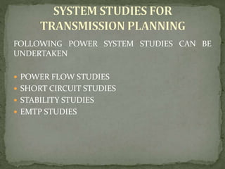
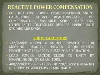
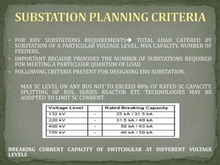
The document discusses guidelines for transmission system planning in India. It outlines that:
- The Central Electricity Authority is responsible for preparing transmission plans and coordinating planning agencies according to the Electricity Act 2003.
- The transmission system consists of the inter-state transmission system (ISTS) managed by the Central Transmission Utility and intra-state transmission systems (Inra-STS) managed by State Transmission Utilities.
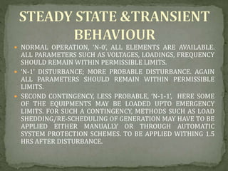
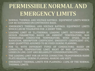
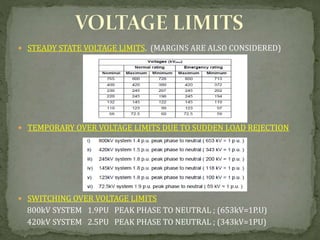
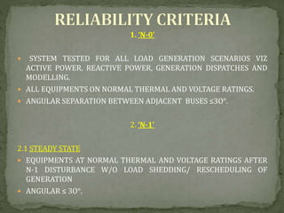
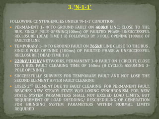
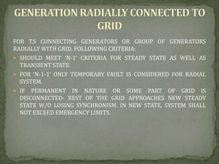
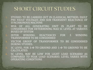
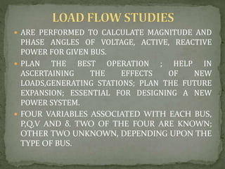
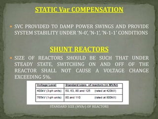
- Transmission planning involves power flow studies, short circuit studies, and stability studies to ensure system security, reliability and that all parameters remain within limits under normal ('N-0') and contingency ('N-1' and 'N-1-1') conditions.
This document discusses national and regional power system planning in India. It begins with an introduction to power system planning, including transmission versus distribution planning and long-term versus short-term planning. It then covers various aspects of planning such as generation planning, capacity resource planning, and transmission planning. The document outlines the five electricity regions in India and discusses the economic benefits of regional coordination in planning. It concludes with mentions of integrated resource planning and least cost utility planning strategies.
Load forecasting is essential for power system planning to estimate future demand and energy requirements. Accurate load forecasts are needed to determine generation capacity additions, transmission and distribution infrastructure requirements, fuel procurement, and other planning decisions. Load forecasts can predict short-term (1 hour to 1 week) loads with about 1-3% accuracy but long-term (over 1 year) forecasts are less accurate due to uncertainties in weather predictions. Load forecasting helps utilities make important decisions around power purchasing, generation, and infrastructure development.
Power system planning & operation [eceg 4410]Sifan Welisa
The document discusses power load forecasting and substation planning. It explains that accurate load forecasting is important for power system planning and operation. Several load forecasting methods are described, including those based on historical load data, economic factors, and standardized load curves. Load forecasts can be short, medium, or long-term. The document also discusses factors to consider in substation planning and design, such as location, equipment requirements, and configuration. Feasibility studies are important for assessing potential hydroelectric and substation projects.
Power system planning involves studies ranging from 1-10 years to determine generation, transmission, and distribution infrastructure needs. Key aspects of transmission planning include load forecasting, generation expansion planning to meet load, substation expansion planning, network expansion planning to transmit power from generators to loads, and reactive power planning. Both static planning looking at single time periods and dynamic planning considering multiple time periods simultaneously are used. Transmission planning is interconnected with generation planning, as transmission systems deliver power from generators to loads.
Economic load dispatch(with and without losses)Asha Anu Kurian
The document discusses unit commitment in power systems. Unit commitment involves determining the optimal schedule for starting up and shutting down generators to meet changing load at minimum cost while satisfying operational constraints. These constraints include minimum up and down times for generators, crew constraints, transition costs, and constraints related to different generator types like hydro, nuclear, and generators requiring minimum output. The objective is to determine the combination and scheduling of generators that supplies the load as economically as possible over a given period.
This document discusses constraints and load flow analysis in power systems. It outlines four key constraints: active power constraint, reactive power constraint, voltage magnitude constraint, and load angle constraint. It also describes load flow analysis as a balanced mechanism between demand and generation under incremental loading. Load flow analysis is important for the safe and future operation of power systems. The document further discusses bus classification, basic power flow conditions including the proportional relationships between reactive power and voltage and active power and load angle. It also covers the development of the Y-bus matrix considering line resistances and inductances alone and then including line capacitances.
The document discusses load forecasting techniques and scheduling procedures in India's power system. It provides an overview of load forecasting, including the factors that affect load and different forecasting methods like extrapolation and correlation. It also describes the responsibilities of different load dispatch centers in India for scheduling generation and load. The scheduling procedure involves various timelines for generators to declare availability, beneficiaries to submit requisitions, and final schedules to be issued.
In microgrid, if fault occurs or any other contingency happens, then the problems would be created which are related to power flow, also there are various protection schemes are used for minimize or eliminate these problems.
Voltage control is used for reactive power balance and P-f control is used for active power control.
Various protection schemes such as, over current protection, differential protection scheme, zoning of network in adaptive protection scheme are used in microgrid system .
This document discusses fault level calculations in electric power systems. It explains that fault level calculations are necessary to select protective devices, circuit breakers, and equipment that can withstand short circuit currents. The document outlines the procedure for calculating fault levels, which involves representing the system with a single line diagram, choosing a base MVA, calculating per unit reactances, determining the equivalent reactance to the fault point, and using formulas to calculate fault MVA and current. It also discusses how current limiting reactors can be used to insert additional reactance and reduce short circuit currents to match circuit breaker ratings.
FACTS DEVICES AND POWER SYSTEM STABILITY pptMamta Bagoria
This presentation provides an overview of Flexible AC Transmission Systems (FACTS) and power system stability. It defines FACTS as using power electronics to control power flow and enhance transmission system capacity and stability. The document outlines different types of FACTS controllers including series compensation and shunt compensation. It also classifies power system stability into rotor angle stability, voltage stability, and frequency stability and discusses factors that can lead to losses of each type of stability.
The document discusses load forecasting for power system planning. It defines load forecasting as projecting future load requirements using a systematic process. Accurate load forecasting is important for determining generation, transmission, and distribution capacity needs. The document describes different types of loads including domestic, commercial, industrial, agricultural, and others. It discusses various load forecasting techniques including extrapolation, correlation, and combinations. Key factors like weather impacts are also summarized.
What is islanding ?
Consider the power network as shown in fig.1
Now if we disconnect the line AB from the infinite transmission grid there will be an isolated region . The D1, D2 are power sources (eg : inverter , solar power cells ). The power generated in this region is fed to the island only.
We see that there no longer is any control over the island voltage at the bus X . Also there is no mechanism here for control of frequency.
This state is referred to as islanding.
Generation shift factor and line outage factorViren Pandya
This is animated presentation to let students have an idea about use of generation shift factor and line outage distribution factor to assess power system security by contingency analysis. Entire presentation is prepared from a very nice book authored by Wood.
This document discusses distributed generation, which refers to small-scale power generation located near the end users. It can include sources like solar panels, wind turbines, fuel cells, and cogeneration. Distributed generation has advantages like reduced transmission losses and improved supply security. However, it also presents challenges like impacts on power quality from issues such as voltage regulation, grounding, harmonics, and islanding effects. The document outlines different distributed generation technologies and concludes that its integration into the power system is possible if interconnection designs adequately address power quality and safety considerations.
This document provides an overview of the EE2402 Protection & Switchgear course presented by C.Gokul. It includes the course syllabus, units covered, textbook references and introductory content on power system basics, components, faults, protection elements, relay terminology and essential qualities of protection systems. The key topics discussed are types of faults in power systems, importance of protective schemes, elements of a protection system including current transformers, voltage transformers, relays and circuit breakers. Neutral earthing methods with a focus on Peterson coil are also introduced.
The document provides details of the planning and design of the distribution system for Malda Polytechnic. It includes:
- An introduction to the project members and the importance of planning distribution systems.
- Details of the load survey conducted, including load calculations for hostels, offices, and buildings on campus.
- Definitions of key terms like connected load and demand factors.
- Calculations of the total load for the campus and determination of the optimal load center location.
- Considerations for future load prediction and design of the transmission and distribution system in accordance with Indian electricity rules.
This presentation provides an overview of power quality, including definitions of power quality, common power quality disturbances like sags, swells, harmonics and interruptions. It discusses the increased sensitivity of modern electronic equipment to power quality issues. Real-time power quality monitoring systems are described that can identify issues, locate their sources, and help utilities and customers mitigate problems to reduce costs and equipment damage. The benefits of power quality monitoring include improved reliability, preventative maintenance, and identification of sensitive equipment needing protection.
Introduction
Power Quality Problems
Power Quality Measurement Devices
Power Quality Terminology
Power Quality Standards
Unbundled Power Quality Services
Power Quality Monitoring
Benefits of Power Quality
Conclusion
References
This document discusses transformer protection philosophy and methods. It describes various types of faults that can occur in transformers like ground faults, phase-to-phase faults, interturn faults, and core faults. It also discusses mechanical protections like Buchholz relay, sudden pressure relay, pressure relief valve, and temperature indicators. Electrical protections discussed include biased differential relay protection and harmonic restraint. The document provides details on how these protections work and their settings.
This document discusses power system stability and microgrids. It defines power system stability and classifies it into several types including rotor angle stability, voltage stability, and frequency stability. It also discusses microgrids, their interconnection to main grids for availability and economic benefits, and methods for connecting microgrids using switchgear or static switches. In conclusion, it states that power system stability is important for normal operation and can be improved through devices like capacitors and FACTS controllers, and that microgrids satisfy local loads while reducing transmission losses through local renewable generation.
A brief and basic presentation of interconnections of pwer system,it covers all the basic aspects of power system interconnection that how systems can be built with interconnections
The document discusses various power system stability issues and remedial actions. It covers four aspects of power system stability: frequency stability, angular stability, voltage stability, and issues related to renewable integration. For each stability aspect, it provides examples of potential instability events, such as pole slip due to delayed fault clearance. It also outlines remedial actions that can be taken, such as improving reactive support and protection coordination, to prevent or mitigate instability events. Overall, the document aims to educate about power system stability challenges and effective measures to maintain reliable grid operations.
These slides presents the different challenges and issues related to DG integration to Micro-grid distribution systems. The possible solutions are also presented. Later of the class I will try to upload the mathematical presentations and simulation results related to each protection scheme. However, your suggestions are always welcome.
The document provides an overview of substation protection basics. It discusses why protection is needed to detect faults and isolate faulty equipment. The main types of faults are described along with the causes of insulation failures. The types of protection principles covered include overcurrent, differential, pilot wire, and distance protection. Key elements of a protection scheme like circuit breakers, relays, batteries, and transformers are also mentioned.
The document discusses electric power supply systems and transmission. It describes how electric power is generated at power stations, transmitted over long distances via transmission lines, and then distributed to consumers. There are three main components of an electric supply system: the power station, transmission lines, and the distribution network. Transmission is typically done using high voltages for efficiency and reduced line losses. While DC transmission has advantages, AC transmission is now universally used due to the ability to easily transform voltages using cost-effective transformers.
FERC Order 1000: Understanding Transmission Planning in a New ParadigmDNVGLEnergy
FERC Order 1000 requires transmission providers to consider public policy and interregional coordination in transmission planning. It also requires removing rights of first refusal and implementing regional and interregional cost allocation methods. The presentation discusses how these principles have been implemented by transmission providers like SPP, MISO, CAISO and PJM through competitive bidding processes and direct sponsorship models for transmission project selection. It also outlines the qualification process for developers to participate and submit detailed project proposals for consideration in regional transmission plans.
2014 Transmission Annual Planning Report - Non-network solutionsTransGrid AU
The 2014 NSW Transmission Annual Planning Report Forum was held on August 5th in Sydney with over 100 stakeholders. Representatives from TransGrid and AEMO discussed TransGrid's future plans, including investing $18 million from 2014 to 2019 in a Demand Management Innovation Allowance to facilitate non-network solutions and defer potential transmission investment costs of around $400 million for the Powering Sydney's Future project through demand response programs. TransGrid also intends to issue a request for proposals for demand response for Powering Sydney's Future as early as summer 2014/15.
Best Practices for NEPA Compliance and Related Permitting for Projects on In...Trihydro Corporation
Regulatory framework for permitting wells and pipelines
Typical timeframes and hang-ups in the permitting process
Best practices for permitting
Programmatic approaches to well field development on tribal lands, including potential benefits to tribes, Bureau of Indian Affairs (BIA), and operators
Bob Smith Platts June 18 2014 Transmission Planning DevelopmentRobert Smith
Bob Smith discussed resource adequacy and transmission planning at APS. He outlined that (1) APS must plan for peak demand increases while integrating more renewable energy and customer resources, (2) their generation fleet and transmission system need to evolve to accommodate changing supply and demand patterns from more intermittent resources and customer solar, and (3) modernizing generators like new combustion turbines at Ocotillo and investing in grid technologies will provide flexibility to integrate renewables and maintain reliability.
5 cired2013 planning of power distribution systemsDutch Power
This document discusses papers being presented at the CIRED 2013 conference. It provides an overview of the conference, including the number and origins of papers, as well as the topics being covered. It then reviews several individual papers presented, summarizing their objectives, innovations, and conclusions. The papers discussed focus on topics like risk assessment, network development, and distribution planning.
The document explains the 5 most important synthesis modules: oscillator, filter, amplifier, envelope, and LFO. It describes how the oscillator generates the basic audio signal through different waveforms. The filter is used to alter this signal by removing certain frequencies. The amplifier controls volume over time using an envelope generator that determines the attack, decay, sustain, and release of a sound. The LFO produces low frequency signals that can be used to modulate other modules for effects like vibrato. Understanding these core synthesis modules is crucial for working with subtractive synthesis in a digital audio workstation.
The document discusses estimation and different types of estimates used to estimate population parameters based on sample data. Point estimates provide a single value while interval estimates provide a range of values. Good estimators are unbiased, efficient, and consistent. Common point estimators are the sample mean and sample standard deviation. Interval estimates use the point estimate plus/minus a margin of error calculated from the standard error. Confidence intervals provide a probability that the population parameter lies within the interval estimate.
Flora Flygt: Clean Power Plan Impact on Transmisssion Planning, Development a...EnergyTech2015
EnergyTech2015.com
Track 1 Session 2
THE U.S. ENVIRONMENTAL PROTECTION AGENCY CLEAN POWER PLAN: HOW WILL IT AFFECT THE ELECTRIC UTILITY INDUSTRY NOW AND IN THE FUTURE?
On June 2, 2014, the U.S. EPA, proposed a plan with the stated purpose of reducing carbon emissions from electric generating units, under Section 111(d) of the Clean Air Act. The CPP sets a CO2 emission target for each state, and utilizes four “building blocks” in devising those rates. The CPP suggests power to be dispatched based upon environmental considerations. Today, regional electric markets dispatch power based upon economic considerations and not environmental considerations. More than four million entities submitted comments on the proposed CPP and on August 3, 2015, the U.S. EPA issued their final plan. What is the overall affect on states, utilities, and ratepayers? What is the timeline for implementation of the CPP? What does the plan mean for the future electric generation mix? How will reliability and prices be impacted? What kinds of technology and regulatory policy changes will be needed?
Moderator: Maria Ilic, CMU Professor
Asim Haque, PUCO Commissioner
Flora Flygt, Strategy Planning & Policy Advisor, American Transmission Company
India's power sector faces significant challenges with transmission and distribution (T&D) losses, which occur at both the utility and consumer levels. T&D losses in India are around 33%, much higher than in other countries. The government has implemented several programs and regulatory reforms to strengthen infrastructure and reduce losses through modernizing systems, encouraging private participation, and setting independent regulatory bodies to oversee the sector.
Bitcoin, Blockchain and the Crypto Contracts - Part 2Prithwis Mukerjee
Where we explain how the cryptographic ideas are used to create a crypto asset on the block chain. This one part of a three part slide deck. For the full deck and the context please visit http://bit.ly/pm-bbc
Deicing of transmisson line by dielectrc lossesbindasbhabani
This document summarizes a seminar presentation on de-icing of transmission lines using dielectric losses. The presentation discusses how ice formation can cause failures and outages, and introduces de-icing through applying a high frequency excitation to cause dielectric heating within the ice. It describes dielectric and skin effect heating mechanisms, and proposes combining the effects with a 100kHz field to achieve uniform ice melting. The presentation covers dielectric loss principles, de-icing types, advantages of reducing costs and applicability to live lines, and disadvantages of potential interference. It concludes dielectric heating is a promising approach for de-icing transmission lines.
Introduction to Power Quality: Terms and definitions of transients,
Long Duration Voltage Variations: under Voltage, Under Voltage and Sustained Interruptions
; Short Duration Voltage Variations: interruption, Sag, Swell; Voltage Imbalance; Notching D C offset,; waveform distortion; voltage fluctuation; power frequency variations
Transmission and distribution line design finalBhanu Poudyal
Transmission Line designed on basis of data available for a given Hydropower system.
Looking this document you can yourself design the Transmission Line system.
DESIGN ,ANALYSIS &COMPARISON OF VARIOUS CONTROLLERS FOR DC MOTOR SPEED CON...Varun Kambrath
This document discusses the design, analysis, and comparison of various controllers for DC motor speed control. It first introduces DC motors and their applications. It then presents the modelling and characteristics of a sample DC motor. The document analyzes and compares the performance of open loop, closed loop, proportional, integral, proportional-integral, proportional-derivative, and proportional-integral-derivative controllers for the motor. It evaluates the controllers based on rise time, settling time, overshoot, and steady state error. Finally, it examines the gain and phase margins of the controlled motor system.
Optimizing utilization and operating efficiency in electricity delivery system is one of smart grid’s characteristics. Transmission and distribution infrastructure includes transmission lines, substations, and distribution feeders. One estimate has put the potential in reducing distribution losses through smart grid deployment at 30%. In this report Zpryme looks at the distribution system portion of the smart grid and the portfolio of technologies that are being deployed to optimize the distribution infrastructure.
Download
Electricity in India: Developments, Issues, & RemediesShardul Kulkarni
Date: 11th November 2011
Electricity in India: Developments, Issues, and Remedies
The term ‘Electricity’, right from its inception in the English language in 1600, has gone way ahead to become one of the indispensable needs of humans. There is no need to try for finding out the uses of electricity. On similar grounds, in India its very first public use begun in 1899 and now it has become backbone of the economy. But this emerging basic necessity of man is still scarce in our country.
India, being the world’s fifth largest power generating country, remains below the world average of per capita consumption. It is also facing an acute power shortage and many other adversities. To tackle these odds the government agencies are giving all their efforts. This presentation is based on a brief study of power scenario in India and deals with some of the major Developments, Issues, and Remedies.
The description involves snippets on development of various organizations with specific goals for improving the status of power sector; serious issues to be tackled facing our nation; remedial plans of these bodies and the role which we could play in supporting them.
statcom-grid connected wind energy generating system for power qualityy impro...Venu Gopal
—Injection of the wind power into an electric grid affects the power quality. The performance of the wind turbine and thereby power quality are determined on the basis of measurements and the norms followed according to the guideline specified in International Electro-technical Commission standard, IEC-61400. The influence of the wind turbine in the grid system concerning the power quality measurements are-the active power, reactive power, variation of voltage, flicker, harmonics, and electrical behavior of switching operation and these are measured according to national/international guidelines. The paper study demonstrates the power quality problem due to installation of wind turbinewith the grid. In thisproposed scheme STATic COMpensator (STATCOM) is connected at a point of common coupling with a battery energy storage system (BESS) to mitigate the power quality issues. The battery energy storage is integrated to sustain the real power source under fluctuating wind power. The STATCOM control scheme for the grid connected wind energy generation system for power quality improvement is simulated using MATLAB/SIMULINK in power system block set. The effectiveness of the proposed scheme relives the main supply source from the reactivepower demand of the load and the induction generator. The development of the grid co-ordination rule and the scheme for improvement in power quality norms as per IEC-standard on the grid has been presented
Study of Vector Control Algorithm and Inverter design for BLDC Motor, V/f con...Amol Mahurkar
This document summarizes a study on vector control algorithms and inverter design for BLDC motors. It discusses the objectives of studying BLDC motor operation, different control algorithms including vector control, and inverter design. It also covers V/F control of induction motors. Key topics covered include Clarke/Park transformations, sensorless control, inverter topologies, and a comparison of vector and V/F control techniques. The document is authored by engineering students and provides an overview of various motor control concepts and algorithms.
This document discusses defense mechanisms in the Indian power grid. It begins by outlining the operational states of the grid as normal, alert, emergency, and restorative. It then discusses key aspects of power system reliability including adequacy and security.
The document outlines several defense mechanisms used in the Indian power grid including system protection schemes, automated under-frequency load shedding (AUFLS) triggered by low frequency thresholds, under-voltage load shedding triggered by low voltages, transmission line load trimming schemes, and islanding schemes. Specific examples of system protection schemes are provided for different generation plants and transmission corridors.
Phase-ground short-circuit current of the transformer and the generator is calculated to determine the limit current of the neutral grounding resistor. The resistor is designed to limit the failure current to 10% of this short-circuit current. This value shall be optimal to allow detection of the selected limited fault current value by the relays. Therefore, primary value of the current transformers used on the neutral grounding resistor can be different from the limited fault current value.
More information:https://aktif.net/en/product-and-services/Grounding-Resistors/neutral-grounding-resistors
This slide presents about the basic and importance about load shedding in smart microgrid distribution systems. Later of the class i will discuss about in detail on the process of executing the load shedding.
This document provides an overview of switchgears and protective devices used in power systems. It discusses substations, faults and abnormal conditions, fault calculations, the fault clearing process, protective relaying, and power system stability. Protective devices like circuit breakers, fuses, and relays are installed at different voltage levels and switching points to ensure reliable power supply and isolate faults. Substations are used to change voltage levels and switch equipment in and out of the system. Faults can occur due to insulation failures, breaks, or mechanical issues and their severity is estimated through fault current calculations. Relays detect faults and signal circuit breakers to clear the fault and restore the system. Stability is maintained by keeping the rotor and st
1) The document describes the performance of a quadrilateral relay for protection of extra high voltage transmission lines during faults with high resistance.
2) A PSCAD/EMTDC model of a 300km transmission line is developed and a quadrilateral relay scheme with two zones is designed and tested under different fault conditions.
3) Simulation results show that the quadrilateral relay can accurately detect faults located in zones 1 and 2 and is well-suited for providing flexible protection during high resistance faults on EHV transmission lines.
Power Swing Phenomena and Comparative Study of Its Detection on Transmission ...ijsrd.com
Power systems are subject to a wide range of small or large disturbances during operating conditions. Small changes in loading conditions occur continually. The power system must adjust to these changing conditions and continue to operate satisfactorily and within the desired limits of voltage and frequency. The power system should be designed to survive larger types of disturbances, such as faults, loss of a large generator, or line switching. Certain system disturbances may cause loss of synchronism between a generator and rest of the utility system, or between interconnected power systems of neighboring utilities. If such a loss of synchronism occurs, it is imperative that the generator or system areas operating asynchronously are separated immediately to avoid widespread outages and equipment damage. Here it is described to distinguish between power swing and real fault. It is also discussed recent enhancements in the design of out of step tripping and blocking protection functions that improve the security and reliability of the power system. In addition to that the behavior of distance relay element during power swing and during fault is simulated using MATLAB and SIMULINK simulations.
Performance, Modelling & Simulation of Frequency Relays for Distributed Gener...Niraj Solanki
The document discusses modeling and simulation of an adaptive frequency relay for distributed generation protection. It presents:
1) Performance curves showing the islanding detection capability of frequency relays depends on active power imbalance.
2) A model for an adaptive frequency relay that can automatically change settings based on whether the microgrid is connected to or isolated from the main grid.
3) Simulation results demonstrating the relay detecting over and under frequency conditions within allowed limits for both grid-connected and island modes of operation.
os-exe3-23-may2011-sr-i-776s21tr-lineprotection-120425095503-phpapp02 (2).pptThien Phan Bản
This document summarizes various types of transmission line protections. It discusses classification of transmission lines, common fault types, and the protection schemes recommended by CBIP guidelines. These include overcurrent protection, differential protection, and distance protection. It provides details on distance protection requirements, characteristics, and schemes. It also covers autoreclose philosophy and settings, power swing detection, fuse failure detection, switch-on-to-fault protection, and overvoltage protection for transmission lines.
This presentation represents Power system Protection & Transient Stability introduction.
Protection systems must be designed with both primary protection and backup protection in case primary protection devices fail
There are several common protection schemes; multiple overlapping schemes are usually used
To avoid inadvertent tripping for faults on other transmission lines, impedance relays usually have several zones of protectionIn order to study the transient response of a power system we need to develop models for the generator valid during the transient time frame of several seconds following a system disturbance
Modelling and Testing of a Numerical Pilot Distance Relay for Compensated Tra...MohammadMomani26
Flexible AC transmission system (FACTS) technologies are wildly used in the high voltage and extra-high voltage AC transmission systems to control the power flow. The existence of FACTS devices in the transmission lines makes a misoperation of the traditional distance relay. In this paper, a new special pilot distance protection scheme is presented for any compensated transmission line. This scheme is valid for any type of FACTS device (shunt, series, and compound) and different operation points (capacitive mode or inductive mode). The proposed scheme is modeled and tested in MATLAB 2020a/Simulink. The model includes a fault detection algorithm, phase selection, measured impedance, and five zones mho characteristic. The proposed scheme includes two additional reversed zones with the three traditional zones. The model is verified under deferent fault scenarios, including single-line to ground faults, double-line faults, double-line to ground faults, and three-phase faults. The results show the model robustness for different FACTS devices, including Static synchronous compensator (STATCOM), static synchronous series compensator (SSSC), and unified power flow controller (UPFC) as examples on the shunt, series, and compound FACTS devices respectively. All results show that the relay operates correctly under different FACTD device locations, different types of faults, different types of FACTS devices, and different operation points.
Performance of quadrilateral relay on EHV transmission line protection during...IDES Editor
Distance relays have many characteristics
such as Impedance, lenticular, Offset Mho, Mho and
Quadrilateral characteristics. Quadrilateral
characteristics provide highly suitable protection for
Transmission line as compared to other characteristics.
Quadrilateral relay provides flexible protection during
high fault resistance of ground and phase faults. This is
advantageous for protection of phase-to-earth faults on
short lines, lines without earth wires, non-effectively
earthed systems and feeders with extremely high tower
footing resistance. This also provides fault impedance
coverage for both phase to phase and phase to ground
faults without effecting load encroachment. I explained
factors impacting performance of Quadrilateral relay
focusing on accuracy and speed of operation. In this
paper Quadrilateral relay system and Bergeron model
type transmission line are designed and simulated using
PSCAD/EMTDC analysis software to study the different
type of fault at various fault resistances. A Fast Fourier
technique is used to generate apparent impedance. The
simulation result shows Quadrilateral relay are highly
suitable for protection of extra high voltage transmission
line during resistance faults. This scheme improves the
sensitivity, and reliability.
This document describes various principles of relay operation used in power systems. It discusses several categories of relays including level detection relays, magnitude comparison relays, differential relays, phase angle comparison relays, distance relays, pilot relays, harmonic content relays, and frequency sensing relays. It also describes some common relay designs such as plunger-type electromechanical relays and their operating characteristics. Relay principles can be based on detecting changes in current, voltage, phase angles, harmonic components, or frequency during fault conditions.
A Review on Suppression of Secondary Arc Current Trough Single-Phase Auto-Rec...paperpublications3
Abstract: When single-phase to ground fault occurs in high voltage transmission line, secondary arc current and recovery voltage must be suppressed in order to ensure that single-phase auto-reclosing operates reliably and successfully.
This work adopts the suppression measure of secondary arc current using shunt reactor with neutral small reactor-which is applied widely in India, and then uses MATLAB Simulink software to simulate suppression effect about different fault point locations toward an example of 735kv double-ended sources high-voltage transmission line. According to the simulation results, suppression effects about different locations are distinct. Moreover, this measure can suppress secondary arc current effectively, ensure success of single phase auto-reclosing operation and finally achieve security and stability of power system.
This document contains 3 sections summarizing key concepts:
1) It describes alternating current (AC) and how the direction of electric charge periodically reverses in AC versus only flowing in one direction in direct current (DC). It also discusses uses of AC including power transmission and audio/radio signals.
2) It discusses power transformers, how they are used for voltage step-up/step-down in power transmission networks, and their differences from distribution transformers.
3) It provides an overview of power system protection, including the components used like relays and circuit breakers, and different types of protection for generators, transmission networks, and other parts of the power system to isolate faults while keeping the network stable.
This document discusses unintentional islanding of power systems with distributed resources like solar PV. It defines intentional and unintentional islands, and issues with unintentional islands like safety hazards, overvoltages, and loss of protection. Methods to detect unintentional islands are described, like reverse power relays and active techniques. Simulation results show one technique detecting an island within 0.5 cycles. Guidelines for assessing islanding risk are provided, and the future of anti-islanding techniques discussed, like the potential need for multiple active methods with reduced grid stiffness.
Island Detection and Control Techniques Tanveer Riaz
This document discusses unintentional islanding in power systems with distributed resources. It defines intentional and unintentional islands and outlines issues with unintentional islands, such as safety hazards, overvoltages, and protection problems. Methods for detecting unintentional islands are described, including reverse power relays, passive detection, and active detection. Standard islanding detection testing is summarized, and simulations showing islanding detection within 2 seconds are presented. Factors that may increase islanding risk are discussed, as well as the future of anti-islanding techniques as power systems evolve.
COMPENSATION OF FAULT RESISTANCE IN DISTANCE RELAY FOR LONG TRANSMISSION LINEIRJET Journal
This document discusses distance protection for long transmission lines and the impact of fault resistance. It begins with an introduction to distance relaying and the issues caused by fault resistance. It then discusses the objectives of analyzing how fault resistance affects protection at different fault distances. The document proposes a new algorithm to estimate fault location and resistance using voltage and current measurements from two terminals. The algorithm compensates for fault resistance in mho-type distance relays by measuring apparent impedance and subtracting the estimated fault resistance. This improves the accuracy of distance protection for faults with resistance on long transmission lines.
PERFORMANCE OF LFAC TRANSMISSSION SYSTEM FOR TRANSIENT STATEijiert bestjournal
This paper deals with the transient performance of a low - frequency ac (20Hz) transmission system for a wind ramp event . The LFAC system is interconnected with the 50Hz grid with a Cycloconverter . The wind power from the offshore is in the form of dc,and is interconnected to the LFAC transmission line with a twelve - pulse thyristor inverter. The graphs of transient response of proposed system parameters are plotted. The circuit model of LFAC system is simulated in MATLAB/SIMULINK.
The document provides information about a 132/33kV substation located in Minto Park, Allahabad, Uttar Pradesh. It summarizes that the substation receives 132kV supply from a nearby 220kV substation and contains four 40MVA transformers that step down the voltage to 33kV to supply 16 outgoing feeders. It includes a single line diagram of the substation and discusses some of the components used like lightning arrestors, current transformers, isolators, and circuit breakers. It also provides general information about substation classification and the steps involved in substation design, focusing on the importance of earthing and bonding systems.
2. CENTRAL ELECTRICITY AUTHORITY RESPONSIBLE FOR
PREPARATION OF TRANSMISSION PLANS.
AND FOR COORDINATING ACTIVITIES OF PLANNING AGENCIES AS
PER ELECTRICITY ACT 2003.
CENTRAL TRANSMISSION UTILIY RESPONSIBLE FOR INTER STATE
TRANSMISSION SYSTEM.
STATE TRANSMISSION UTILITY RESPONSIBLE FOR INTRA-STS.
BOTH ISTS AND INTRA-STS ARE INTERCONNECTED TO FORM THE
NATIONAL GRID.
VOLTAGE LEVELS FOR ISTS: 132kV AND INTRA-STS: 66kV
CRITERIA TO BE USED FOR SYSTEMS PLANNED AFTER FEB 2013
EXISTING SYSTEMS WILL BE REVIEWED ACCORING TO THIS AND
ACCORDINGLY ADJUSTMENTS TO BE MADE.
3. a) TRANSMISSION SYSTEM SERVES AS INTERCONNECTION BETWEEN
SOURCE AND LOAD. ISTS AND INTRA-STS ARE THE CLASSIFICATION OF
INDIAN TRANSMISSION SYSTEMS. FORMER IS TOP LAYER OF NATIONAL
GRID, THE LATTER LIES BELOW IT.
b) TRANSMISSION SYSTEM IS AUGMENTED TO CATER TO LONG TERM
POWER REQUIREMENTS. E.g INCREASE IN DEMAND ETC.
c) TRANSMISSION CUSTOMERS AND UTILITIES GIVE THEIR
TRANSMISSION REQUIREMENT AND PRDUCTION SO AS TO PREVENT
LOAD CONGESTION AND OTHER SUCH PROBLEMS. CUSTOMERS SHALL
PROVIDE REASON FOR THEIR TRANSMISSION CONSUMPTION.
d) LONG TERM APPLICANTS ARE SUPPOSED TO SUBMIT THEIR
REQUIREMENTS TO CTU/STU TO MAKE AVAILABLE THE REQUIRED
DEMAND.
e) FOR EVACUATION OF POWER FROM HYDRO PROJECTS TI BE DONE
RIVER BASIN WISE CONSIDERING THE IDENTIFIED GENERATION
PROJECTS AND POWER POTENTIAL.
f) FOR CONGESTED AREAS (URBAN AREAS) OR WITH DIFFICULT TERRAIN
ETC, TRANSMISSION CORRIDOR MAY BE PLANNED FOR LONG TERM
OPTIMISATION KEEPING IN MIND RIGHT OF WAY AN COST. CAN BE
DONE BYE USING TECHNOLOGY LIKE HVDC,GIS OR USING MULTI
CIRCYUIT TOWERS FOR STRINGING CIRCUITS.
4. h) STU ACTS AS NODAL AGENCY FOR INTRA-STS PLANNING. STU SHALL BE
SINGLE CONTACT POINT FOR ISTS.
i) NORMALLY INTRA STATE ENTITIES TO BE SUPPLIED BY INTRA STATE
NETWORK EXCEPT IN EXCEPTIONAL CASES, THEN IT IS SUPPLIED BY ISTS.
THEN THIS CONNECTION CAN ALSO BE USED BY OTHER INTER STATE
ENTITIES.
j) STU COORDINATE WITH URBAN PLANNING AGENCIES, SEZ DEVELOPERS
AND KEEP LAND FOR FURTHER DEVELOPMENT FOR LONG TERM
REQUIREMENTS.
k) SYSTEM PARAMETERS AND LOADING OF SYSTEM ELEMENTS TO REMAIN
WITHIN PRESCRIBED LIMITS.
l) TO ENSURE SECURITY OF GRID, DURING TIMES OF FAILURE, SUITABLE
DEFENSE MECHANISMS SHOULD BE ADOPTED. SUCH AS LOAD SHEDDING,
GENERATION RESCHEDULING, ISLANDING ETC.
m) CRITICAL LOADS- RAILWAYS, METRO RAILM AIRPORTS, REFINERIES,
PLANTS ETC PLAN THEIR CONNECTION WITH GRID WITH 100%
REDUNDANCY.
n) PLANNED TRANSMISSION CAPACITY WOULD BE FINITE. THERE WILL BE
POSSIBILITY OF CONGESTION IF LOAD IS MORE THAN ANTICIPATED.
o) COMMUNICATION SYSTEM FOR NEW SUBSTATIONS AND GENERATING
STATION SHOULD BE PLANNED BY CTU/STU.
5. h) THERE SHOULD BE STRENGTHENING OF TRANSMISSION NETWORK
WHOSE CHOICES SHOULD BE BASED ON COST, RELIABILITY, RIGHT
OF WAY, LOSSES ETC
ADDITION OF NEW TRANSMISSION LINE OR SUBSTATIONS
APPLICATION OF SERIES CAPACITORS, FACTS DEVICES ETC TO
INCREASE POWER TRANSFER CAPABILITY
UPGRADATION OF EXISTING AC TRANSMISSION LINES TO HIGHER
VOLTAGE USING SAME RIGHT OF WAY
RE-CONDUCTORING OF EXISTING AC LINES WITH HIGHER AMPACITY
CONDUCTORS
USAGE OF MULTI VOLTAGE LEVEL AND MULTI CIRCUIT LINES
USE OF NARROW BASE TOWERS AND POLE TYPE TOWERS IN
URBAN/SEMI URBAN AREAS KEEPING IN COST AND RIGHT OF VIEW
OPTIMISATION.
USE OF HVDC TRANSMISSION
USE OF GIS/HYBRID SWITCHGEAR.
6.
7. NORMAL OPERATION, ‘N-0’, ALL ELEMENTS ARE AVAILABLE.
ALL PARAMETERS SUCH AS VOLTAGES, LOADINGS, FREQUENCY
SHOULD REMAIN WITHIN PERMISSIBLE LIMITS.
‘N-1’ DISTURBANCE; MORE PROBABLE DISTURBANCE. AGAIN
ALL PARAMETERS SHOULD REMAIN WITHIN PERMISSIBLE
LIMITS.
SECOND CONTINGENCY, LESS PROBABLE, ‘N-1-1’, HERE SOME
OF THE EQUIPMENTS MAY BE LOADED UPTO EMERGENCY
LIMITS. FOR SUCH A CONTINGENCY, METHODS SUCH AS LOAD
SHEDDING/RE-SCHEDULING OF GENERATION MAY HAVE TO BE
APPLIED EITHER MANUALLY OR THROUGH AUTOMATIC
SYSTEM PROTECTION SCHEMES. TO BE APPLIED WITHING 1.5
HRS AFTER DISTURBANCE.
8. NORMAL THERMAL AND VOLTAGE RATINGS: EQUIPMENT LIMITS WHICH
CAN BE SUSTAINED ON CONTINUOUS BASIS.
EMERGENCY THERMAL AND VOLTAGE RATINGS: EQUIPMENT LIMITS
WHICH CAN BE TOLERATED FOR A SHORT TIME.
LOADING LIMIT OF T.L/THERMAL LOADING LIMIT: DETERMINED BY
DESIGN PARAMETERS BASED ON AMBIENT TEMPERATURE, MAX
PERMISSIBLE CONDUCTOR TEMPERATURE, WIND SPEED, SOLAR
RADIATION, ABSORPTION COEFFICIENT, EMISSIVITY COEFFICIENT ETC.
SOME QUANTITIES ASSUMED TO BE FIXED DURING PLANNING.
FOR T.L WITH DIFFERENT TYPES OF CONDUCTORS: BASED ON
CONDUCTOR TEMPERATURE LIMIT, RIGHT OF WAY OPTIMISATION,
LOSSES IN LINE, COST AND RELIABILITY CONSIDERATIONS ETC.
THE LOADING LIMIT FOR AN INTER CONNECTING TRANSFORMER=NAME
PLATE READING. DURING PLANNING, MARGNS ARE KEPT.
EMERGENCY THERMAL LIMITS FOR PLANNING= 110% OF THE NORMAL
THERMAL LIMITS.
9. STEADY STATE VOLTAGE LIMITS. (MARGINS ARE ALSO CONSIDERED)
TEMPORARY OVER VOLTAGE LIMITS DUE TO SUDDEN LOAD REJECTION
SWITCHING OVER VOLTAGE LIMITS
800kV SYSTEM 1.9PU PEAK PHASE TO NEUTRAL ; (653kV=1P.U)
420kV SYSTEM 2.5PU PEAK PHASE TO NEUTRAL ; (343kV=1PU)
10. 1. ‘N-0’
SYSTEM TESTED FOR ALL LOAD GENERATION SCENARIOS VIZ
ACTIVE POWER, REACTIVE POWER, GENERATION DISPATCHES AND
MODELLING.
ALL EQUIPMENTS ON NORMAL THERMAL AND VOLTAGE RATINGS.
ANGULAR SEPARATION BETWEEN ADJACENT BUSES ≤3O°.
2. ‘N-1’
2.1 STEADY STATE
EQUIPMENTS AT NORMAL THERMAL AND VOLTAGE RATINGS AFTER
N-1 DISTURBANCE W/O LOAD SHEDDING/ RESCHEDULING OF
GENERATION
ANGULAR ≤ 3O°.
11. 2.2 TRANSIENT STATE
PERTURBATIONS CAN CAUSE TRANSIENTS WHICH ARE
OSCILLATORY IN NATURE, IF THE SYSTEM IS STABLE, THE
OSCILLATIONS WILL BE DAMPED.
THE SYSTEM IS SAID TO BE STABLE IN WHICH SYNCHRONOUS
MACHINES, WHEN PERTURBED, RETURN TO THEIR ORIGINAL
STATE OR ANOTHER STATE ASYMPTOTICALLY WITHOUT
LOSING SYNCHRONISM
THE TRANSMISSION SYSTEM SHALL BE STABLE AFTER ONE OF
FOLLOWING DISTURBANCES
12. 765 Kv LINE
i. PERMANENT 3-Φ TO GROUND FAULT; CLOSE TO THE BUS. (CLEARED IN 100ms)
ii. PERMANENT 1- Φ TO GROUND FAULT; CLOSE TO THE BUS.
SINGLE POLE OPENING(100ms) OF THE FAULTED PHASE; UNSUCCESSFUL
RECLOSURE (DEAD TIME 1 s) FOLLOWED BY 3 POLE OPENING (100ms) OF FAULTED
LINE
400kV LINE
I. PERMANENT 3-Φ TO GROUND FAULT; CLOSE TO THE BUS (CLEARED IN 100ms)
II. PERMANENT 1- Φ TO GROUND; CLOSE TO THE BUS.
SINGLE POLE OPENING(100ms) OF THE FAULTED PHASE; UNSUCCESSFUL
RECLOSURE (DEAD TIME 1 s) FOLLOWED BY 3 POLE OPENING (100ms) OF FAULTED
LINE
220kV/132kV
I. PERMANENT 3-Φ FAULT ON 1 CIRCUIT; CLOSE TO BUS; FAULT CLEARING TIME
=160ms (8 CYCLES; ASSUMING 3-POLE OPENING)
FAULT IN HVDC CONVERTER STATION, RESULTING IN PERMANENT OUTAGE OF
ONE OF THE POLES OF HVDC BIPOLE.
UNDER CONTINGENCY OF OUTAGE OF SINGLE LARGEST GENERATING UNIT OR A
CRITICAL GENERATING UNIT.
13. 3. ‘N-1-1’
FOLLOWING CONTINGENCIES UNDER ‘N-1-1’ CONDITION
PERMANENT 1- Φ TO GROUND FAULT ON 400kV LINE; CLOSE TO THE
BUS. SINGLE POLE OPENING(100ms) OF FAULTED PHASE; UNSUCCESSFUL
RECLOSURE (DEAD TIME 1 s) FOLLOWED BY 3 POLE OPENING (100ms) OF
FAULTED LINE
TEMPORARY 1- Φ TO GROUND FAULT ON 765kV LINE CLOSE TO THE BUS .
SINGLE POLE OPENING (100ms) OF FAULTED PHASE & UNSUCCESSFUL
RECLOSURE ( DEAD TIME 1 s)
220kV/132kV NETWORKS, PERMANENT 3-Φ FAULT ON 1 CIRCUIT, CLOSE
TO A BUS, FAULT CLEARING TIME OF 160ms (8 CYCLES; ASSUMING 3-
POLE OPENING)
SUCCESSFULLY SURVIVES FOR TEMPORARY FAULT AND NOT LOSE THE
SECOND ELEMENT AFTER FAULT CLEARING
LOSES 2ND ELEMENT DUE TO FAULT CLEARING FOR PERMANENT FAULT.
REACHES NEW STEADY STATE W/O LOSING SYNCHRONISM. FOR NEW
STATE, SYSTEM PARAMETERS SHALL NOT EXCEED LOAD LIMITS, BUT
REQUIREMENT OF LOAD SHEDDING/ RESCHEDULING OF GENERATION
FOR BRINGING SYSTEM PARAMETERS WITHIN NORMAL LIMITS
REQUIRED
14. FOR T.S CONNECTING GENERATORS OR GROUP OF GENERATORS
RADIALLY WITH GRID, FOLLOWING CRITERIA:
SHOULD MEET ‘N-1’ CRITERIA FOR STEADY STATE AS WELL AS
TRANSIENT STATE.
FOR ‘N-1-1’ ONLY TEMPORARY FAULT IS CONSIDERED FOR RADIAL
SYSTEM.
IF PERMANENT IN NATURE OR SOME PART OF GRID IS
DISCONNECTED- REST OF THE GRID APPROACHES NEW STEADY
STATE W/O LOSING SYNCHRONISM. IN NEW STATE, SYSTEM SHALL
NOT EXCEED EMERGENCY LIMITS.
15.
16. FOLLOWING POWER SYSTEM STUDIES CAN BE
UNDERTAKEN
POWER FLOW STUDIES
SHORT CIRCUIT STUDIES
STABILITY STUDIES
EMTP STUDIES
17. 1. CONSIDERATION OF VOLTAGE LEVEL
FOR PLANNING OF ISTS,
I. THE TRANSMISSION NETWORK MODELLED DOWN TO 220kV. (FOR
N.E REGION, PARTS OF UTTARAKHAND,HIMACHAL PRADESH AND
SIKKIM= 132kV.)
II. GENERATING UNITS WHICH ARE STEPPED UP AT 132kV OR 110kV MAY
BE CONNECTED TO NEAREST 220kV BUS THROUGH 220/132 kV
TRANSFORMER FOR SIMULATION PURPOSES.
III. GENERATING UNITS SMALLER THAN 50MW WITHIN A PLANT LUMPED
AND MODELED AS A SINGLE UNIT, BUT INSTALLED CAPACITY< 200MW.
IV. LOAD MAY BE LUMPED AT 220kV OR 132/110kV
FOR INTRA-STS, TRANSMISSION NETWORK MODELLED DOWN TO 66kV.
STUs MAY ALSO CONSIDER MODELLING SMALLER UNITS.
18. 2. TIME HORIZONS
SYSTEM STUDIES FOR FIRMING UP THE TRANSMISSION
PLANS MAY BE CARRIED OUT WITH 3-5 YEARS.
i. ABOUT 3 YEARS FOR AUGMENTATION OF CAPACITORS,
REACTORS,TRANSFORMERS ETC
ii. 4-5 YEARS FOR NEW TRANSMISSION LINES AND
SUBSTATIONS
PREPARE BASE CASE MODELS CORRESPONDING TO LOAD
GENERATION SCENARIOS FOR 5 YEAR HORIZON.
19. 1. ACTIVE POWER
SYSTEM PEAK DEMANDS (STATE, REGION, NATIONAL) BASED ON
LATEST ELECRIC POWER SURVEY REPORT OF CEA.
LOAD DEMANDS AT OTHER PERIODS (SEASONAL VARIATION AND
MIN LOADS) BE DERIVED ON ANNUAL PEAK DEMAND AND PAST
PATTERN
DURING SIMULATION, IF PEAK LOAD FIGURES ARE MORE THAN
PEAKING AVAILABLE GENERATION, LOADS MAY BE ADJUSTED
SUBSTATION WISE
DURING SIMULATION, IF PEAKING AVAILABILITY MORE THAN PEAK
LOAD, GENETATION DISPATCHES SUITABLY REDUCED SUCH THAT
INTER REGIONAL POWER TRANSFERS ARE HIGH
LOAD VARIATIONS OVER YEAR SHALL BE
i. ANNUAL PEAK LOAD
ii. SEASONAL VARIATION IN PK LOADS (SUMMER,WINTER,MONSOON)
iii. SEASONAL LIGHT LOAD
SUBSTATION WISE ANNUAL LOAD DATA TO BE PROVIDED BY STU.
20. 2. REACTIVE POWER
STUs MUST PROVIDE SUBSTATION WISE MAX AND
MIN DEMAND IN MW & MVAr ON SEASONAL BASIS
ELSE, LOAD POWER FACTOR AT 220kV AND 132kV
0.95 LAG (PEAK LOAD)
0.98 LAG (LIGHT LOAD)
STU TO PROVIDE REACTIVE COMPENSATION TO
BRING POWER FACTOR CLOSE TO UNITY AT 132kV &
220kV.
21. 1. ALL INDIA PEAKING AVAILABILITY CALCULATED AS PER
NORMS
2. FOR NEW TRANSMISSION LINES AND SUBSTATIONS,
PEAK LOAD SCENARIOS FOR SUMMER,WINTER,
MONSOON SEASONS TO BE STUDIED. LIGHT LOAD
SCENARIOS ALSO CARRIED OUT AS PER REQUIREMENTS
3. FOR RENEWABLE ENERGY SOURCE, SOLAR OR WIND
GENERATION INJECTIONS CONSIDERED IN COMBN
WITH CONVENTIONAL METHODS. INTRA-STATE
GENERATING STATION OF R.E.S PURCHASING STATE MAY
BE BACKED DOWN, SO THAT IMPACT OF R.E.S
GENERATION IS MINIMUM
22. 4. SPECIAL AREA DISPATCHES
• THEY CORESPOND TO HIGH AGRICULTURAL LOAD WITH LOW PF
• COMPLETE CLOSURE OF GENERATING STATION NEWAR A MAJOR LOAD
CENTRE
5. FOR THERMAL UNITS (COAL,GAS,DIESEL,NUCLEAR), MIN OUTPUT LEVEL TO
NOT BE TAKEN LESS THAN 70% OF RATED INSTALLED CAPACITY. FOR
RUNNING WITH OIL SUPPORT, UPTO 25%.
6. GENERATING UNIT TO BE MODELLED TO RUN AS PER CAPABILITY CURVE.
FOR ABSENCE OF CURVE, FOLLOWING VALUES.
23. 7. GENERATOR TO PROVIDE TECHNICAL DETAILS LIKE
CAPABILITY CURVE, GENERATOR, EXCITER, GOVERNER,
PSS PARAMETERS, ETC. FOR MODELLING OF THE
MACHINES FOR STEADY STATE AND TRANSIENT STATE
STUDIES.
24. 1. STUDIES TO BE CARRIED OUT IN CLASSICAL METHOD, FAULT
PRE FAULT VOLTAGES AND SUB TRANSIENT REACTANCE OF
SYNCHRONOUS MACHINE
2. MVA OF ALL GENERATING UNIT IN PLANT TO BE
CONSIDERED FOR DETERMINING MAX SC LEVEL AT VARIOUS
BUSES OF SYSTEM
3. INTER WINDING REACTANCES FOR 3 WINDING
TRANSFORMER TO BE CONSIDERED
4. VECTOR GROUP OF TRANSFORMER TO BE CONSIDERED
DURING STUDIES.
5. SC LEVEL FOR 3-Φ TO GROUND AND 1-Φ TO GROUND TO BE
CALCULATED.
6. SC LEVEL MAY BE LOW FOR LIGHT LOAD SCENARIO AS
COMPARED TO PEAK LOAD SCENARIO. LEVEL VARIES WITH
OPERATING CONDITIONS
25. FOR LARGE INTER CONNECTED GRID, UNPREDICTABLE POWER
FLOWS CAN OCCUR DUE TO IMBALANCE IN LOAD GENERATION
BALANCE IN DIFFERENT PARTS OF GRID. LEADS TO OVERLOADING
OF TRANSMISSION ELEMENT. SUCH SITUATIONS ARE UNAVOIDABLE
AND MARGINS AT PLANNING STAGES ARE REQUIRED.
OVERLOAD CAPACITY OF TRANSMISSION LINES TO BE CONSIDERED.
THERMAL LOADING LIMITS FOR LINE AND TRANSFORMER TO BE
10% AND 15% FOR INTER REGIONAL.
MARGIN OF ±2% KEPT IN VOLTAGE LIMITS FOR ‘N-0’ AND ‘N-1’
26. ALL TRANSFORMERS CONSIDERED TO BE AT
NOMINAL TAPS. ON LOAD TAP CHANGER (OLTC)
NOT CONSIDERED.
FOR NUCLEAR GENERATING UNITS.
27. ARE PERFORMED TO CALCULATE MAGNITUDE AND
PHASE ANGLES OF VOLTAGE, ACTIVE, REACTIVE
POWER FOR GIVEN BUS.
PLAN THE BEST OPERATION ; HELP IN
ASCERTAINING THE EFFECTS OF NEW
LOADS,GENERATING STATIONS; PLAN THE FUTURE
EXPANSION; ESSENTIAL FOR DESIGNING A NEW
POWER SYSTEM.
FOUR VARIABLES ASSOCIATED WITH EACH BUS,
P,Q,V AND δ. TWO OF THE FOUR ARE KNOWN;
OTHER TWO UNKNOWN, DEPENDING UPON THE
TYPE OF BUS.
28.
29. FOR REACTIVE POWER COMPENSATION SHUNT
CAPACITORS, SHUNT REACTORS,STATIC Var
COMPENSATORS, VARIABLE SERIES CAPACITOR,
OTHER FACTS CONTROLLED DEVICES; APPROPRIATE
STUDIES ARE DONE.
SHUNT CAPACITORS
132/220kV NETWORK SHUNT CAPACITORS FOR
MEETING REACTIVE POWER REQUIREMENTS
PROVIDED AT 132/220kV BUSES FOR SIMULATION.
LOAD POWER FACTOR CLOSE TO UNITY BY
PROVIDING SHUNT CAPACITORS.
400/220kV OR 400/132kV OR 220/132kV (OR 66 Kv)
REACTIVE POWER FLOW IS MININMUM.
30. STATIC Var COMPENSATION
SVC PROVIDED TO DAMP POWER SWINGS AND PROVIDE
SYSTEM STABILITY UNDER ‘N-0’, ’N-1’, ’N-1-1’ CONDITIONS
SHUNT REACTORS
SIZE OF REACTORS SHOULD BE SUCH THAT UNDER
STEADY STATE, SWITCHING ON AND OFF OF THE
REACTOR SHALL NOT CAUSE A VOLTAGE CHANGE
EXCEEDING 5%.
STANDARD SIZE (MVAr) OF REACTORS
31. FIXED LINE REACTORS TO CONTROL POWER
FREQUENCY TEMPORARY OVER VOLTAGE AFTER
VOLTAGE REGULATION HAS TAKEN PLACE
LINE REACTORS (SWITCHABLE/CONTROLLED/FIXED)
PROVIDED IF CHARGING EHV LINE IS NOT POSSIBLE
WITHOUT EXCEEDING MAX VOLTAGE LIMITS.
32. FOR EHV SUBSTATIONS REQUIREMENTS TOTAL LOAD CATERED BY
SUBSTATION OF A PARTICULAR VOLTAGE LEVEL, MVA CAPACITY, NUMBER OF
FEEDERS.
IMPORTANT BECAUSE PROVIDES THE NUMBER OF SUBSTATIONS REQUIRED
FOR MEETING A PARTICLUAR QUANTUM OF LOAD
FOLLOWING CRITERIS PRESENT FOR DESIGNING EHV SUBSTATION.
1. MAX SC LEVEL ON ANY BUS NOT TO EXCEED 80% OF RATED SC CAPACITY.
SPLITTING OF BUS, SERIES REACTOR ETC TECHNOLOGIES MAY BE
ADOPTED TO LIMIT SC CURRENT.
BREAKING CURRENT CAPACITY OF SWITCHGEAR AT DIFFERENT VOLTAGE
LEVELS
33. 2. RATING OF EQUIPMENT SHAL BE SUCH THAT DO NOT LIMIT
LOADING LIMITS OF SUBSTATION.
3. WHEN MAX CAPACITY OF A SUBSTASTION IS REACHED,
EFFORT TO BE MADE TO CREATE NEW SUBSTATION RATHER
THAN ADD TRANSFORMER CAPACITY.
4. WHILE INCREASING TRANSFORMER CAPACITY, FAULT LEVEL
SHOULD BE KEPT IN CHECK
5. SIZE AND NO. OF ICTs PLANNED IN SUCH A WAY THAT
OUTAGE OF ONE UNIT WOULDN’T OVERLOAD OTHER ICTs.
6. STUCK BREAKER CONDITION SHALL NOT CAUSE DISRUPTION
OF MORE THAN 4 FEEDERS FOR 220kV SYSTEM AND TWO
FOR 400 AND 765kV SYSTEM.
34. CAPACITY FACTOR RATIO OF MAX GENERATION
AVAILABLE AT AN AGGREGATION PT. TO THE ALGEBRAIC
SUM OF EACH WIND MACHINE/SOLAR PANEL
CONNECTED TO THAT GRID POINT.
THERMAL LINE LOADING LIMIT OF LINES CONNECTED TO
WIND MACHINE TO BE CONSIDERED AT MAX 12KM/H
SPEED.
POWER FACTOR FOR WIND AND SOLAR PLANTS 0.98
35. CONSIDER TWO INDEPENDENT SOURCES OF POWER
SUPPLY FOR PROVIDING START UP POWER.
ANGLE BETWEEN START UP POWER SOURCE AND
GENERATION SWITCHYARD SHOULD BE MAX 10°.
EVACUATION SYSTEM FOR NUCLEAR POWER
STATIONS BE PLANNED TO TERMINATE IT AT LARGE
LOAD TO FACILITATE ISLANDING OF POWER SYSTEM
DURING CONTINGENCY
36. HVDC BIPOLE CONSIDERED FOR TRANSMITING BULK
POWER (>200 MW) OVER LONG DISTANCE MORE
THAN 700KM.
ALSO USED IN TRANSMISSION CORRIDORS THAT
HAVE AC LINES CARRYING HEAVY POWER FLOWS
(MORE THAN 5000MW) TO CONTROL AND
SUPPLEMENT THE AC TRANSMISSION NETWORK.
RATIO OF FAULT LEVEL (IN MVA) AT ANY CPNVERTER
STATION (FOR CONVENTIONAL SOURCE) TO POWER
FLOW ON HVDC BIPOLE SHOULD NOT BE LESS THAN
3 UNDER ANY GIVEN SCENARIO.
37. VOLTAGE STABILITY STUDIES TO BE CARRIED BY
CREATING FICTITIOUS SYNCHRONOUS CONDENSER AT
CRITICAL BUSES USING LOAD FLOW ANALYSIS PROGRAM.
BUS IS CONVERTED TO PV BUS IN THIS.
MVAr ABSORPTION DOES NOT INCREASE BY REDUCING
VOLTAGE IT MAY ALSO BE REDUCED TOO. I.E MVAr
ABSORPTION DOES NOT INCREASE FURTHER. THIS POINT
CAN BE CALLED KNEE POINT OF Q-V CURVE. REPRESENTS
POINT OF VOLTAGE INSTABILITY
FROM THE GRAPH, DISTANCE BETWEEN KNEE POINT
AND ZERO MVAr VERTICAL AXIS. IS AN INDICATOR OF
PROXIMITY TO VOLTAGE COLLAPSE.
EACH BUS TO OPERATE ABOVE KNEE POINT OF Q-V
CURVE UNDER ALL CONDITIONS.
38. FOR ZONE-3 RELAY, VALUE OF RELAY SETTING TO BE
SUCH THAT IT DOES NOT TRIP AT EXTREME
LOADING. HENCE TAKEN AS 120% OF THERMAL
CURRENT LOADING LIMIT AND 0.9 PU VOLTAGE.
ELSE OTHER MEASURES ARE UNDERTAKEN AND
VOLTAGE TO BE TAKEN AS 0.95 PU.