Download to read offline
![International Research Journal of Engineering and Technology (IRJET) e-ISSN: 2395-0056
Volume: 06 Issue: 05 | May 2019 www.irjet.net p-ISSN: 2395-0072
© 2019, IRJET | Impact Factor value: 7.211 | ISO 9001:2008 Certified Journal | Page 6404
Frequency Control of Distributed Generators in Microgrid with
ANFIS Controller
K. Hema1, P. Maruthupandi2
1M.E II year, Department of EEE, Government College Technology, Coimbatore, India
2Assistant Professor, Department of EEE, Government College Technology, Coimbatore, India
---------------------------------------------------------------------***----------------------------------------------------------------------
Abstract - Frequency deviation is the major problem in
microgrid due to the varying power output from the
renewable energy sources. In this paper, solar and wind are
taken as prime source of power. Since the renewables lack
inertia diesel-generator is used to provide inertia to the
system and energy storage devices are used. The proposed
controller has less settling time compared to the
conventional controllers. Artificial neuro-fuzzy inference
system (ANFIS) controller combines the features of fuzzy
and neural and has improved performance where the fuzzy
rules modify the network according to the power output.
The results are obtained using MATLAB/Simulink model.
Key Words: renewables, frequency deviation, settling
time, fuzzy, ANFIS.
1. INTRODUCTION
A hybrid energy system might consist of various
renewable energy conversion component like wind
turbine, PV array and hydro turbines as well as
conventional non-renewable generators like diesel
generators, and storage devices. To overcome the
incredible power crisis in the country, the best way is to
make use of renewable energy sources. It is inexhaustible
and non-polluting. It has the advantages of low running
and maintenance cost and also noiseless operation.
The voltage power characteristic of a photovoltaic (PV)
array is nonlinear and time varying because of the changes
caused by the atmospheric conditions [1]. When the solar
radiation and temperature varies, the output power of the
PV module is also getting changed. But to get the
maximum efficiency of the PV module it must be operated
at maximum point,so it is necessary to operate the PV
module at its maximum power point for all irradiance and
temperature conditions[2]. To obtain maximum power
from photovoltaic array, photovoltaic power system
usually requires maximum power point tracking
controller (MPPT).
Block diagram of the microgrid is shown in fig.1. Here
Solar, wind, diesel are used as prime source of power
production and energy storage devices such as battery and
fuel cell are used. The power produced from PV array is
varying according to irradiance and temperature hence a
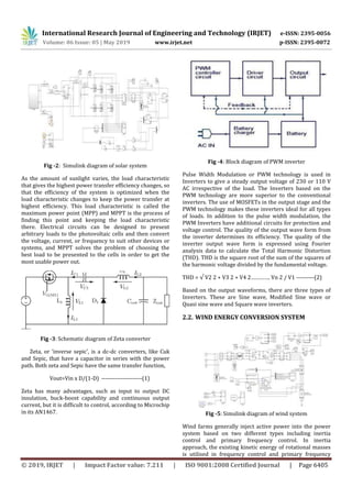
zeta converter is used to boost the voltage level. Inverter is
used before connecting to the load. Similarly wind, battery
and fuel cell are simulated in the same fashion as earlier.
Fig -1: Block diagram of test system
Paper is as follows. In introduction an overview is
given. Solar panel is simulated along with converter and
inverter. Wind energy conversion system is modelled
followed by diesel engine generator and energy storage
units such as battery and fuel energy storage systems.
Initially PI controller is used to attain stability and the
proposed controller is implemented which shows
improved performance which are discussed in the results
section.
2. MODELLING COMPONENTS
2.1. PV ARRAY
Photovoltaic cells are connected electrically in
series and/or parallel circuits to produce higher voltages,
currents and power levels. Photovoltaic modules consist of
PV cell circuits sealed in an environmentally protective
laminate, and are the fundamental building blocks of PV
systems. Photovoltaic panels include one or more PV
modules assembled as a pre-wired, field-installable unit. A
photovoltaic array is the complete power-generating unit,
consisting of any number of PV modules and panels.
The performance of PV modules and arrays are generally
rated according to their maximum DC power output
(watts) under Standard Test Conditions (STC). Standard
Test Conditions are defined by a module (cell) operating
temperature of 25o C (77o F), and incident solar
irradiance level of 1000 W/m2 and under Air Mass 1.5
spectral distribution. Since these conditions are not
always typical of how PV modules and arrays operate in
the field, actual performance is usually 85 to 90 percent of
the STC rating.](https://image.slidesharecdn.com/irjet-v6i5894-191014045621/85/IRJET-Frequency-Control-of-Distributed-Generators-in-Microgrid-with-ANFIS-Controller-1-320.jpg)
![International Research Journal of Engineering and Technology (IRJET) e-ISSN: 2395-0056
Volume: 06 Issue: 05 | May 2019 www.irjet.net p-ISSN: 2395-0072
© 2019, IRJET | Impact Factor value: 7.211 | ISO 9001:2008 Certified Journal | Page 6404
Frequency Control of Distributed Generators in Microgrid with
ANFIS Controller
K. Hema1, P. Maruthupandi2
1M.E II year, Department of EEE, Government College Technology, Coimbatore, India
2Assistant Professor, Department of EEE, Government College Technology, Coimbatore, India
---------------------------------------------------------------------***----------------------------------------------------------------------
Abstract - Frequency deviation is the major problem in
microgrid due to the varying power output from the
renewable energy sources. In this paper, solar and wind are
taken as prime source of power. Since the renewables lack
inertia diesel-generator is used to provide inertia to the
system and energy storage devices are used. The proposed
controller has less settling time compared to the
conventional controllers. Artificial neuro-fuzzy inference
system (ANFIS) controller combines the features of fuzzy
and neural and has improved performance where the fuzzy
rules modify the network according to the power output.
The results are obtained using MATLAB/Simulink model.
Key Words: renewables, frequency deviation, settling
time, fuzzy, ANFIS.
1. INTRODUCTION
A hybrid energy system might consist of various
renewable energy conversion component like wind
turbine, PV array and hydro turbines as well as
conventional non-renewable generators like diesel
generators, and storage devices. To overcome the
incredible power crisis in the country, the best way is to
make use of renewable energy sources. It is inexhaustible
and non-polluting. It has the advantages of low running
and maintenance cost and also noiseless operation.
The voltage power characteristic of a photovoltaic (PV)
array is nonlinear and time varying because of the changes
caused by the atmospheric conditions [1]. When the solar
radiation and temperature varies, the output power of the
PV module is also getting changed. But to get the
maximum efficiency of the PV module it must be operated
at maximum point,so it is necessary to operate the PV
module at its maximum power point for all irradiance and
temperature conditions[2]. To obtain maximum power
from photovoltaic array, photovoltaic power system
usually requires maximum power point tracking
controller (MPPT).
Block diagram of the microgrid is shown in fig.1. Here
Solar, wind, diesel are used as prime source of power
production and energy storage devices such as battery and
fuel cell are used. The power produced from PV array is
varying according to irradiance and temperature hence a
zeta converter is used to boost the voltage level. Inverter is
used before connecting to the load. Similarly wind, battery
and fuel cell are simulated in the same fashion as earlier.
Fig -1: Block diagram of test system
Paper is as follows. In introduction an overview is
given. Solar panel is simulated along with converter and
inverter. Wind energy conversion system is modelled
followed by diesel engine generator and energy storage
units such as battery and fuel energy storage systems.
Initially PI controller is used to attain stability and the
proposed controller is implemented which shows
improved performance which are discussed in the results
section.
2. MODELLING COMPONENTS
2.1. PV ARRAY
Photovoltaic cells are connected electrically in
series and/or parallel circuits to produce higher voltages,
currents and power levels. Photovoltaic modules consist of
PV cell circuits sealed in an environmentally protective
laminate, and are the fundamental building blocks of PV
systems. Photovoltaic panels include one or more PV
modules assembled as a pre-wired, field-installable unit. A
photovoltaic array is the complete power-generating unit,
consisting of any number of PV modules and panels.
The performance of PV modules and arrays are generally
rated according to their maximum DC power output
(watts) under Standard Test Conditions (STC). Standard
Test Conditions are defined by a module (cell) operating
temperature of 25o C (77o F), and incident solar
irradiance level of 1000 W/m2 and under Air Mass 1.5
spectral distribution. Since these conditions are not
always typical of how PV modules and arrays operate in
the field, actual performance is usually 85 to 90 percent of
the STC rating.](https://image.slidesharecdn.com/irjet-v6i5894-191014045621/75/IRJET-Frequency-Control-of-Distributed-Generators-in-Microgrid-with-ANFIS-Controller-1-2048.jpg)
![International Research Journal of Engineering and Technology (IRJET) e-ISSN: 2395-0056
Volume: 06 Issue: 05 | May 2019 www.irjet.net p-ISSN: 2395-0072
© 2019, IRJET | Impact Factor value: 7.211 | ISO 9001:2008 Certified Journal | Page 6406
control exploits the injected power to provide an
appropriate frequency response using pitch angle
controller as shown in fig.5
2.3 Diesel engine generator
Fig-6: Simulink diagram of diesel engine generator
A diesel generator is the blend of a diesel motor with an
electric generator (regularly an alternator) to produce
electrical energy. This is a particular instance of motor
generator. A diesel pressure start motor frequently is
intended to keep running on fuel oil, yet a few sorts are
adjusted for other liquid fuels or natural gas. Diesel
generating sets are utilized as a part of spots without
connection with a power grid, or as emergency
powersupply if the grid fails, and also for more complex
applications, for example, peak-lopping, grid support and
fare to the power grid.
2.4 Battery energy storage system
Fig-7: Simulink diagram of battery energy storage
system.
Battery system comprises of cells which have a qualities
working voltage and most extreme current potential.
Dominant part of battery energy storages system have
control power system that handle electricity from the
battery and makes it suitable for AC loads. This including
changing the current and voltages to maximize the power
output, coordinating the changed over AC power to AC
electrical system and goes to the end current flow out of
the system into grid during outages. The change from DC
to AC power in power conditioning system is finished by
an inverter.
2.5 Fuel energy storage system
Fig-8: Simulink diagram of fuel energy storage system
Hydrogen fuel cell (HFC) fascinates academics and
industrialists because it is suitable for emission-free
electricity generation and can be applicable in distributed
generation to the automobile industry. When burned, HFC
releases water vapor only into the environment. HFC
burns faster and contains considerable chemical energy
per mass (142 MJ) compared with other hydrocarbon
fuels. HFC has high energy density by weight and low
energy density by volume. The environmental impact of
hydrogen storage is desirable, which leads governments
across the globe to enhance the prospects of the hydrogen
economy.
3. Proposed Controller
First Fuzzy logic controller based on Mamdani
inference system is designed for given power system
problem. The input and output data so obtained is utilized
as training and testing data. Later adaptive neuro fuzzy
system is designed. ANFSEDIT toolbox is used to generate
ANFIS.fis file in MATLAB software. Training and testing
data is utilized to train and test the adaptive neuro fuzzy
system. Detail steps of designing of ANFIS can be found in
literature [3]. Briefly, the first layer in ANFIS structure
performs fuzzy formation and second layer performs fuzzy
AND and fuzzy rules. The third layer performs the
normalization of the membership functions and the fourth
layer is the conclusive part of fuzzy rules and finally, the
last layer calculates the network output. According to
these, it is obvious that the first and fourth layers in ANFIS
structure are adaptive layers in which Ci and σi in layer 1
are known as premise parameters that are related to
membership function of fuzzy input. In layer 4 ri, qi and pi](https://image.slidesharecdn.com/irjet-v6i5894-191014045621/85/IRJET-Frequency-Control-of-Distributed-Generators-in-Microgrid-with-ANFIS-Controller-3-320.jpg)
![International Research Journal of Engineering and Technology (IRJET) e-ISSN: 2395-0056
Volume: 06 Issue: 05 | May 2019 www.irjet.net p-ISSN: 2395-0072
© 2019, IRJET | Impact Factor value: 7.211 | ISO 9001:2008 Certified Journal | Page 6408
Fig-14: Frequency plot using ANFIS controller
5. Conclusion
The results are obtained using MATLAB/Simulation.
Initially only the sources are connected without any
external inertia .PI controller has higher settling time
(0.3S) as shown in fig12. Then diesel engine generator is
added to the system and shows settling time
comparatively less (0.1S).Finally the proposed ANFIS
controller is used and frequency stability is achieved at
0.08S and it is superior to other controllers as shown in
fig14.The work undertaken is for standalone microgrid
and futher it may be modified as an islanded microgrid or
grid connected microgrid.
REFERENCES
[1] Ansari, S. Chaterjee, and A. Iqbal, “Fuzzy logic
control scheme for solar photo voltaic system for
maximum power point tracker,” Int. J Sustain.
Energy, vol. 29, no. 4, pp. 245–255, Apr. 2010.
[2] E. Kremers, P. Viejo, O. Barambones and J. G. d.
Durana, "A Complex Systems Modelling Approach
for Decentralised Simulation of Electrical
Microgrids," 2010 15th IEEE International
Conference on Engineering of Complex Computer
Systems, Oxford, 2010, pp. 302-311.
[3] Bevrani, H., Daneshmand, P.R.: ‘Fuzzy logic-based
load frequency control concerning high
penetration of wind turbine’, IEEE Syst. J., 2012, 6,
(1), pp.173–180.
[4] Cam, E.: ‘Application of fuzzy logic for load
frequency control of hydro electrical power
plants’, Energy Convers. Manage., 2007, 48, pp.
1281–1288.
[5] T. L. Kottas, Y. S. Boutalis, and A. D. Karlis, “New
maximum power tracker for PV arrays using fuzzy
controller in close cooperation with fuzzy
cognitive networks,” IEEE Trans. Energy Convers.,
vol. 21.
[6] Hassan Bevrani, Fuzzy Logic-Based Load-
Frequency Control Concerning High Penetration
of Wind Turbines, IEEE SYSTEMS JOURNAL, Vol.
6, no. 1, March 2012.
[7] A.A. Salarn, A. Moharned, and M. A. Hannan, "
Technical challenges on Microgrids,"Asian
Research Publishing Network (ARPN), vol. 3, no.
6, pp. 64-69, Dec. 2008.
[8] M. S. Mahmoud, M. Saif Ur Rahman and F. M. A. L. -
Sunni, "Review of microgrid architectures – a
system of systems perspective," in IET Renewable
Power Generation, vol. 9, no. 8, pp. 1064-1078, 11
2015.
[9] Ngamroo I, “Robust frequency control of wind–
diesel hybrid power system using
superconducting magnetic energy storage”. Int J
Emerg Electr Power Syst 2009;10(2).
[10]I.Serban and C. Marinescu, “Aggregate load-
frequency control of a wind-hydro autonomous
microgrid,” Renew. Energy, vol. 36, no. 12, pp.
3345–3354, 2011.
[11]H. Bevrani, “Robust load frequency controller in a
deregulated environment: A mu;-synthesis
approach,” in Proc. IEEE Int. Conf. Control Appl.,
1999, vol. 1, pp. 616–621.](https://image.slidesharecdn.com/irjet-v6i5894-191014045621/85/IRJET-Frequency-Control-of-Distributed-Generators-in-Microgrid-with-ANFIS-Controller-5-320.jpg)

This document describes a microgrid system with distributed generators including solar panels, wind turbines, and a diesel generator. Energy storage devices like batteries and fuel cells are also included. Frequency control of the system is challenging due to varying renewable energy output. The document proposes using an Artificial Neuro-Fuzzy Inference System (ANFIS) controller to improve frequency control performance compared to conventional controllers like PI. MATLAB/Simulink models are developed to simulate the microgrid components and evaluate the ANFIS controller.


