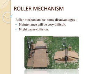
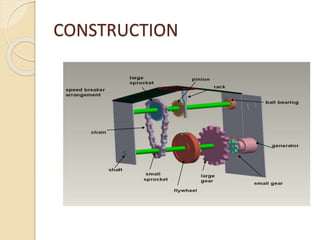
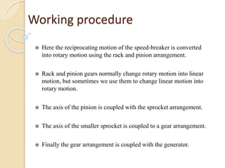
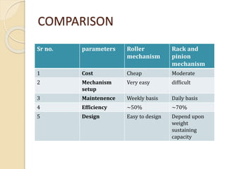
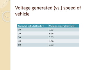
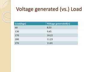
WELCOME
POWER GENERATION USING SPEED
BREAKER
CONTENT
1. Introduction
2. Scope , merits and uses
3. Basic principle
4. Gear
5. Roller mechanism
6. Rack and pinion mechanism
7. Comparison
8. Conclusion
INTRODUCTION
 In our country there is a shortage of electricity
and we try to overcome this problem by non
conventional sources of energy.
 To sort out the energy crises it led to the idea of
generating power using speed breaker.
 A large amount of energy is wasted by the
vehicles due to friction.
 Electricity can be generated using vehicles by its
motion (Kinetic Energy) and weight (Potential
Energy) as an input.
Scope, Merits and Uses
 Low budget electricity production.
 Low floor area and no obstruction to traffic.
 Easy maintenance.
 Energy available through out the year.
 Pollution free power generation.
 No fuel transportation required.
 No need of man power during power
generation.
 More suitable and compact mechanism to
enhance efficiency.
 Uses : Charging batteries and using them
to light up the streets etc.
Basic Principle
 Simple energy conversion from
mechanical to electrical.
 To generate the electricity using the
vehicle’s speed and weight as input.
 Possible using 2 different mechanisms
Roller mechanism
Rack and pinion mechanism
Gear Mechanism
 A mechanism for transmitting motion for some
specific purpose.
 GEAR : A gear is a wheel with teeth on its outer
edge.
 The teeth of one gear engages with the teeth of other.
Gear
 Two meshed gears always rotate in
opposite directions.
 Two gears are of different diameters.
Driven gear
Driver gear
Gear ratio
 Generally, the gear ratio is
calculated by counting the teeth of
the two gears, and applying the
following formula :
Gear ratio = Number of teeth on driven gear
Number of teeth on driver gear
Gear ratio- calculation
 A 100 tooth gear drives a
25 tooth gear . Calculate the
gear ratio of the meshing teeth.
Gear ratio = Number of teeth on driven gear
Number of teeth on driver gear
Gear ratio = driven 25 = 1
driver 100 4
This is written as 1:4
ROLLER MECHANISM
Roller mechanism has some disadvantages :
 Maintenance will be very difficult.
 Might cause collision.
RACK AND PINION MECHANISM
The various equipments are :
 Rack-pinion
 Sprockets
 Gears
 Flywheel
 Dynamo
Rack and pinion- It convert linear motion to
rotational and vice versa
sprocket mechanism-transfer rotary
between two shafts
Flywheel- this is use to regulate the energy and
maintain the energy at an uniform level so that the
shaft rotate at an uniform r.p.m
Dynamo- It is the dc generator which is
use to generate current . Generates current as per
the faraday’s law.
CONSTRUCTION
Working procedure
 Here the reciprocating motion of the speed-breaker is converted
into rotary motion using the rack and pinion arrangement.
 Rack and pinion gears normally change rotary motion into linear
motion, but sometimes we use them to change linear motion into
rotary motion.
 The axis of the pinion is coupled with the sprocket arrangement.
 The axis of the smaller sprocket is coupled to a gear arrangement.
 Finally the gear arrangement is coupled with the generator.
COMPARISON
Sr no. parameters Roller
mechanism
Rack and
pinion
mechanism
1 Cost Cheap Moderate
2 Mechanism
setup
Very easy difficult
3 Maintenence Weekly basis Daily basis
4 Efficiency ~50% ~70%
5 Design Easy to design Depend upon
weight
sustaining
capacity
Voltage generated (vs.) speed of
vehicle
Speed of vehicle(kn/hr) Voltage generated(volts)
10 7.93
20 6.28
30 5.03
40 4.66
50 3.03
Voltage generated (vs.) Load
Load(kgs) Voltage generated(v)
60 8.33
130 9.45
170 10.22
200 11.23
270 11.81
Conclusion
 Power generation does not require any fuel
input and the running cost is very less.
 There are some non- conventional methods of
producing energy. This project is a step to path
of exploring the possibilities of energy from
several non- conventional energy sources.
THANK YOU

power generation from speed breaker

  • 1.
  • 2.
  • 3.
    CONTENT 1. Introduction 2. Scope, merits and uses 3. Basic principle 4. Gear 5. Roller mechanism 6. Rack and pinion mechanism 7. Comparison 8. Conclusion
  • 4.
    INTRODUCTION  In ourcountry there is a shortage of electricity and we try to overcome this problem by non conventional sources of energy.  To sort out the energy crises it led to the idea of generating power using speed breaker.  A large amount of energy is wasted by the vehicles due to friction.  Electricity can be generated using vehicles by its motion (Kinetic Energy) and weight (Potential Energy) as an input.
  • 5.
    Scope, Merits andUses  Low budget electricity production.  Low floor area and no obstruction to traffic.  Easy maintenance.  Energy available through out the year.  Pollution free power generation.  No fuel transportation required.  No need of man power during power generation.  More suitable and compact mechanism to enhance efficiency.  Uses : Charging batteries and using them to light up the streets etc.
  • 6.
    Basic Principle  Simpleenergy conversion from mechanical to electrical.  To generate the electricity using the vehicle’s speed and weight as input.  Possible using 2 different mechanisms Roller mechanism Rack and pinion mechanism
  • 7.
    Gear Mechanism  Amechanism for transmitting motion for some specific purpose.  GEAR : A gear is a wheel with teeth on its outer edge.  The teeth of one gear engages with the teeth of other.
  • 8.
    Gear  Two meshedgears always rotate in opposite directions.  Two gears are of different diameters. Driven gear Driver gear
  • 9.
    Gear ratio  Generally,the gear ratio is calculated by counting the teeth of the two gears, and applying the following formula : Gear ratio = Number of teeth on driven gear Number of teeth on driver gear
  • 10.
    Gear ratio- calculation A 100 tooth gear drives a 25 tooth gear . Calculate the gear ratio of the meshing teeth. Gear ratio = Number of teeth on driven gear Number of teeth on driver gear Gear ratio = driven 25 = 1 driver 100 4 This is written as 1:4
  • 11.
    ROLLER MECHANISM Roller mechanismhas some disadvantages :  Maintenance will be very difficult.  Might cause collision.
  • 12.
    RACK AND PINIONMECHANISM The various equipments are :  Rack-pinion  Sprockets  Gears  Flywheel  Dynamo
  • 13.
    Rack and pinion-It convert linear motion to rotational and vice versa sprocket mechanism-transfer rotary between two shafts Flywheel- this is use to regulate the energy and maintain the energy at an uniform level so that the shaft rotate at an uniform r.p.m Dynamo- It is the dc generator which is use to generate current . Generates current as per the faraday’s law.
  • 14.
  • 15.
    Working procedure  Herethe reciprocating motion of the speed-breaker is converted into rotary motion using the rack and pinion arrangement.  Rack and pinion gears normally change rotary motion into linear motion, but sometimes we use them to change linear motion into rotary motion.  The axis of the pinion is coupled with the sprocket arrangement.  The axis of the smaller sprocket is coupled to a gear arrangement.  Finally the gear arrangement is coupled with the generator.
  • 16.
    COMPARISON Sr no. parametersRoller mechanism Rack and pinion mechanism 1 Cost Cheap Moderate 2 Mechanism setup Very easy difficult 3 Maintenence Weekly basis Daily basis 4 Efficiency ~50% ~70% 5 Design Easy to design Depend upon weight sustaining capacity
  • 17.
    Voltage generated (vs.)speed of vehicle Speed of vehicle(kn/hr) Voltage generated(volts) 10 7.93 20 6.28 30 5.03 40 4.66 50 3.03
  • 18.
    Voltage generated (vs.)Load Load(kgs) Voltage generated(v) 60 8.33 130 9.45 170 10.22 200 11.23 270 11.81
  • 19.
    Conclusion  Power generationdoes not require any fuel input and the running cost is very less.  There are some non- conventional methods of producing energy. This project is a step to path of exploring the possibilities of energy from several non- conventional energy sources.
  • 20.