The document provides information about various types of instruments used to measure electrical quantities like current, voltage, power, and temperature. It discusses the definitions, principles, constructions, and workings of galvanometers, voltmeters, ammeters, wattmeters, dynamometers, energy meters, and thermoelectric instruments. The key points are:
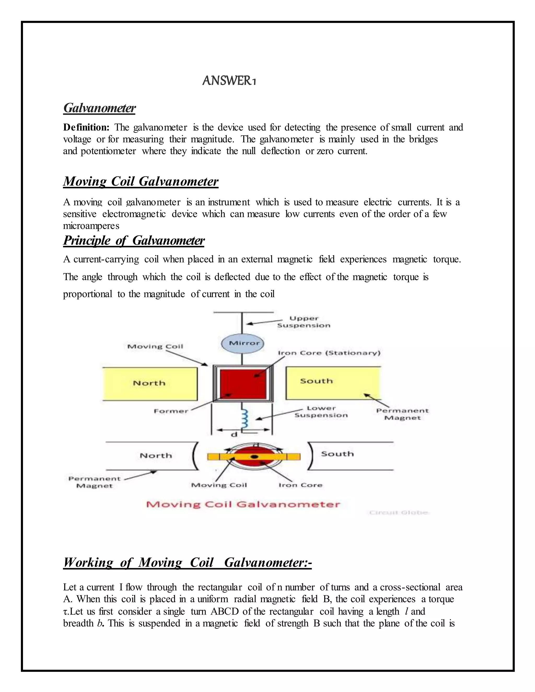
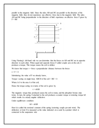
- Galvanometers measure small currents using the magnetic torque produced when a current-carrying coil is placed in a magnetic field.
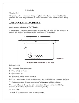
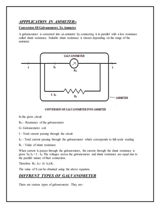
- Instruments can be converted to voltmeters and ammeters by connecting galvanometers in series with high resistances or in parallel with low resistances, respectively.
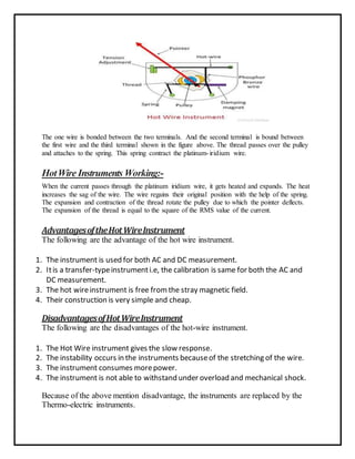
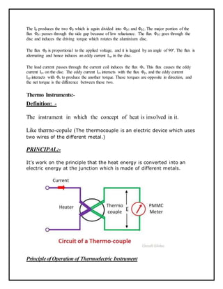
- Hot-wire instruments use expansion of a wire due to heating by current