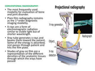
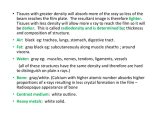
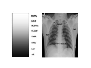
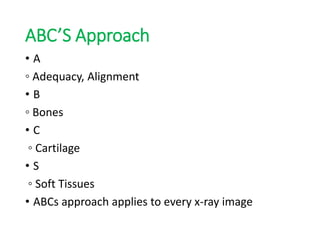
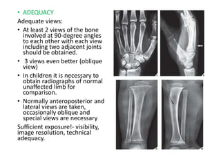
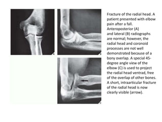
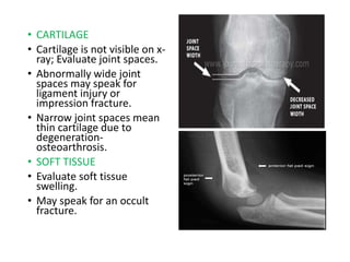
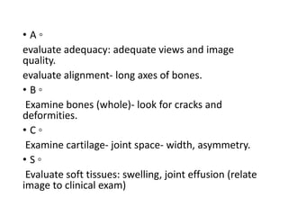
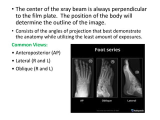
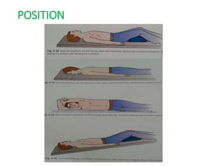
Radiology plays an important role in orthopaedics by providing diagnostic images of bones, joints, and soft tissues. The document discusses various imaging techniques used including conventional radiography, CT, MRI, ultrasound and others. It focuses on conventional radiography, describing the ABCs approach to evaluating x-rays which includes assessing adequacy, alignment, bones, cartilage, and soft tissues. Numerous orthopaedic views are outlined including those for the shoulder, elbow, wrist and their clinical applications. Standard projections and variations that demonstrate specific anatomical structures are presented.


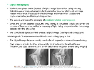
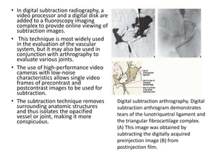
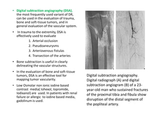

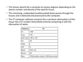


![ONFH[AVN HIP] -TRIPLE REGIME -A NOVAL SURGICAL CONCEPT .pptx](https://cdn.slidesharecdn.com/ss_thumbnails/onfhavnhip2026koaconcalicutdrgokuldevdrmashraf-260210064517-213ec005-thumbnail.jpg?width=640&height=640&fit=bounds)

![CTEV [ clubfoot] DR ARUN LAL ,DR MOHAMED ASHRAF travancore medical college k...](https://cdn.slidesharecdn.com/ss_thumbnails/ctevclubfootdrarunlaldrmohamedashraftravancoremedicalcollegekollamkeralaindia-260208063247-18fc466c-thumbnail.jpg?width=640&height=640&fit=bounds)


