Introduction
General aspects
• Ainduction machine can be used as either a
• induction generator or an induction motor.
• Induction motors are popularly used in the
industry
• Focus on three-phase induction motor
• Main features: cheap and low maintenance
• Main disadvantages: speed control is not easy
2
3.
Induction Motor
•Why inductionmotor (IM)?
–Robust; No brushes. No contacts on rotor shaft
–High Power/Weight ratio compared to DC motor
–Lower Cost/Power
–Easy to manufacture
–Almost maintenance-free, except for bearing and
other mechanical parts
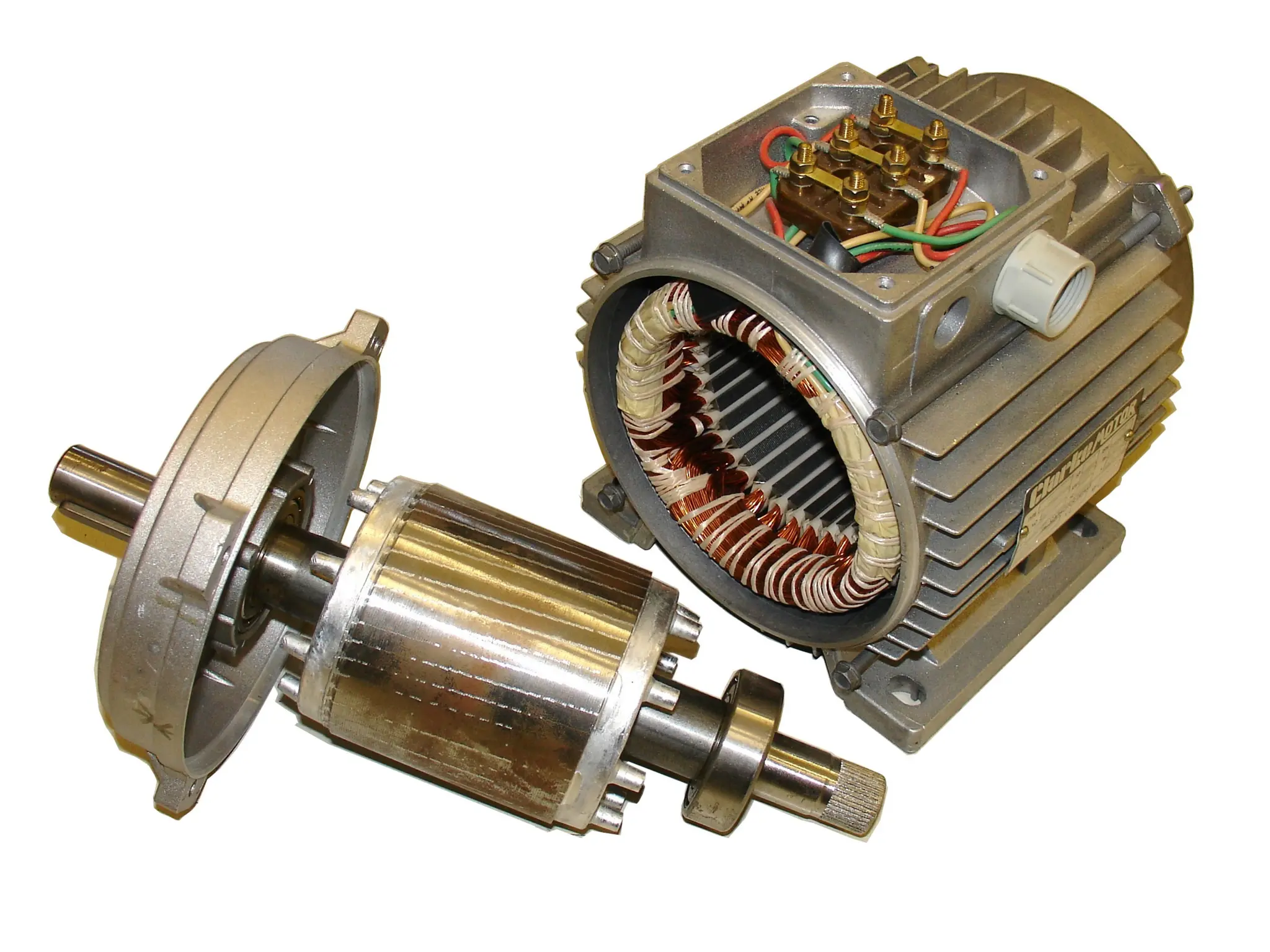
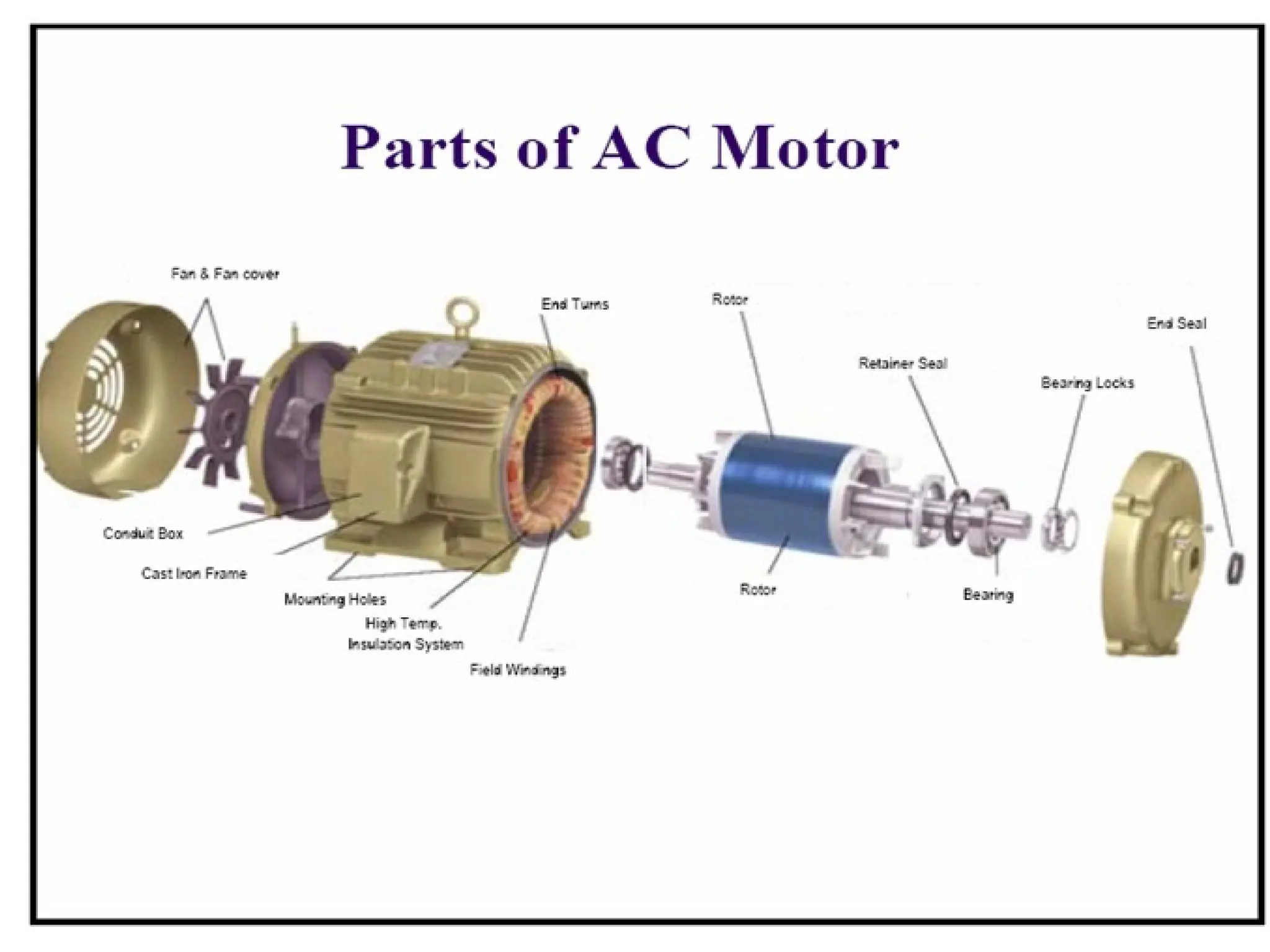
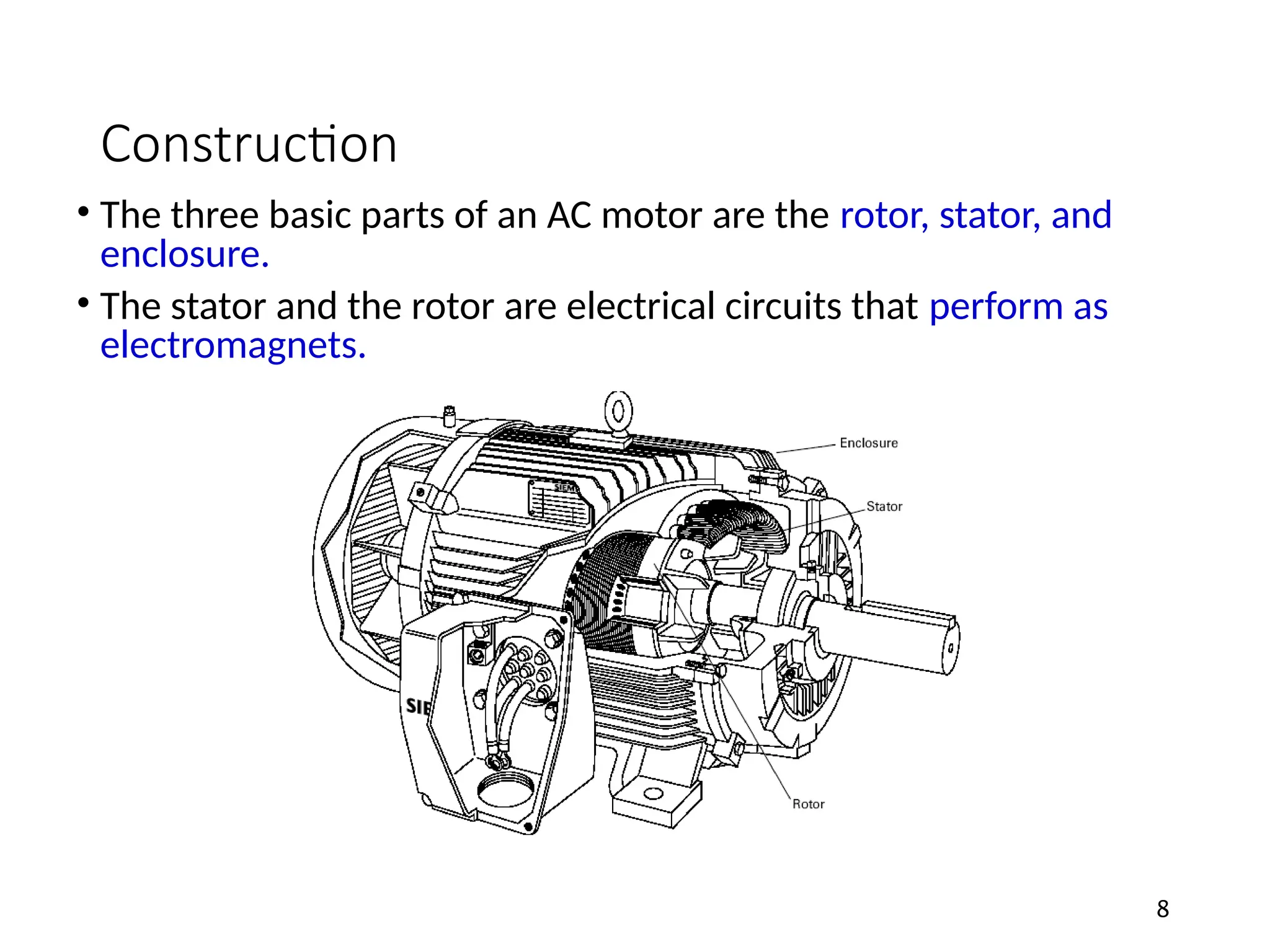
Construction
• The threebasic parts of an AC motor are the rotor, stator, and
enclosure.
• The stator and the rotor are electrical circuits that perform as
electromagnets.
8
9.
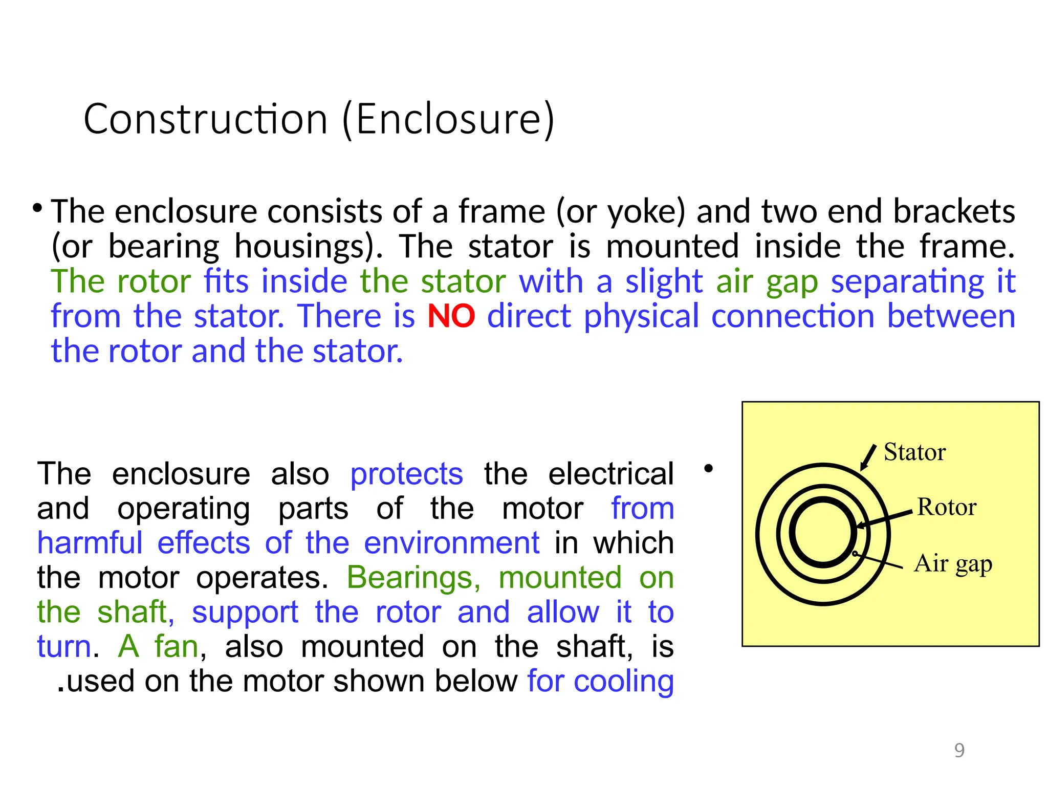
Construction (Enclosure)
• Theenclosure consists of a frame (or yoke) and two end brackets
(or bearing housings). The stator is mounted inside the frame.
The rotor fits inside the stator with a slight air gap separating it
from the stator. There is NO direct physical connection between
the rotor and the stator.
9
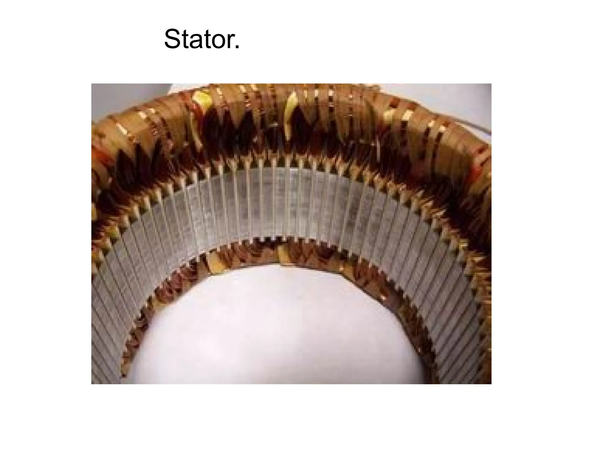
Stator
Rotor
Air gap
•
The enclosure also protects the electrical
and operating parts of the motor from
harmful effects of the environment in which
the motor operates. Bearings, mounted on
the shaft, support the rotor and allow it to
turn. A fan, also mounted on the shaft, is
used on the motor shown below for cooling
.
10.
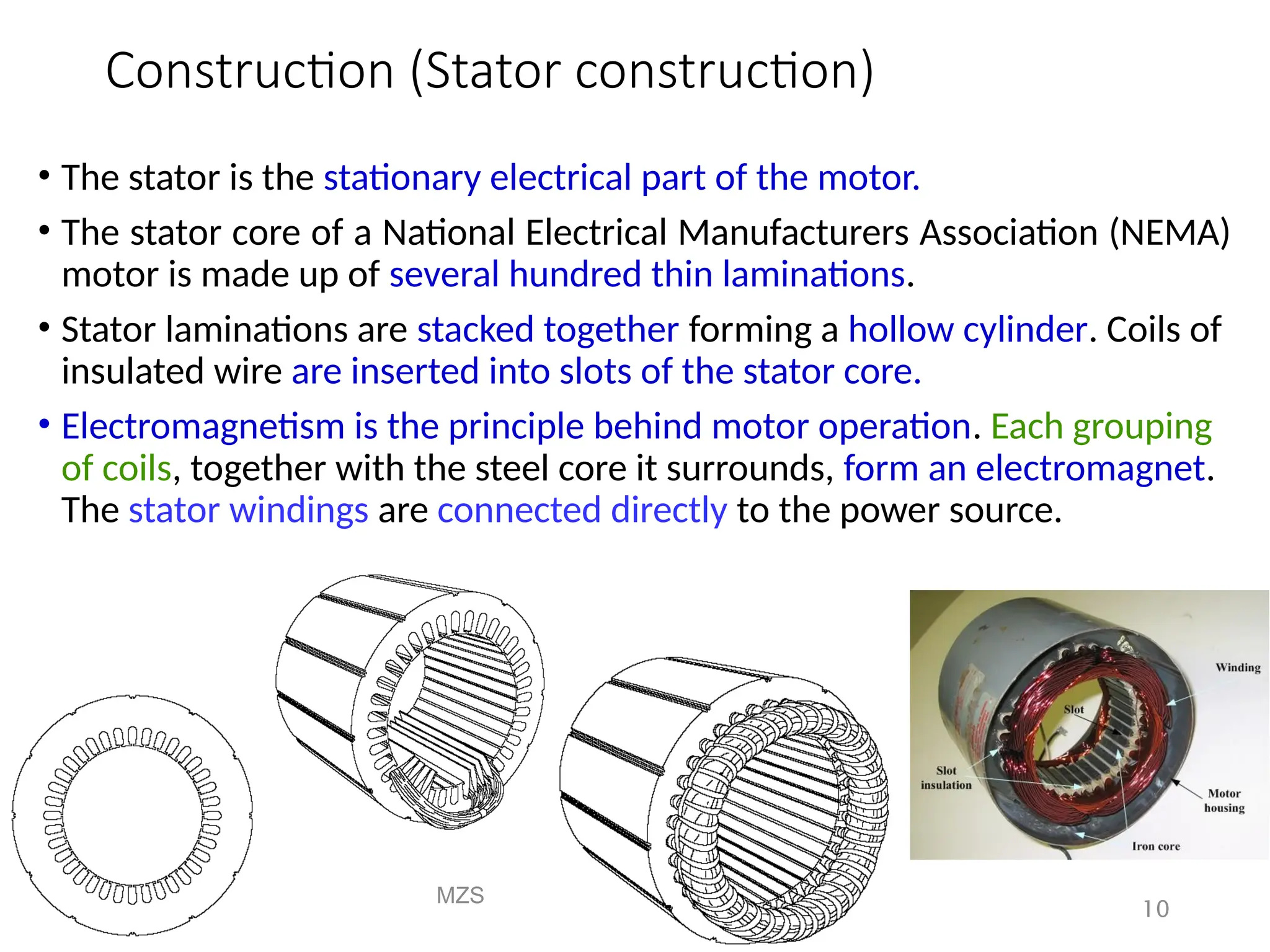
Construction (Stator construction)
•The stator is the stationary electrical part of the motor.
• The stator core of a National Electrical Manufacturers Association (NEMA)
motor is made up of several hundred thin laminations.
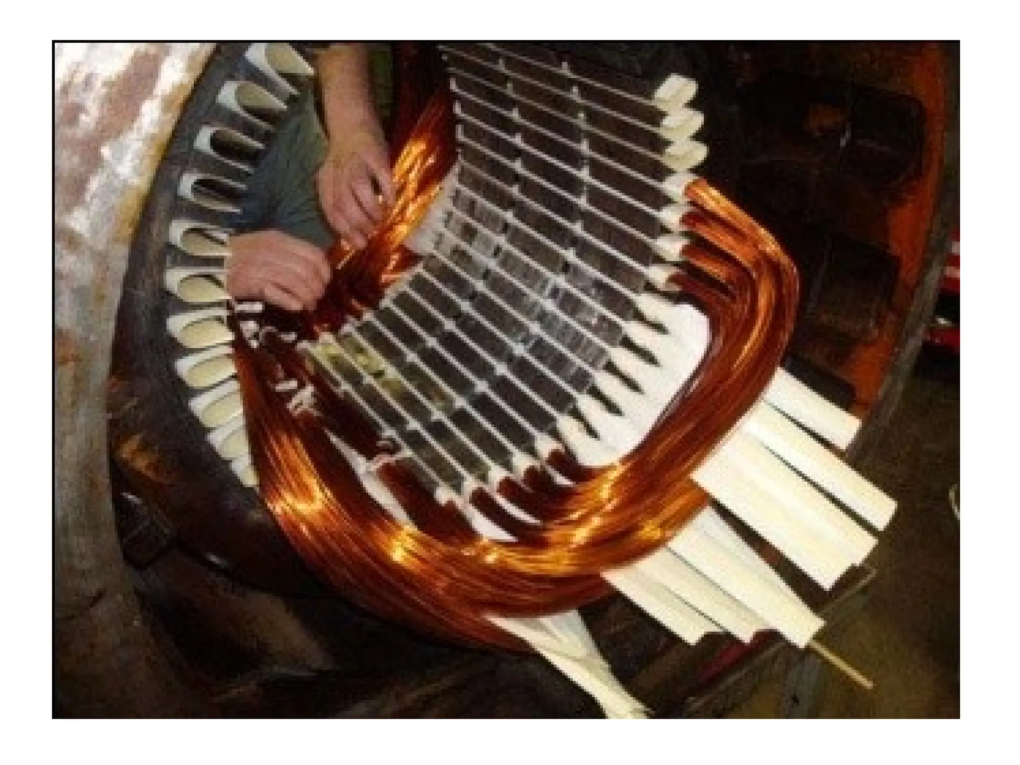
• Stator laminations are stacked together forming a hollow cylinder. Coils of
insulated wire are inserted into slots of the stator core.
• Electromagnetism is the principle behind motor operation. Each grouping
of coils, together with the steel core it surrounds, form an electromagnet.
The stator windings are connected directly to the power source.
MZS
FKEE, UMP
10
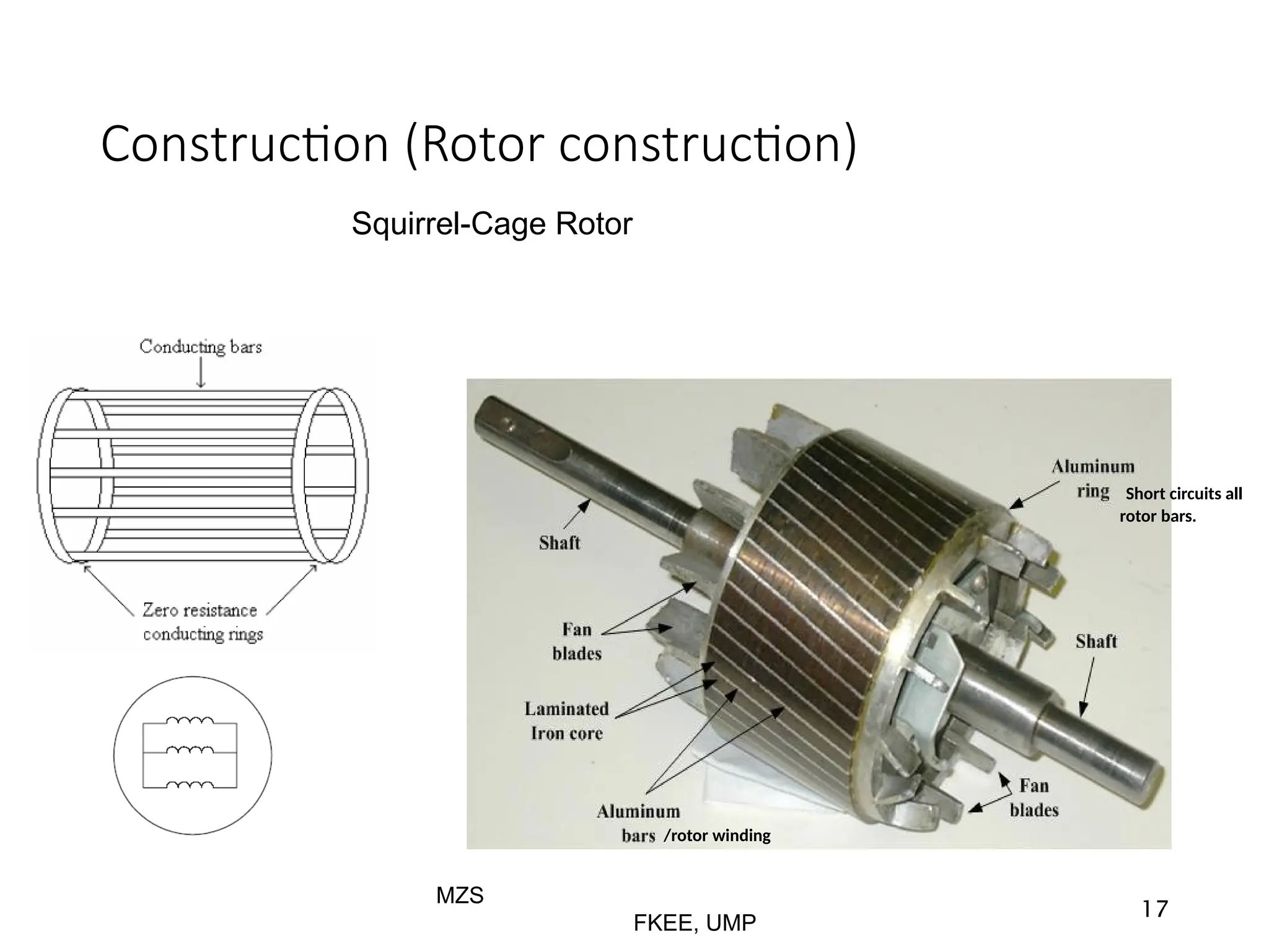
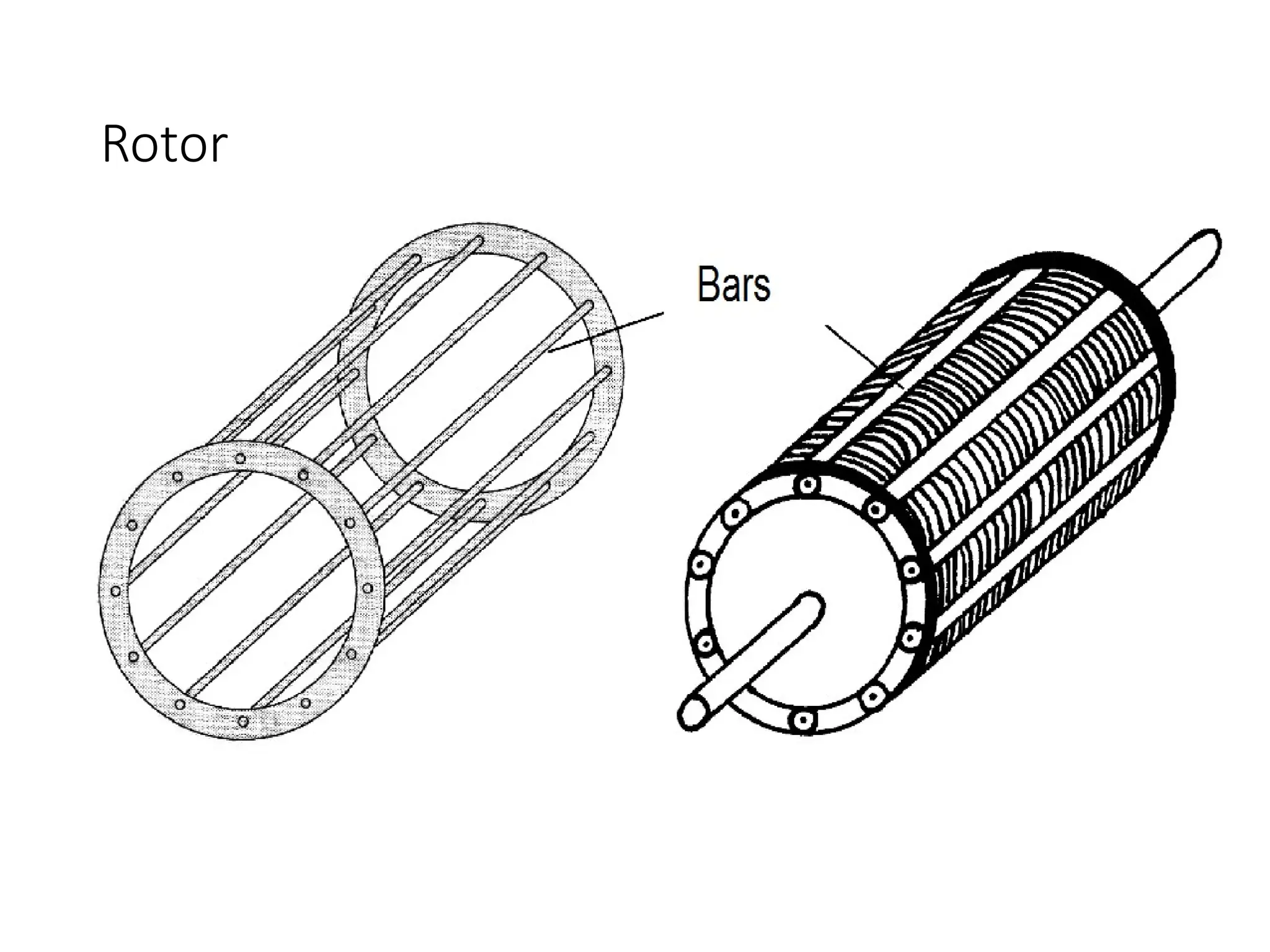
Construction (Rotor construction)
•The rotor is the rotating part of the electromagnetic circuit.
• It can be found in two types:
• Squirrel cage
• Wound rotor
• However, the most common type of rotor is the “squirrel
cage” rotor.
13
14.
Construction (Rotor construction)
•Induction motor types:
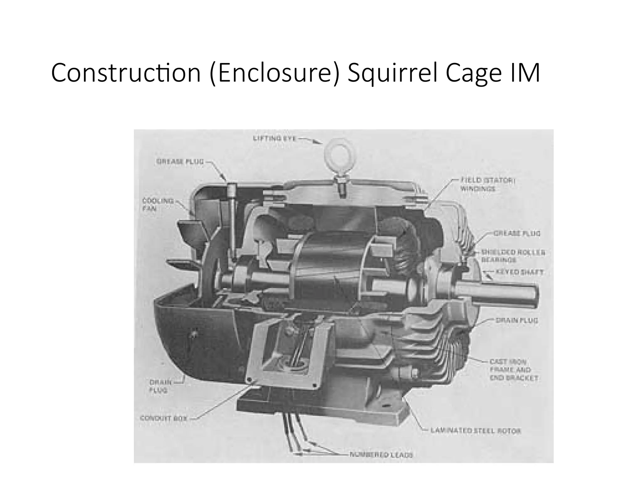
Squirrel cage type:
Rotor winding is composed of copper bars embedded in the rotor slots
and shorted at both end by end rings
Simple, low cost, robust, low maintenance
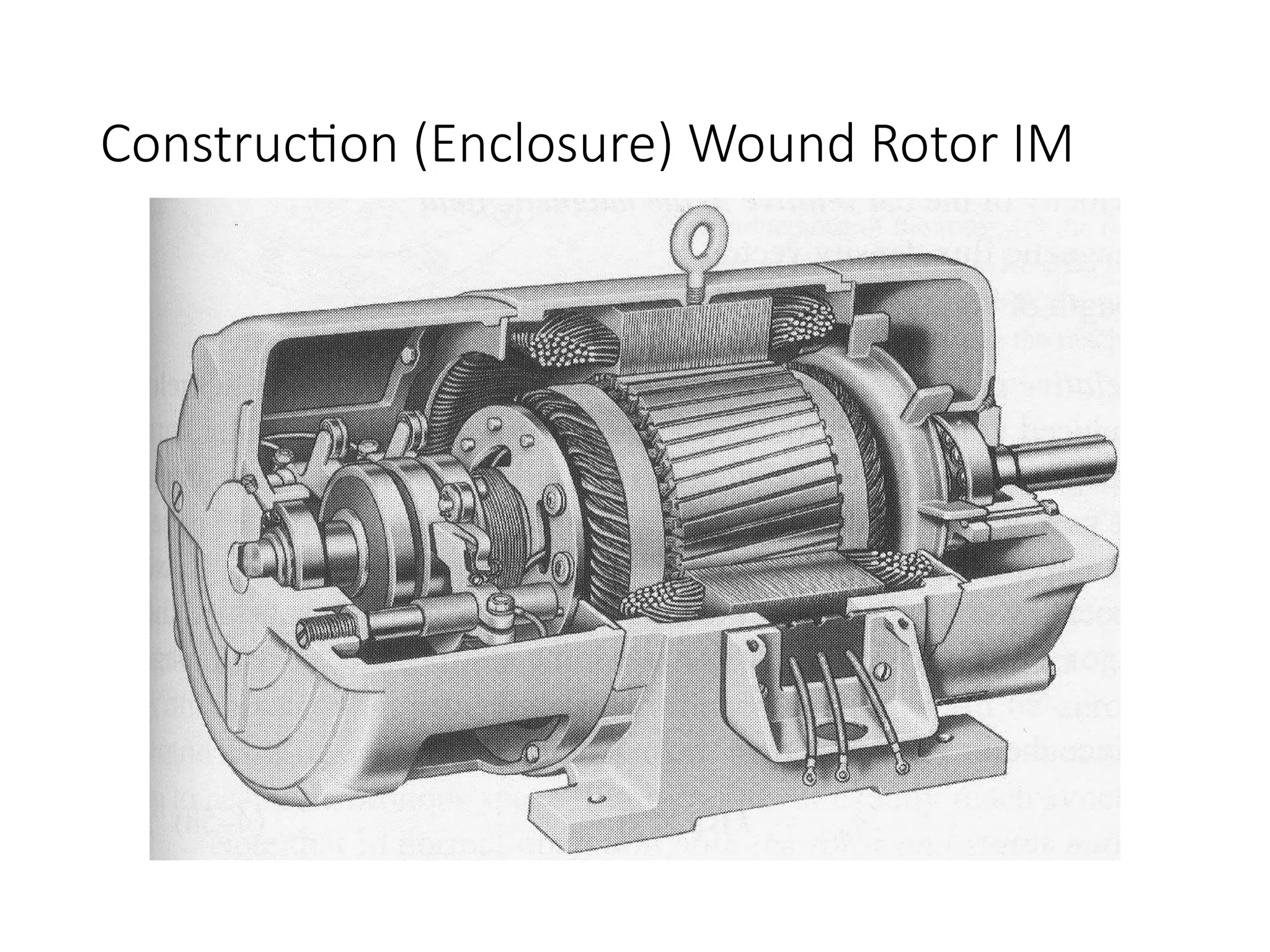
Wound rotor type:
Rotor winding is wound by wires. The winding terminals can be
connected to external circuits through slip rings and brushes.
Easy to control speed, more expensive.
14
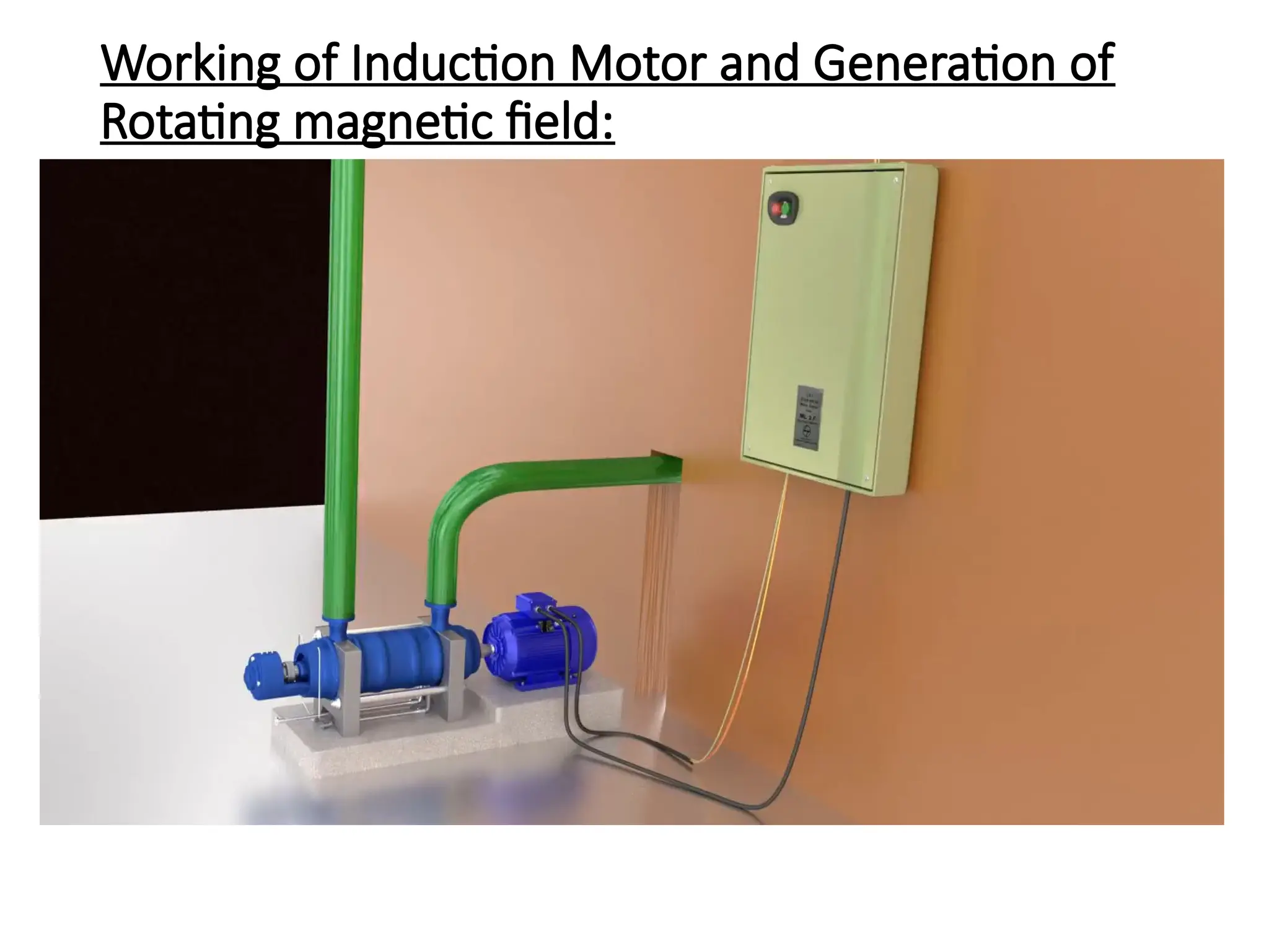
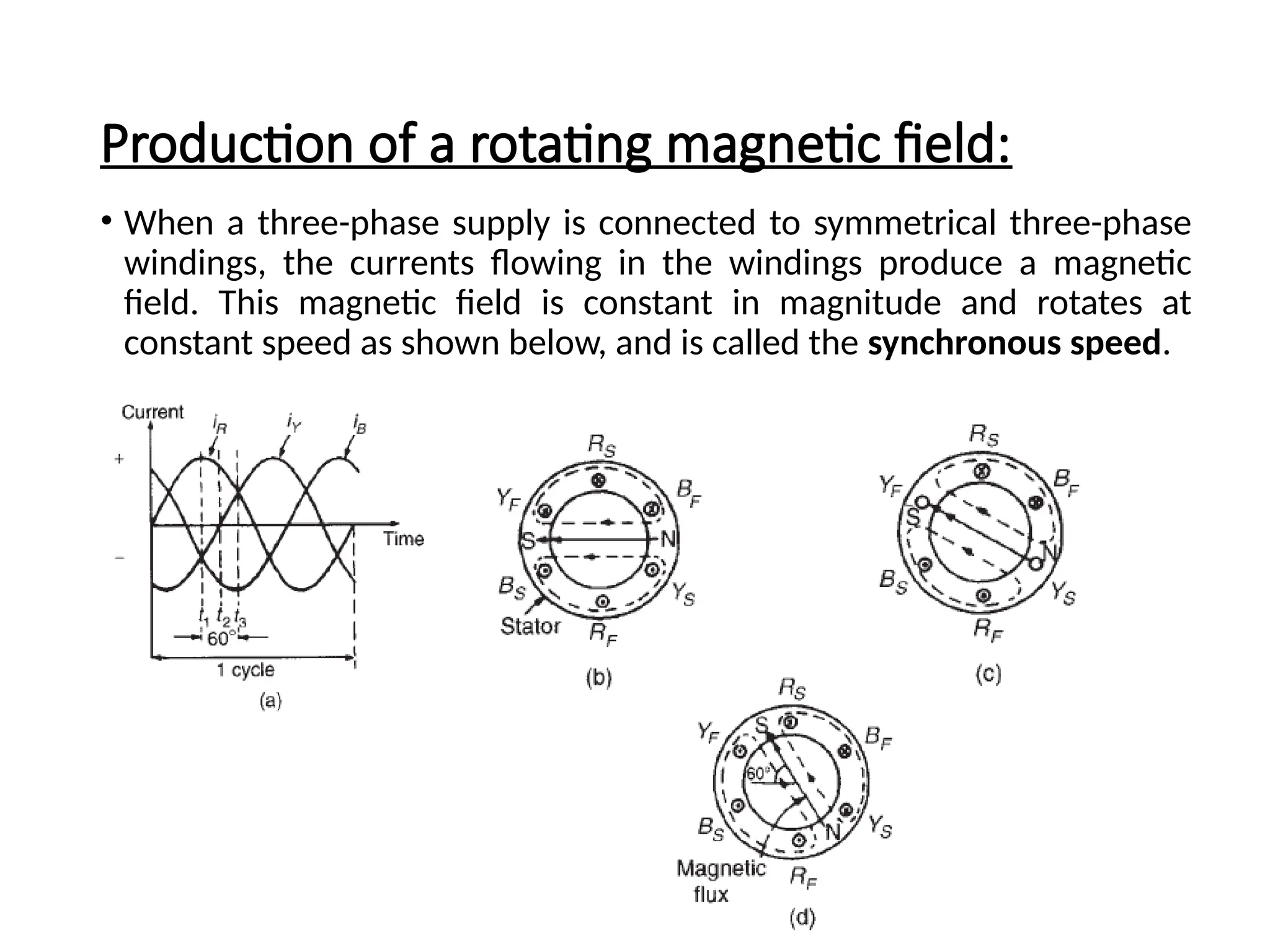
Production of arotating magnetic field:
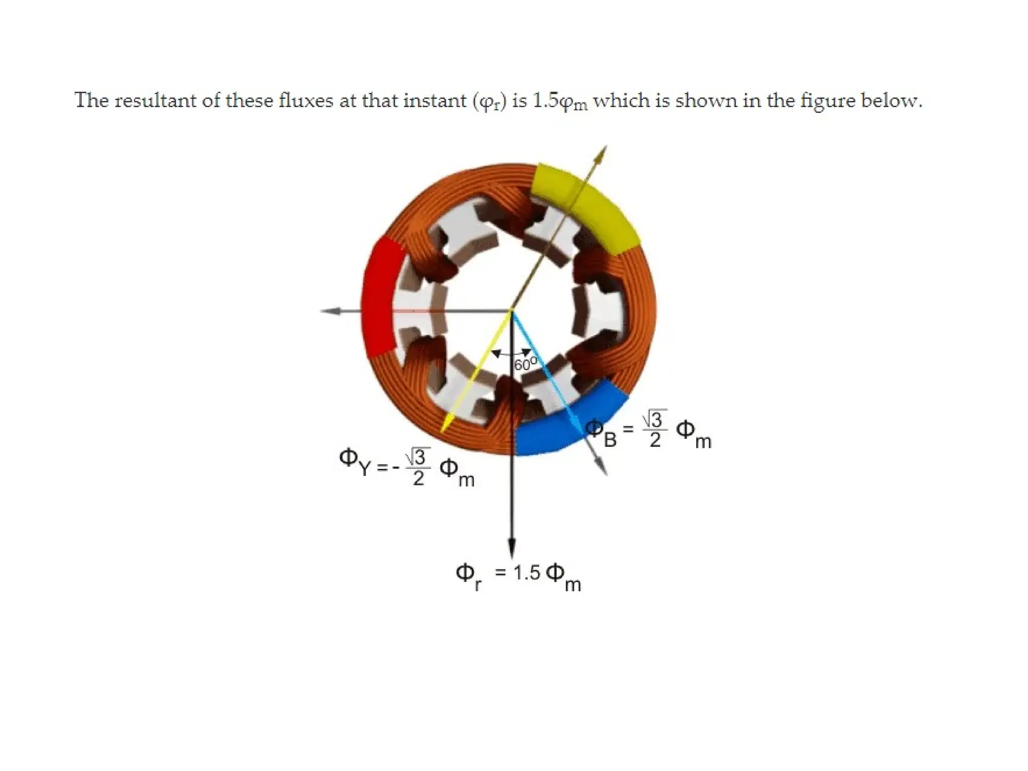
• When a three-phase supply is connected to symmetrical three-phase
windings, the currents flowing in the windings produce a magnetic
field. This magnetic field is constant in magnitude and rotates at
constant speed as shown below, and is called the synchronous speed.
20.
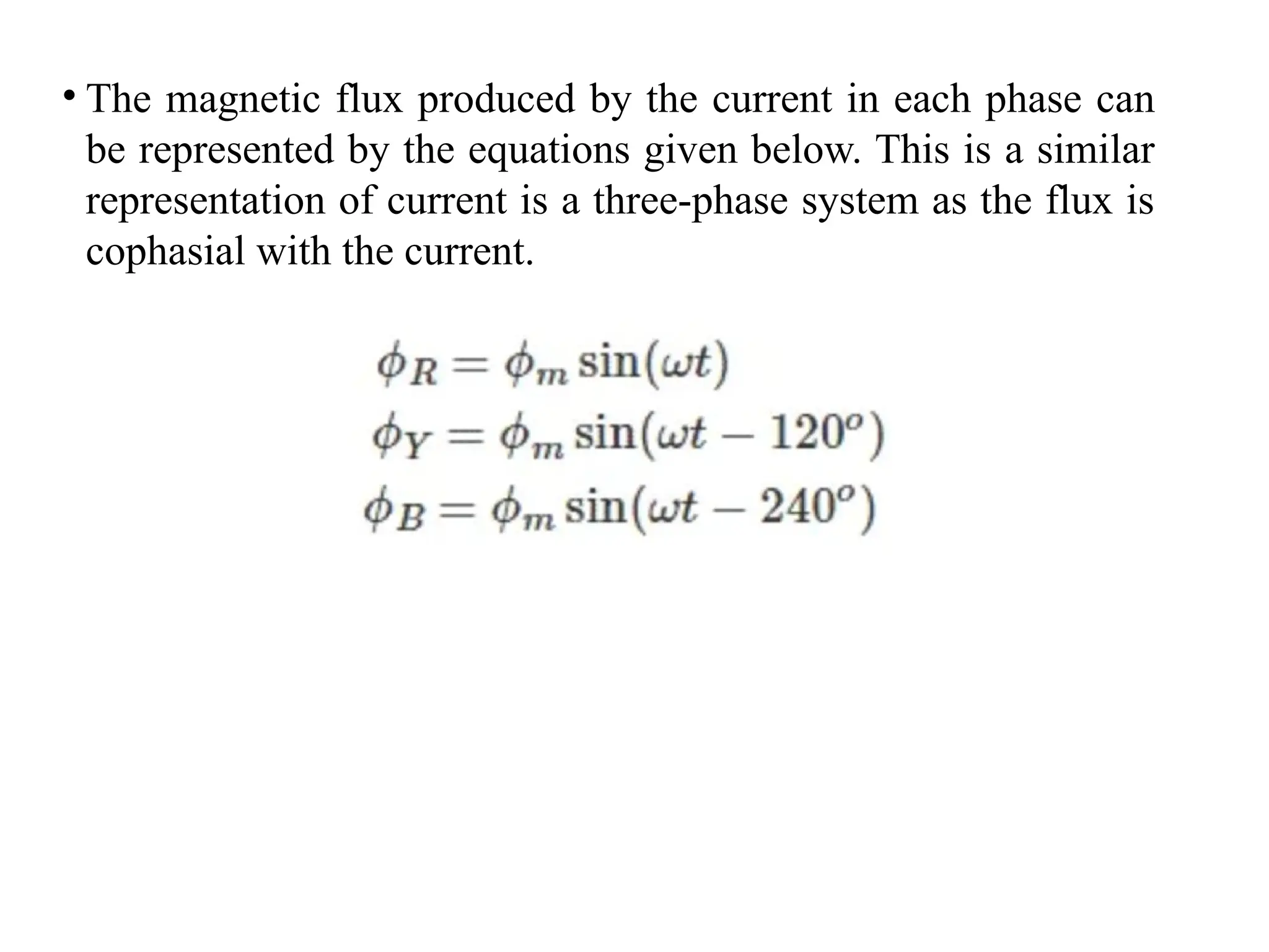
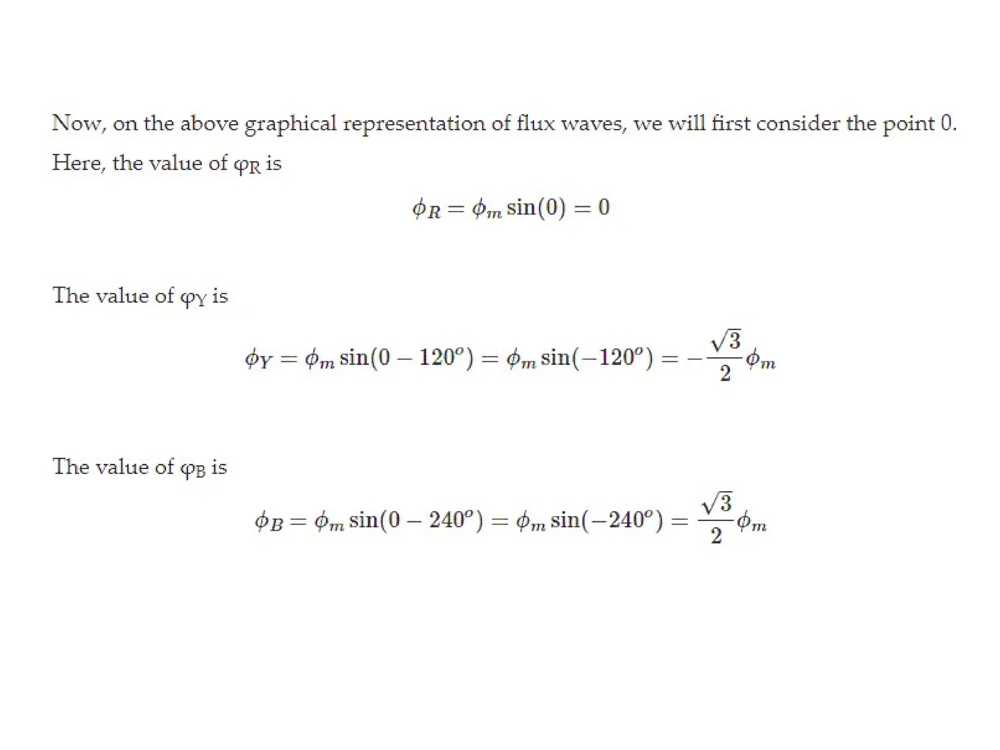
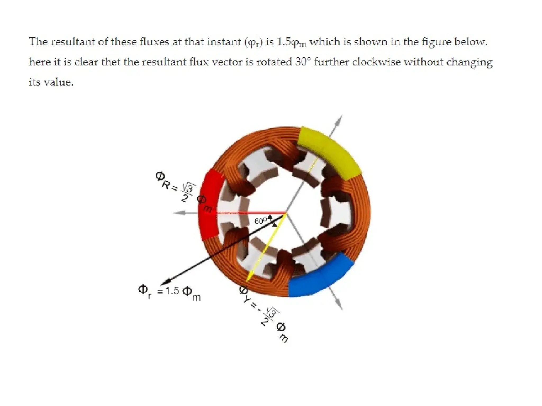
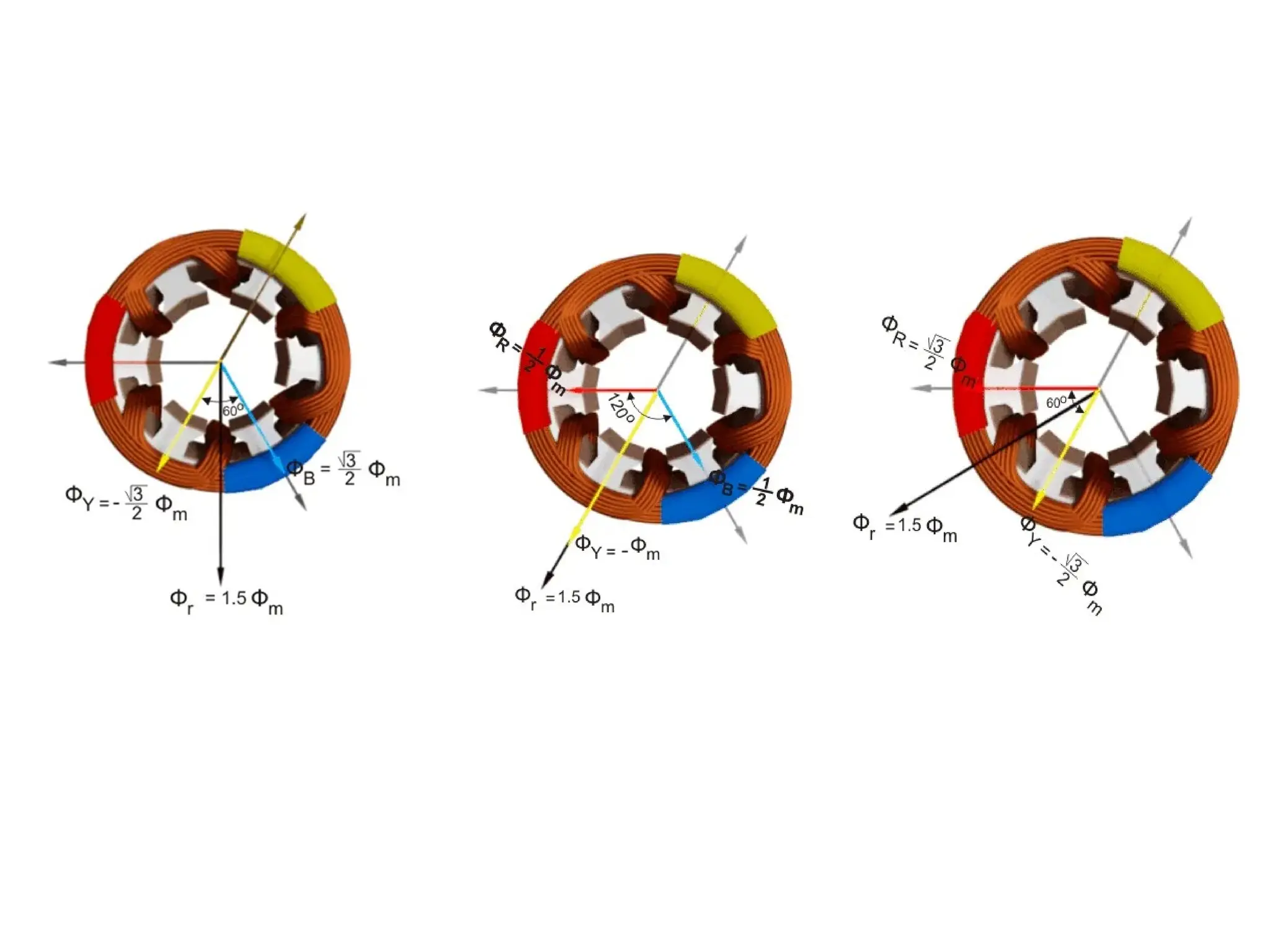
• The magneticflux produced by the current in each phase can
be represented by the equations given below. This is a similar
representation of current is a three-phase system as the flux is
cophasial with the current.
27.
Principle of operationof a three-phase
induction motor:
• When a three-phase supply is connected to the stator windings, a
rotating magnetic field is produced. As the magnetic flux cuts a bar
on the rotor, an e.m.f. is induced in it and since it is joined, via the
end conducting rings, to another bar one pole pitch away, a current
flows in the bars. The magnetic field associated with this current
flowing in the bars interacts with the rotating magnetic field and a
force is produced, tending to turn the rotor in the same direction as
the rotating magnetic field. Similar forces are applied to all the
conductors on the rotor, so that a torque is produced causing the
rotor to rotate.
28.
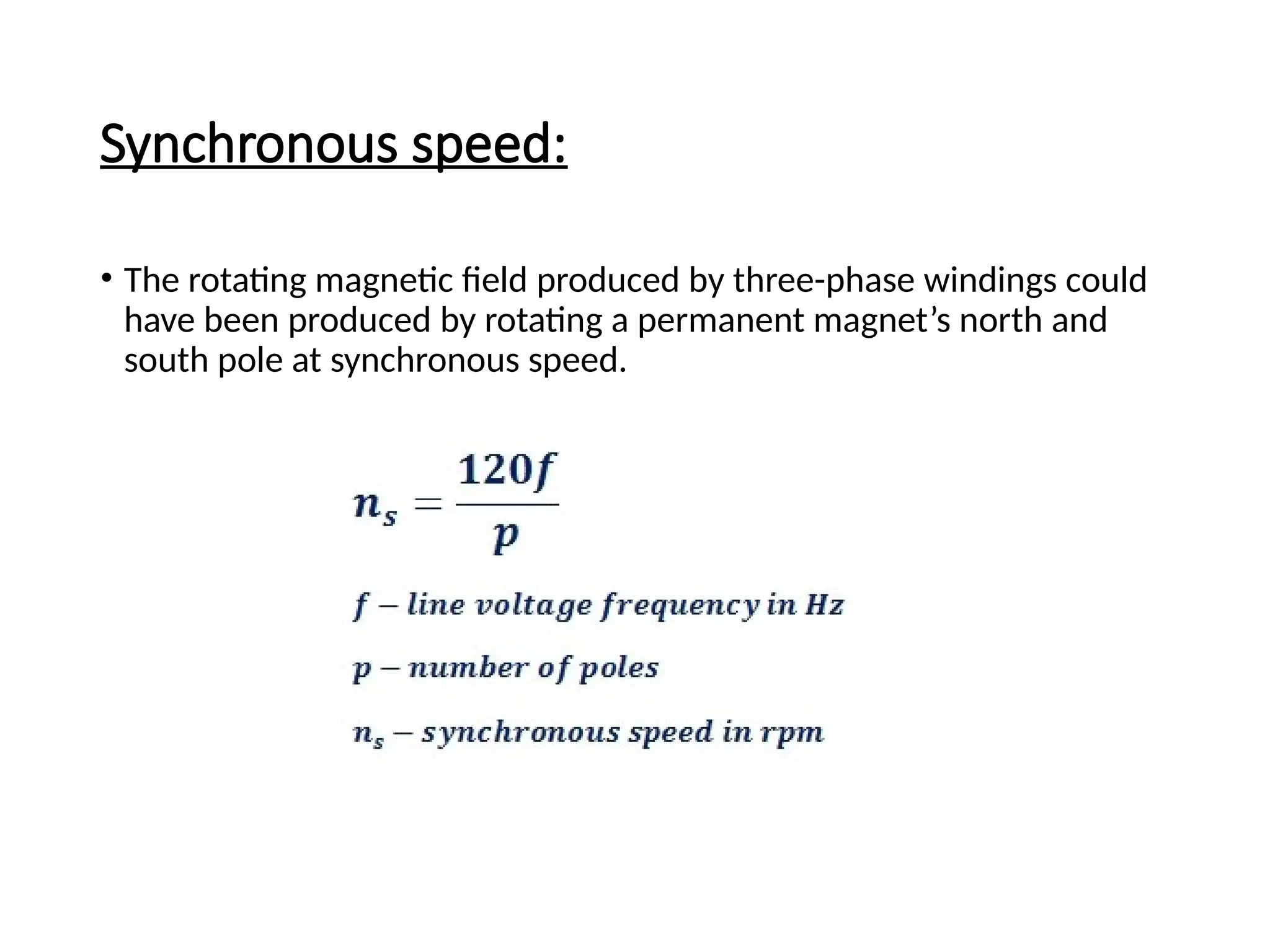
Synchronous speed:
• Therotating magnetic field produced by three-phase windings could
have been produced by rotating a permanent magnet’s north and
south pole at synchronous speed.
29.
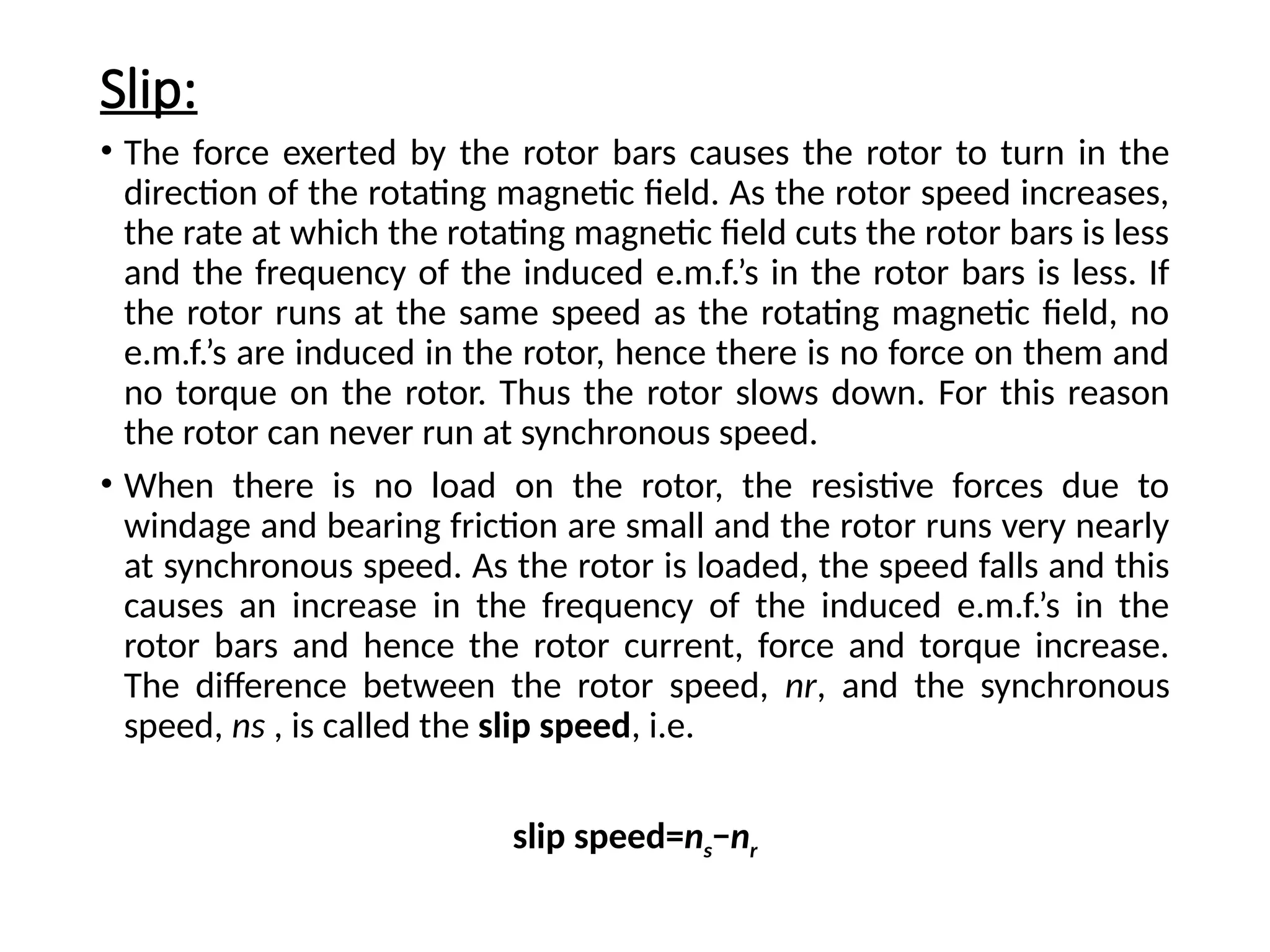
Slip:
• The forceexerted by the rotor bars causes the rotor to turn in the
direction of the rotating magnetic field. As the rotor speed increases,
the rate at which the rotating magnetic field cuts the rotor bars is less
and the frequency of the induced e.m.f.’s in the rotor bars is less. If
the rotor runs at the same speed as the rotating magnetic field, no
e.m.f.’s are induced in the rotor, hence there is no force on them and
no torque on the rotor. Thus the rotor slows down. For this reason
the rotor can never run at synchronous speed.
• When there is no load on the rotor, the resistive forces due to
windage and bearing friction are small and the rotor runs very nearly
at synchronous speed. As the rotor is loaded, the speed falls and this
causes an increase in the frequency of the induced e.m.f.’s in the
rotor bars and hence the rotor current, force and torque increase.
The difference between the rotor speed, nr, and the synchronous
speed, ns , is called the slip speed, i.e.
slip speed=ns−nr
30.
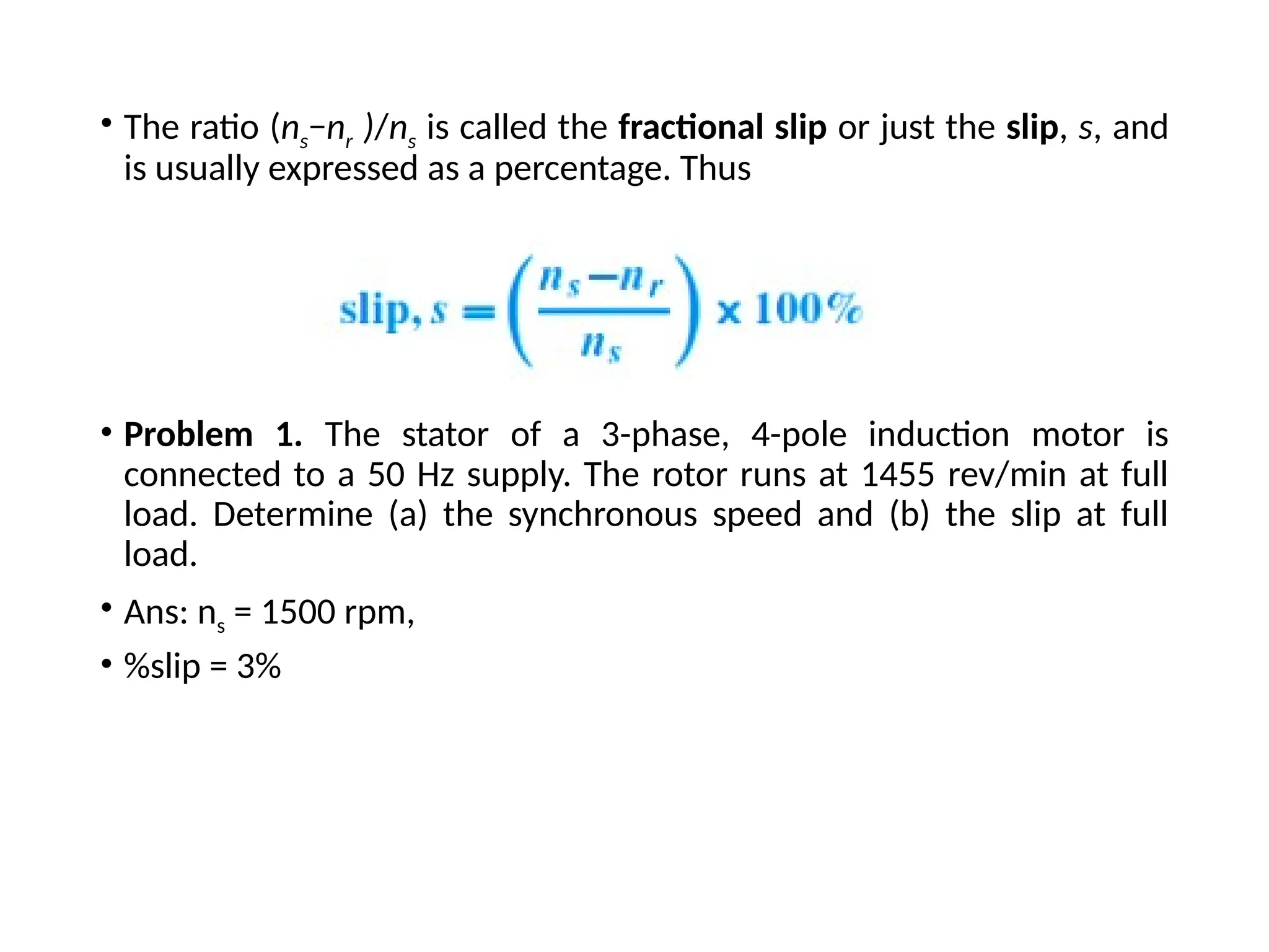
• The ratio(ns−nr )/ns is called the fractional slip or just the slip, s, and
is usually expressed as a percentage. Thus
• Problem 1. The stator of a 3-phase, 4-pole induction motor is
connected to a 50 Hz supply. The rotor runs at 1455 rev/min at full
load. Determine (a) the synchronous speed and (b) the slip at full
load.
• Ans: ns = 1500 rpm,
• %slip = 3%
31.
• Problem 1.A stator winding supplied from a three-phase 60 Hz
system is required to produce a magnetic flux rotating at 900rev/min.
Determine the number of poles.
Ans: p = 8
• Problem 2. A three-phase 2-pole motor is to have a synchronous
speed of 6000rev/min. Calculate the frequency of the supply voltage.
Ans: f = 100 Hz