Download to read offline
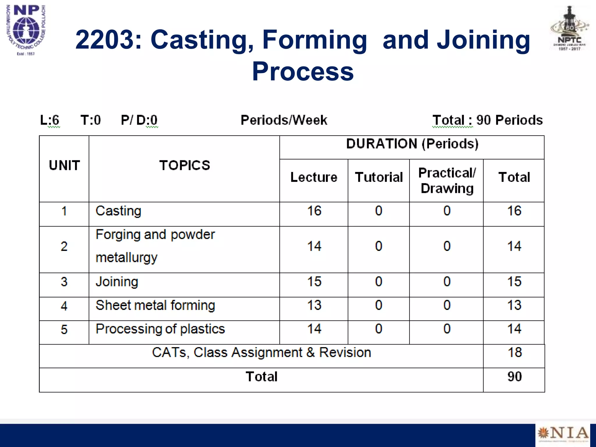
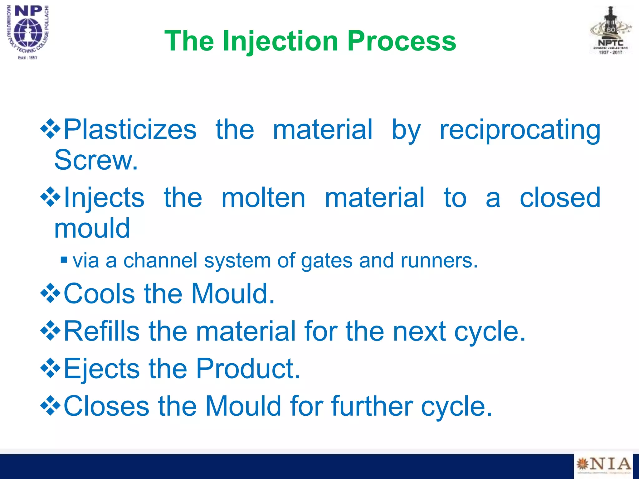
![Runner
Part
Cavity
Nozzle
Part
Cavity
Knob
Stripper
plate
Runner
Part
Cavity
Nozzle
Runner
Part
Cavity
Nozzle
Runner
Part
Cavity
Nozzle
Part
Cavity
Knob
Stripper
plate
Part
Cavity
Knob
Part
Cavity
Knob
Stripper
plate
Runner
Part
Cavity
Nozzle
Runner
Part
Cavity
Nozzle
Designing injection moulds: mould in action
[source: Lec notes, Prof T. Gutosky, MIT]](https://image.slidesharecdn.com/cfjunit5-220806040315-8a3564cf/75/CFJ-UNIT-5-ppt-44-2048.jpg)
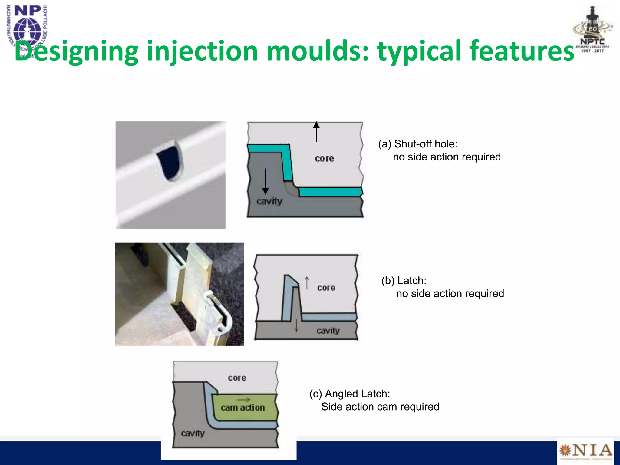
![Designing injection molds: typical features
[source: www.idsa-mp.org]](https://image.slidesharecdn.com/cfjunit5-220806040315-8a3564cf/75/CFJ-UNIT-5-ppt-45-2048.jpg)
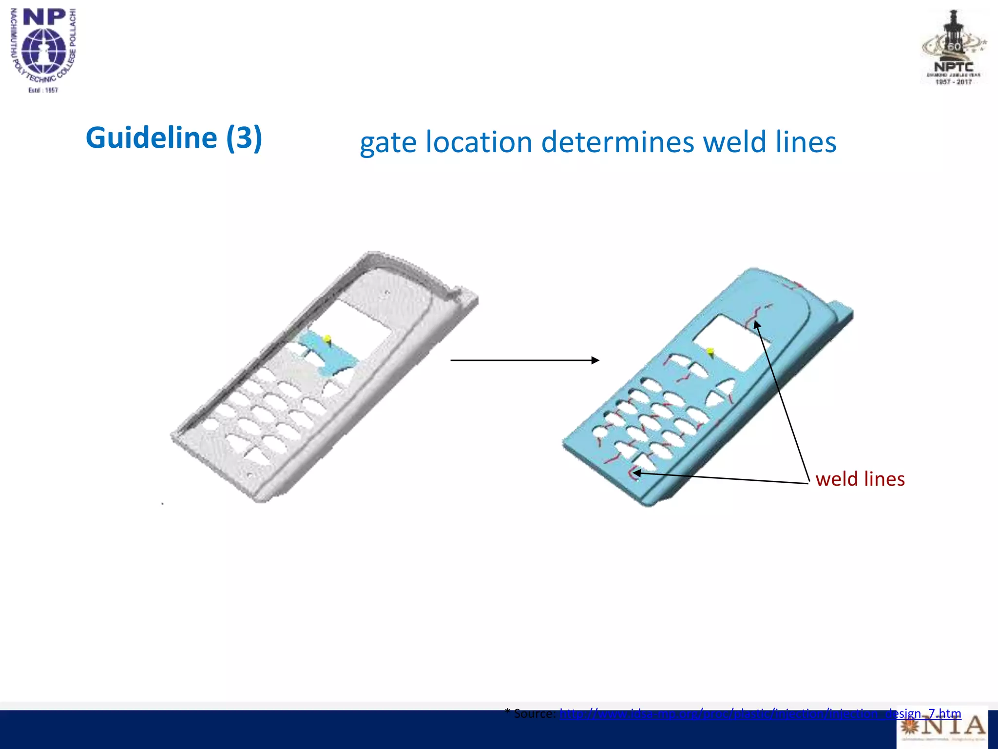
![Considerations in design of injection molded
parts
The two biggest geometric concerns
(i) proper flow of plastic to all parts of the mold cavity before solidification
(ii) shrinking of the plastic resulting in sink holes
Guideline (1) maintain uniform cross-section thickness throughout the part
How: use of ribs/gussets
[source: GE plastics: Injection Molding Design Guidelines]](https://image.slidesharecdn.com/cfjunit5-220806040315-8a3564cf/75/CFJ-UNIT-5-ppt-47-2048.jpg)
![Guideline (2) avoid thick cross-sections
[source: GE plastics: Injection Molding Design Guidelines]](https://image.slidesharecdn.com/cfjunit5-220806040315-8a3564cf/75/CFJ-UNIT-5-ppt-48-2048.jpg)

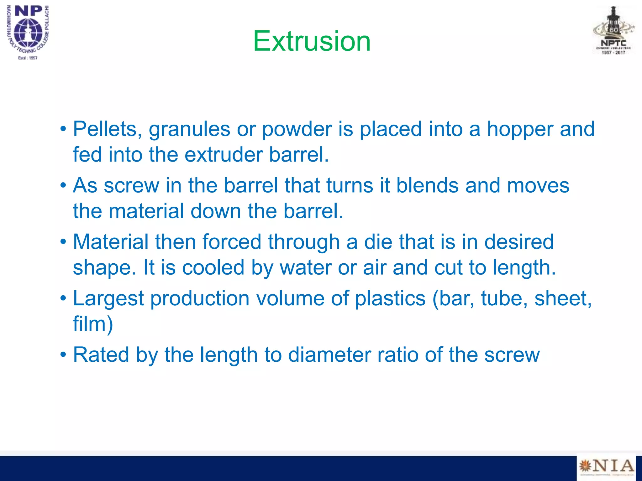
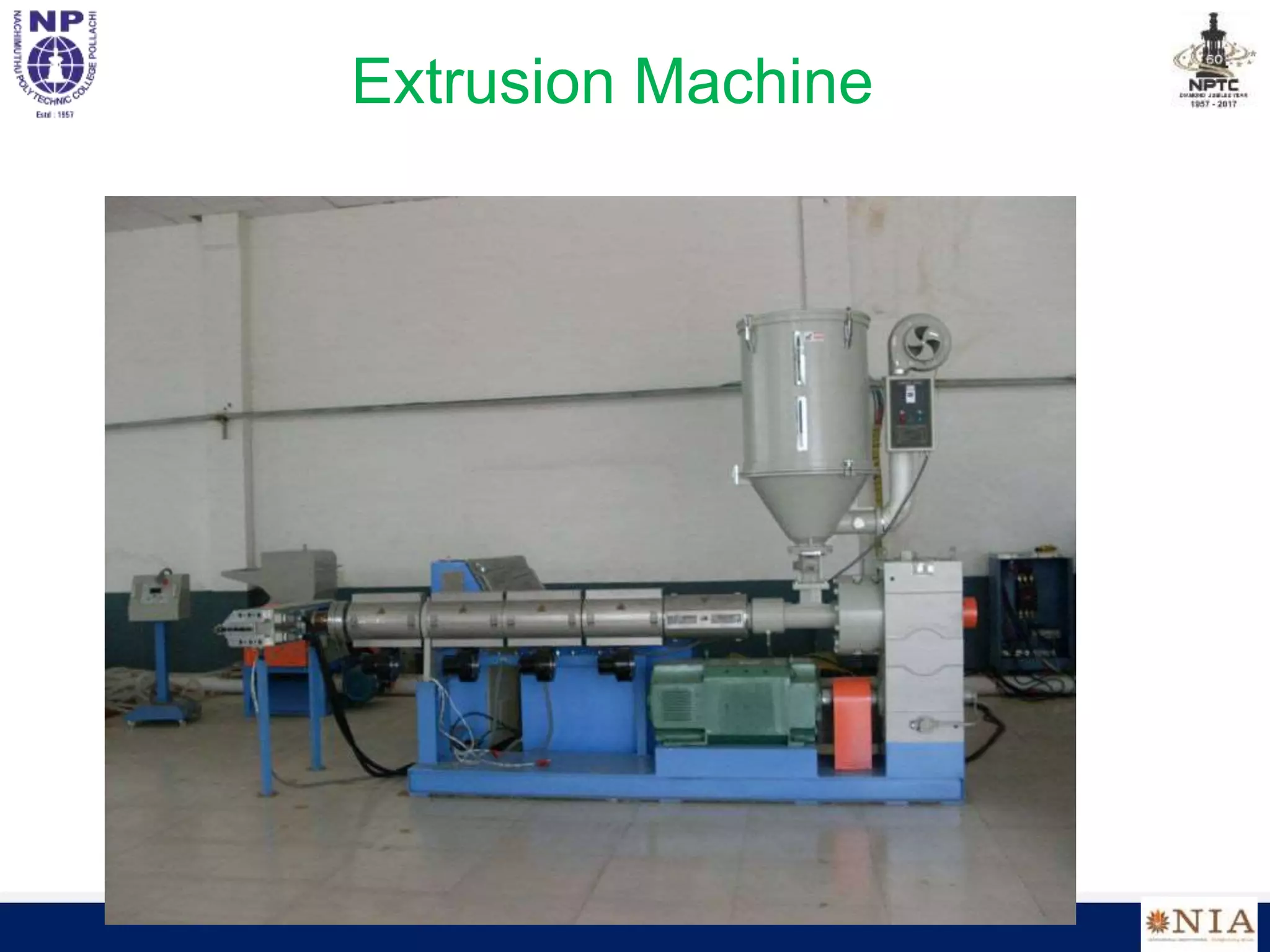
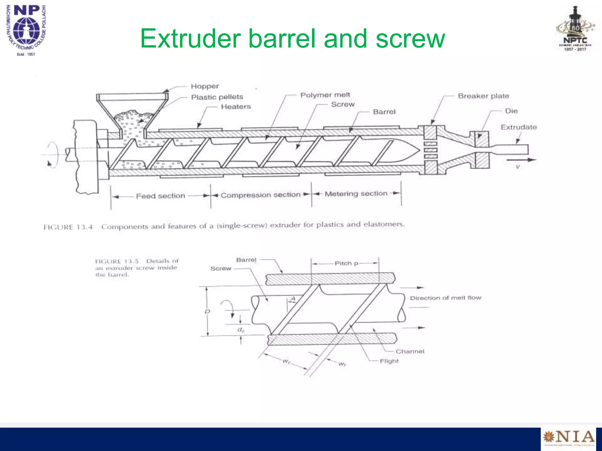
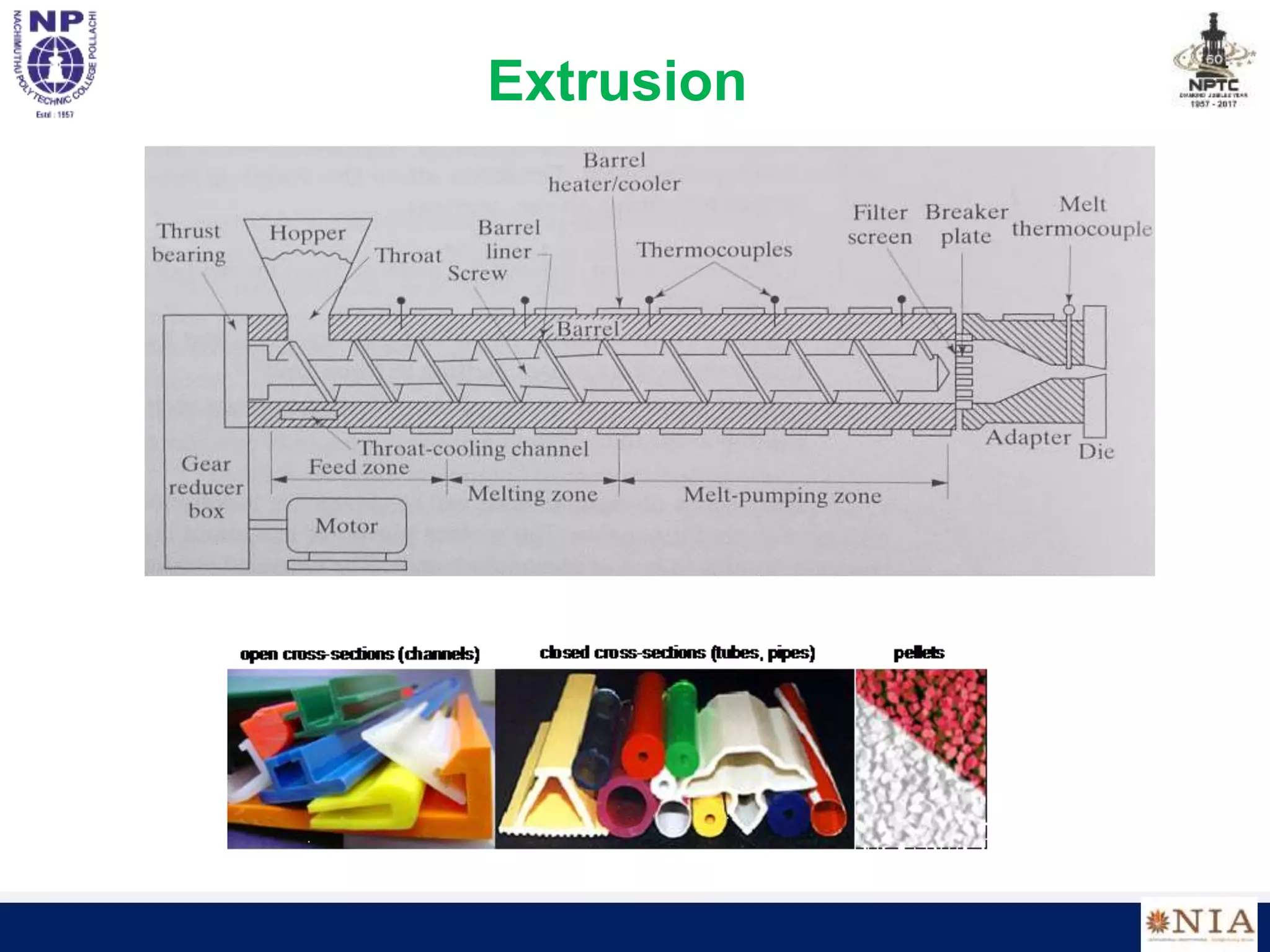
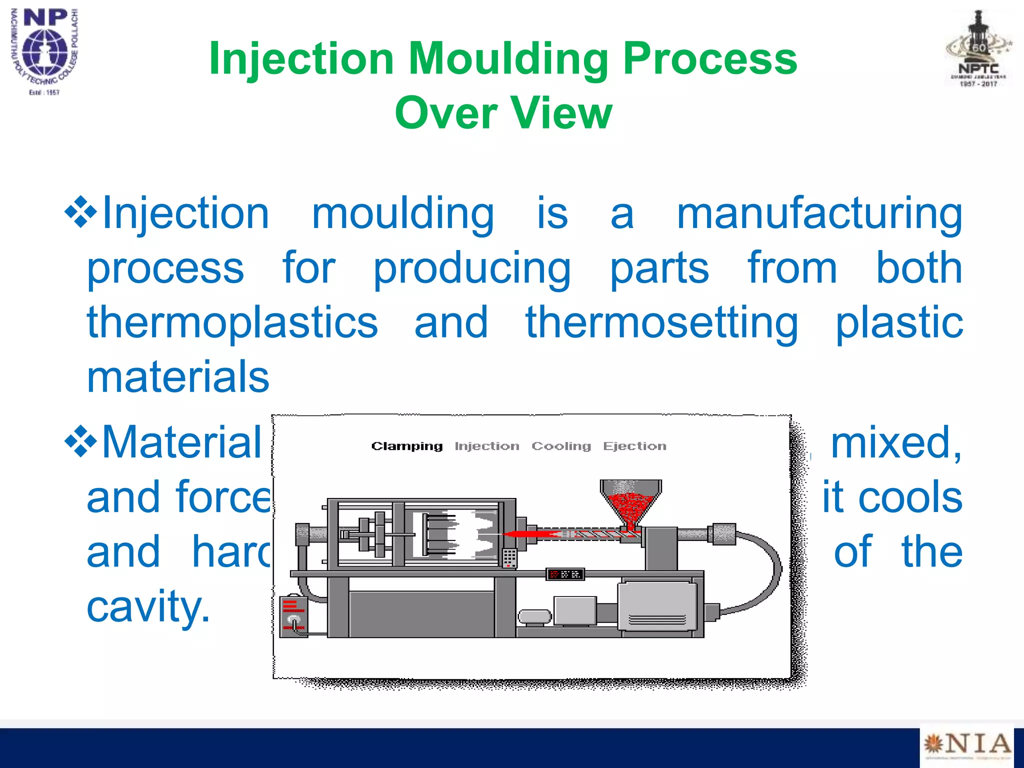
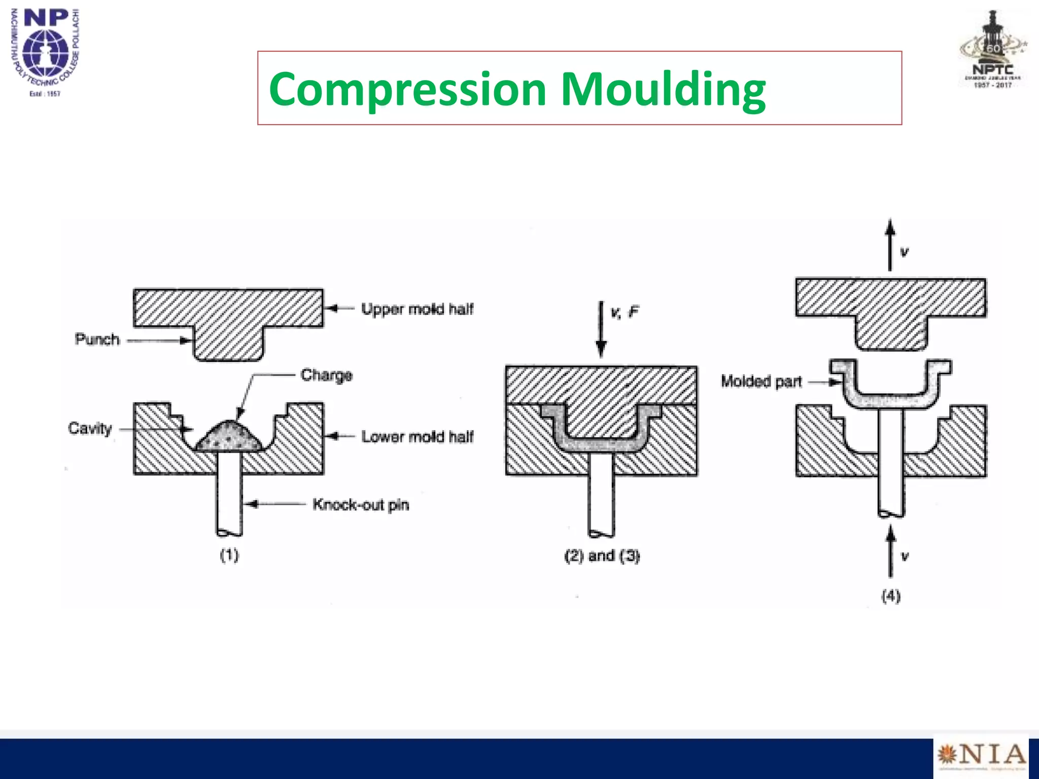
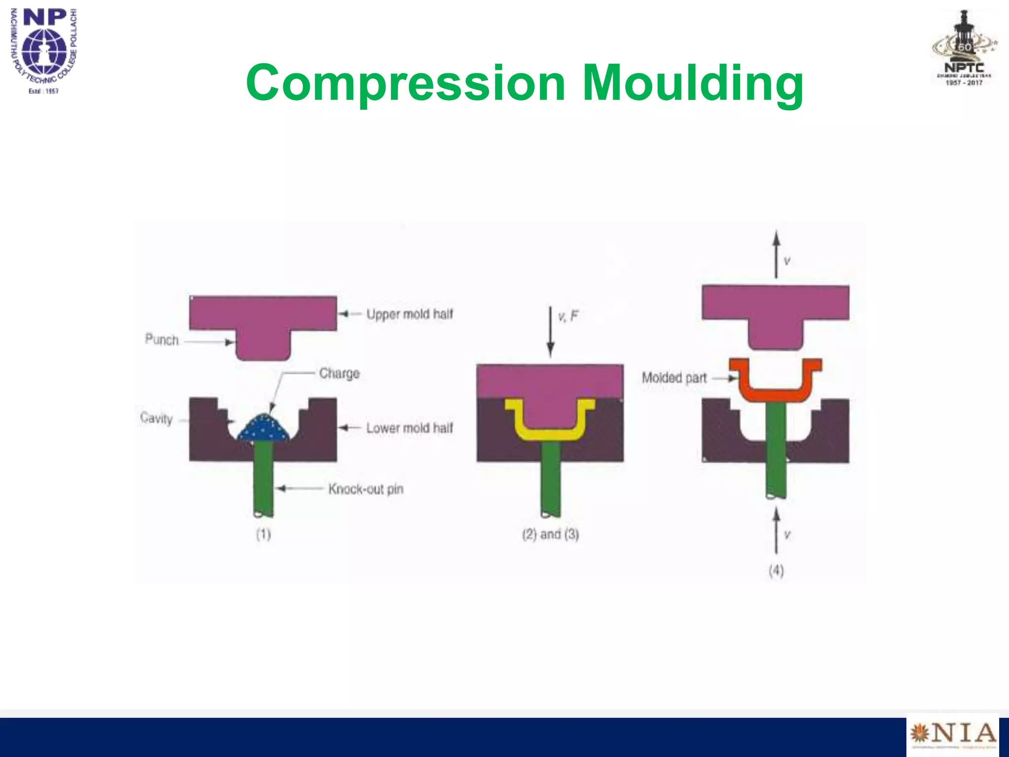
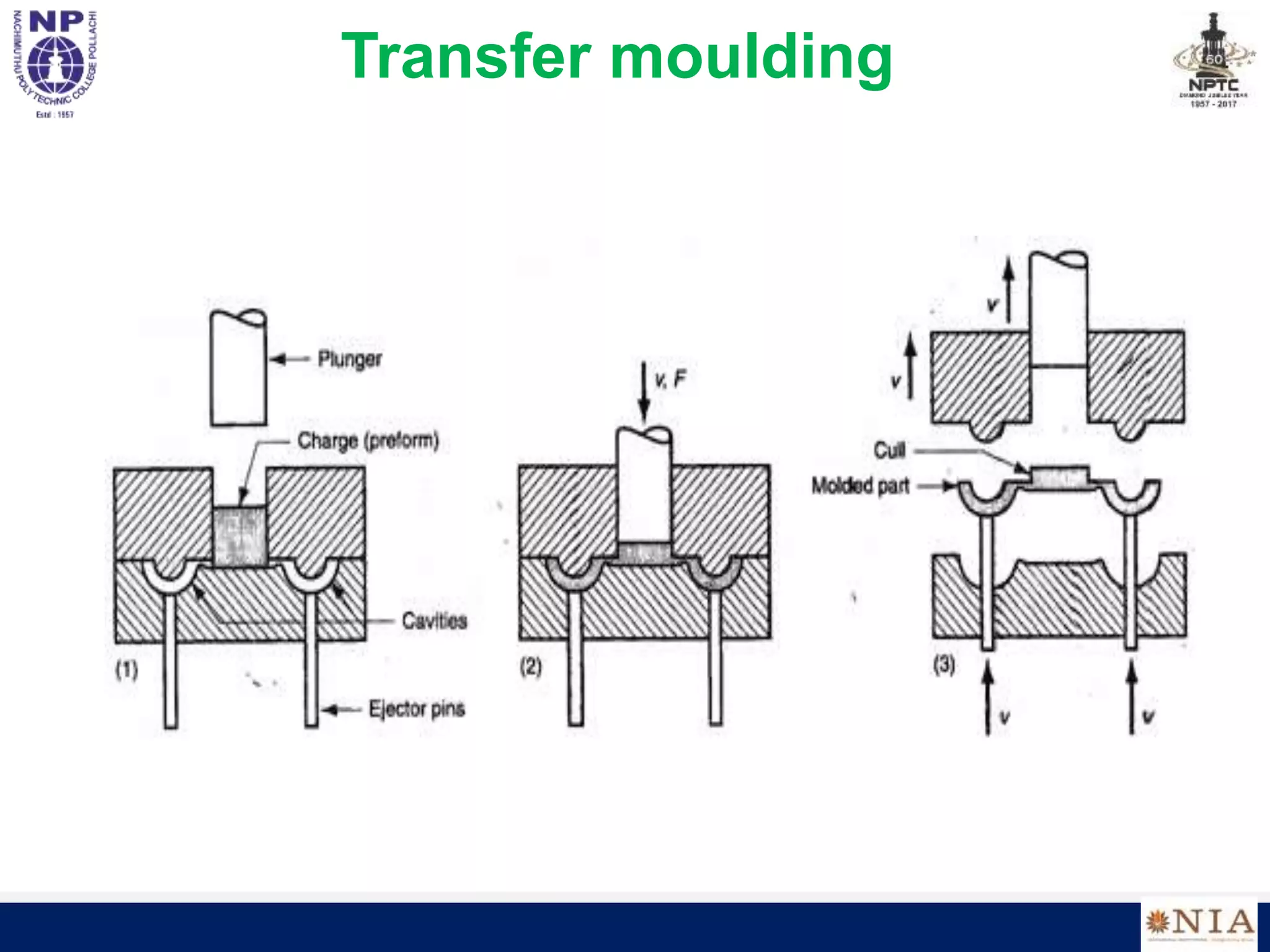
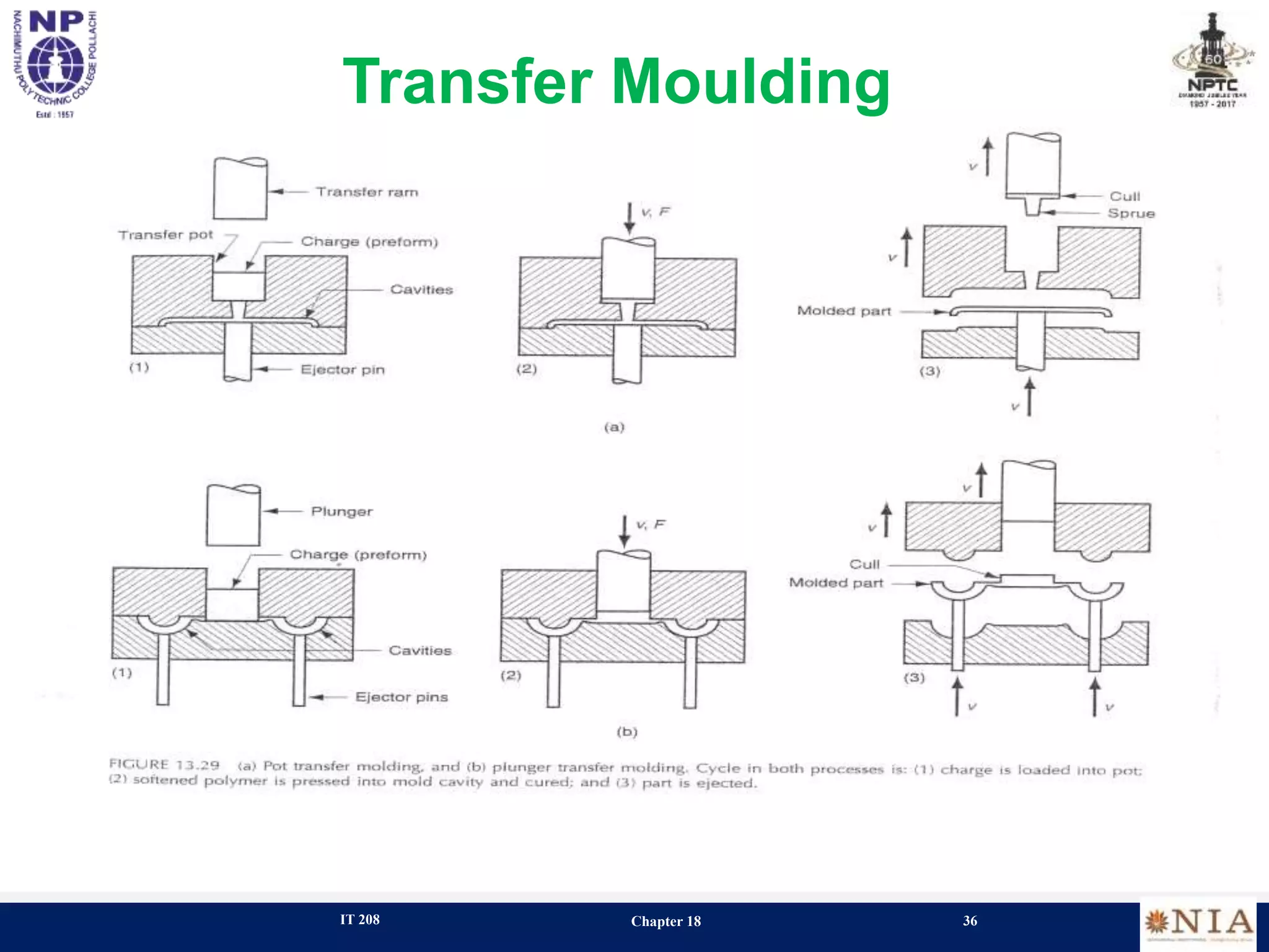
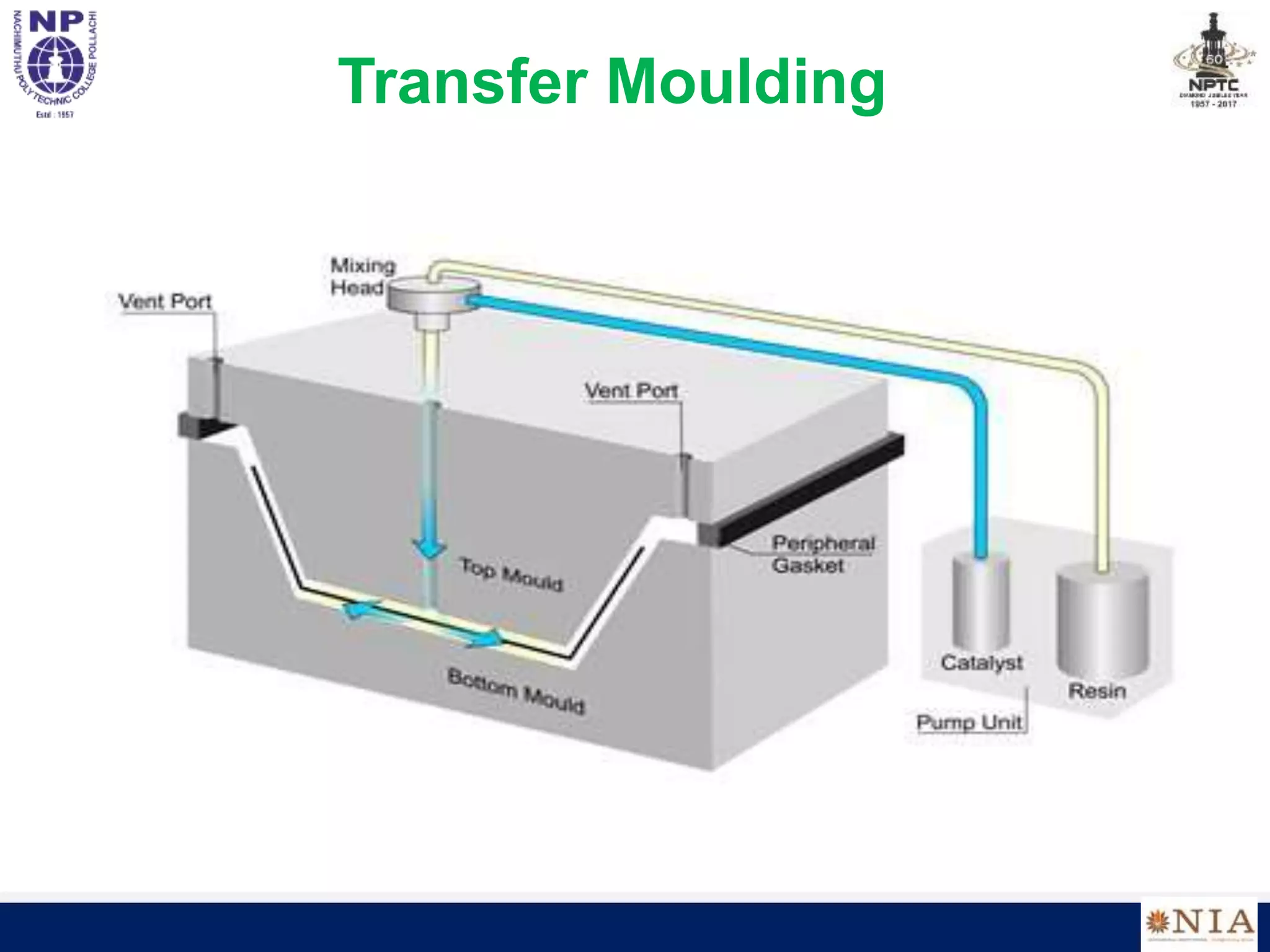
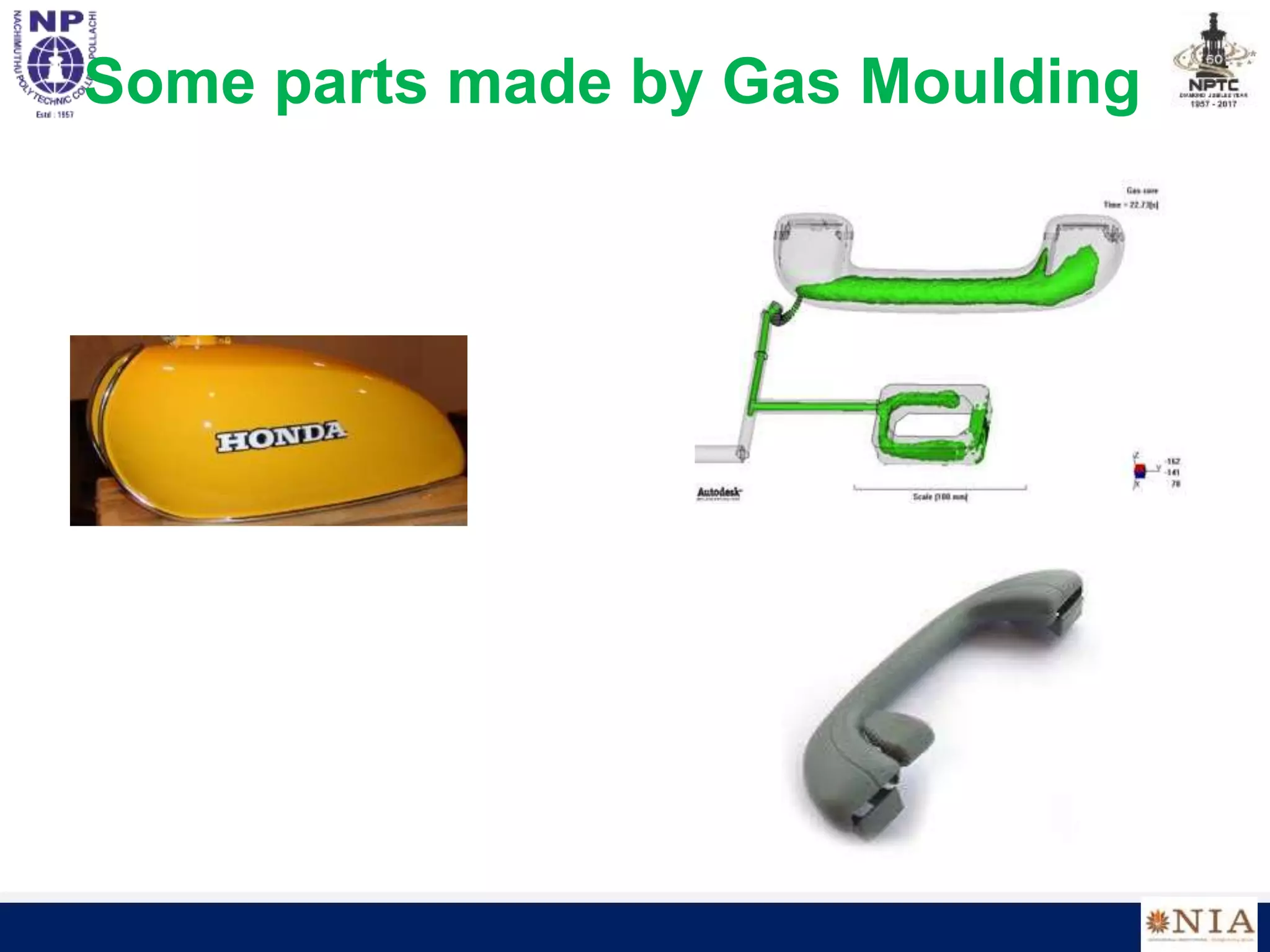
The document discusses processing of plastics and describes various plastic processing methods including injection molding, extrusion, blow molding, compression molding, transfer molding, foam injection molding, calendering, and rotational molding. It provides details of each method and examples of parts produced through each method. It also discusses considerations for designing injection molded parts such as proper flow of plastic, uniform thickness, and gate location.


