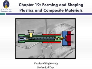
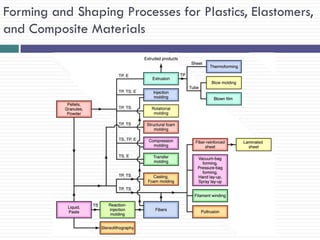
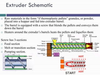
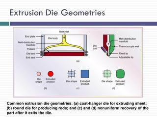
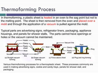
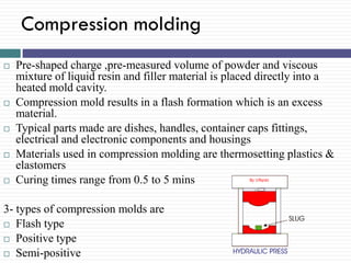
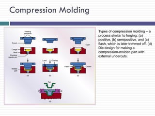
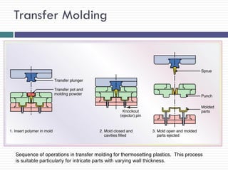
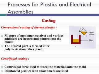
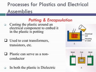
Chapter 19: Forming and Shaping
Plastics and Composite Materials

Faculty of Engineering
Mechanical Dept.
Introduction
Plastics ~ polymers
Plastics are engineered materials
 Made from natural or synthetic resins and compounds
 Low density, low tooling costs, good corrosion resistance, low cost
 Can be molded, extruded, cast, or used for coatings
 Plastics are very versatile materials and are used more than steel,
aluminum, and copper combined in the United States
 Used as food and beverage containers, packaging, signs, housewares,

foams, paints, toys, etc
 An important group: reinforced plastics (composites)
Molecular Structure of Polymers
• Hydrocarbons
CnH2n+2
Covalent bonding
Double or triple covalent
bonds may also be present
• Monomer
Smallest repeating unit

Basic structure of some polymer molecules:
(a) ethylene molecule; (b) polyethylene, a
linear chain of many ethylene molecules;
(c) molecular structure of various polymers.
These molecules are examples of the basic
building blocks for plastics
Some Plastics Terminology
Thermoplastic (TP) – Polymers that can be shaped when heated
and regain original hardness & strength upon cooling
Have a linear or branched structure (weak secondary bonds)
Process is reversible
Acrylics, cellulosics, nylons, polyethylenes, polyvinyl chloride
Thermoset (TS) – Polymers that become permanently set when
heated
Have a cross-linked structure (strong secondary bonds)
Process is irreversible
Epoxy, polyester, urethane, phenolics, silicones
Elastomer (Rubber) – Elastic; low elastic modulus
Tires, footwear, gaskets, flooring, weatherstripping, hoses
Polymer Additives
• Fillers
Improve strength, stiffness, and toughness
Reduce shrinkage and weight
Common fillers: wood flour, silica flour, clay, powdered mica
• Plasticizers
Added in small amounts to reduce viscosity
• Stabilizers and antioxidants
Retard the effects of heat, light, and oxidation
• Colorant (organic dyes or inorganic pigments)
• Flame retardants
• Lubricants
Reduce friction
Improve moldability
Facilitates part removal
Forming and Shaping Processes for Plastics, Elastomers,
and Composite Materials
Extruder Schematic






Raw materials in the form “if thermoplastic pallets” granules, or powder,
placed into a hopper and fed into extruder barrel.
The barrel is equipped with a screw that blends the pallets and conveys them
down the barrel
Heaters around the extruder’s barrels heats the pellets and liquefies them

Screw has 3-sections
 Feed section
 Melt or transition section
 Pumping section.
Extrusion Die Geometries

Common extrusion die geometries: (a) coat-hanger die for extruding sheet;
(b) round die for producing rods; and (c) and (d) nonuniform recovery of the
part after it exits the die.
Extrusion of Tubes

Extrusion of tubes. (a) Extrusion using a spider die and
pressurized air. (b) Coextrusion for producing a bottle.
Production of Plastic Film and Bags

(b)

(a) Schematic illustration of the production of thin film and plastic bags from tube
– first produced by an extruder and then blown by air. (b) A blown-film operation.
This process is well developed, producing inexpensive and very large quantities
of plastic film and shopping bags
Injection Molding












Similar to extrusion barrel is
heated
Pellets or granules fed into
heated cylinder
Melt is forced into a split-die
chamber
Molten plastic pushed into
mold cavity
Pressure ranges from 70 Mpa
– 200 Mpa

Typical products : Cups, containers,
housings, tool handles, knobs,
electrical and communication
components, toys etc.
Injection Molding Sequence
Products Made by Injection Molding

(a)

(b)

Typical products made by injection molding, including
examples of insert molding.
Mold Features for Injection Molding

Illustration of mold features for injection molding. (a) Two-plate
mold with important features identified. (b) Four parts showing
details and the volume of material involved.
Types of Molds used in Injection Molding
Injection molds have several components such as
runners, cores, cavities, cooling channels, inserts,
knock out pins and ejectors
Three basic types of molds
 Cold runner two plate mold
 Cold runner three plate mold
 Hot runner mold

Process capabilities


High production rates



Good dimensional control



Cycle time range 5 to 60 sec’s



Mold materials- tool steels, beryllium - Cu, Al



Mold life- 2 million cycles (steel molds)

10000 cycles ( Al molds)
Machines :
 Horizontal or vertical machines
 Clamping – hydraulic or electric
Injection-Molding Machine


Mixture of resin with 2 or more reactive fluids
forced into the mold cavity at high speed .



Applications : Bumpers, tenders, thermal insulation,
refrigerators and freezers, water skis, stiffness
Injection-Molding Machine

A 2.2-MN (250-ton) injection molding machine. The tonnage is the force applied to
keep the dies closed during the injection of molten plastic into the mold cavities and
hold it there until the parts are cool and stiff enough to be removed from the die.
Source: Courtesy of Cincinnati Milacron, Plastics Machinery Division.
Injection Molding: Sources of Defects
 Weld lines (similar to cold shut in metal casting)
 Unfilled die cavity if have premature solidification due to
narrow runners
 Form flash if dies do not mate properly
 Sink marks form at thick sections due to uneven cooling
causing local shrinkage

Avoid defects by:
Temperature control
Proper pressures
Simulate processes using computer software
Reaction-Injection Molding Process

In reaction-injection molding (RIM), a mixture of two or more reactive fluids is forced
under high pressure into the mold cavity. Chemical reactions take place rapidly in the
mold and the polymer solidifies, producing a thermoset part. Major applications are
automotive bumpers and fenders, thermal insulation for refrigerators and freezers, and
stiffeners for structural components. Initial injection pressures typically are much lower
than traditional injection molding.
Blow-Molding








Modified extrusion and Injection
Molding process.
A tube extruded then clamped to mold
with cavity larger than tube diameter.
Finally blown outward to fill the
cavity
Pressure 350Kpa-700Kpa

Other Blow Molding processes
 Injection Blow molding
 Multi layer Blow molding

Schematic illustrations of (a) the
extrusion blow-molding process for
making plastic beverage bottles; (b) the
injection blow-molding process; and (c)
a three-station injection molding
machine for making plastic bottles.
Rotational Molding Process
Rotational molding is used for large plastic parts.
The thin-walled metal mold is a split female mode
made of two pieces and is designed to be rotated
about two perpendicular axes.
A premeasured quantity of finely ground plastic
material is placed inside a warm mold. The mold is
then heated, usually in a large oven, while it is
rotated about the two axes.
The action tumbles the powder against the mold
where heating fuses the power without melting it.
In some cases, a cross linking agent is added to
the powder, and cross linking occurs after the part
is formed in the mold by continued heating.
Typical parts are tanks, trash cans, boat hulls, buckets, housings, toys, carrying
cases, and footballs. Various metallic or plastic inserts may also be molded into the
parts.
Slush-molding


Plastisols are used in slush molding



Plastic materials are forced against the inside walls of
the heated mold by tumbling action.



The part is cooled while it is still rotating and then
removed by opening the mold
Thermoforming Process
In thermoforming, a plastic sheet is heated in an oven to the sag point but not to
the melting point. The sheet is then removed from the oven and placed over a
mold and through the application of a vacuum is pulled against the mold.
Typical parts are advertising signs, refrigerator liners, packaging, appliance
housings, and panels for shower stalls. The parts cannot have openings or
holes or the vacuum cannot be maintained.

Various thermoforming processes for a thermoplastic sheet. These processes commonly are
used in making advertising signs, cookie and candy trays, panels for shower stall, and
packaging.
Compression molding










Pre-shaped charge ,pre-measured volume of powder and viscous
mixture of liquid resin and filler material is placed directly into a
heated mold cavity.
Compression mold results in a flash formation which is an excess
material.
Typical parts made are dishes, handles, container caps fittings,
electrical and electronic components and housings
Materials used in compression molding are thermosetting plastics &
elastomers
Curing times range from 0.5 to 5 mins

3- types of compression molds are
 Flash type
 Positive type
 Semi-positive
Compression Molding
Types of compression molding – a
process similar to forging: (a)
positive, (b) semipositive, and (c)
flash, which is later trimmed off. (d)
Die design for making a
compression-molded part with
external undercuts.
Transfer Molding








Transfer molding is an improvement if compression
molding
Uncured thermosetting material placed in a heated transfer
pot or chamber, which is injected into heated closed molds
Ram plunger or rotating screw feeder forces material into
mold cavity through narrow channels
This flow generates heat and resin is molten as it enters the
mold

Typical parts : Electrical & electronic components, rubber and
silicone parts
Transfer Molding

Sequence of operations in transfer molding for thermosetting plastics. This process
is suitable particularly for intricate parts with varying wall thickness.
Processes for Plastics and Electrical
Assemblies
Casting
Conventional casting of thermo plastics :




Mixture of monomer, catalyst and various
additives are heated and poured into the
mould
The desired part is formed after
polymerization takes place.

Centrifugal casting :



Centrifugal force used to stack the material onto the mold
Reinforced plastics with short fibers are used
Processes for Plastics and Electrical
Assemblies
Potting & Encapsulation


Casting the plastic around an
electrical component to embed it
in the plastic is potting

 Used to coat transformers,
transistors, etc.
 Plastic can serve as a nonconductor


In both the plastic is Dielectric
Foam Molding


Polystyrene beads are placed in a mold and heated



Beads will expand up to 50 times their original size



Changing the bead size will determine the density of
the finished foam part



Used to make styrofoam cups, insulating blocks and
packaging materials
Foam Molding
Cold forming


Processes such as rolling ,deep drawing extrusion closed
die forging ,coining and rubber forming can be used for
thermoplastics at room temperatures



Typical materials used : Poly propylene, poly carbonate,
Abs, and rigid PVC

Considerations :
 Sufficiently ductile material at room temperature
 Non recoverable material deformation
Calendaring
Schematic illustration
of calendering.
Sheets produced by
this process
subsequently are
used in
thermoforming. The
process also is used
in the production of
various elastomer
and rubber products.

In calendering, sheets of plastic are laminated together by rolling through
heated roller. Basically, warm or molten plastic (usually from an extruder)
is fed through a series of heated rolls as in this figure. The gaps between
the rolls determine the final sheet size. Each additional roll would reduce
the sheet thickness further. Then, once the laminated sheet is the correct
thickness, the sheet is then stripped off.
Processing Polymer-Matrix Composites





PMCs have high
strength/stiffness to weight
ratio and excellent creep
resistance.
They consist of the polymer
and reinforcing fibers,
bonded together in various
ways.

Reinforced-plastic components for a
Honda motorcycle. The parts shown are
front and rear forks, a rear swing arm, a
wheel, and brake disks.
Polymer-Matrix Composites: Fiber Impregnation




Fibers can consist of fiberglass, graphite, boron, ceramic
and kevlar.
Prepregs are made by dipping continuous fibers in resin.

(a) Manufacturing process for polymer-matrix composite tape. (b) Boron-epoxy prepreg
tape. These tapes are then used in making reinforced plastic parts and components with
high strength-to-weight ratios, particularly important for aircraft and aerospace applications
and sports equipment.
Polymer-Matrix Composites: Fiber Impregnation


Sheet-molding compounds are made by dropping randomly
oriented pieces of fiber on a layer of resin paste, under
which there is a thin sheet of polymer (carrier film).

Schematic illustration of the
manufacturing process for
producing fiber-reinforced
plastic sheets. The sheet
still is viscous at this stage
and later can be shped into
various products.
Polymer-Matrix Composites: Examples
Polymer-Matrix Composites: Filament Winding





Fibers are dipped in resin bath
They are then wrapped around an object by means
of rotating mandrel
Used to strengthen pressure vessels.
Polymer-Matrix Composites: Pultrusion




Fibers are run continuously through a resin bath before
being pulled through a set of dies.
Used to make golf clubs, ski poles, ladders.

(a) Schematic illustration of the pultrusion process. (b) Examples of parts made by pultrusion.
The major components of fiberglass ladders (used especially by electricians) are made by this
process. Unlike aluminum ladders, they are available in different colors but are heavier because of
the presence of glass fibers. Source: Courtesy of Strongwell Corporation.
Processing Metal-Matrix and Ceramic-Matrix
Composites
Liquid Phase Processing





Liquid metal-matrix and solid reinforcement are either cast or
pressure-infiltration cast
Metal-matrix is usually aluminum or titanium
Solid reinforcement is usually graphite, aluminum oxide or
silicon carbide.

Solid Phase Processing



Powder-metallurgy techniques are used
Example: tungsten-carbide reinforced tools.
Design Considerations: Plastics and Composites








Compared to metals, plastics have lower stiffness and
strength.
Dimensional tolerances, except with injection
molding, are higher than with metals
For casting, ensuring proper flow into mold cavities
is important
Variations in section thicknesses or abrupt changes in
geometry should be avoided.
Design Modifications to Minimize Distortion in Plastic Parts

Examples of design modifications to eliminate or minimize distortion in plastic parts: (a)
suggested design changes to minimize distortion; (b) stiffening the bottoms of thin plastic
containers by doming – a technique similar to the process used to shape the bottoms of
aluminum beverage cans; and (c) design change in a rib to minimize pull-in (sink mark)
caused by shrinkage during the cooling of thick sections in molded parts.
Chapter19

Chapter19

  • 1.
    Chapter 19: Formingand Shaping Plastics and Composite Materials Faculty of Engineering Mechanical Dept.
  • 2.
    Introduction Plastics ~ polymers Plasticsare engineered materials  Made from natural or synthetic resins and compounds  Low density, low tooling costs, good corrosion resistance, low cost  Can be molded, extruded, cast, or used for coatings  Plastics are very versatile materials and are used more than steel, aluminum, and copper combined in the United States  Used as food and beverage containers, packaging, signs, housewares, foams, paints, toys, etc  An important group: reinforced plastics (composites)
  • 3.
    Molecular Structure ofPolymers • Hydrocarbons CnH2n+2 Covalent bonding Double or triple covalent bonds may also be present • Monomer Smallest repeating unit Basic structure of some polymer molecules: (a) ethylene molecule; (b) polyethylene, a linear chain of many ethylene molecules; (c) molecular structure of various polymers. These molecules are examples of the basic building blocks for plastics
  • 4.
    Some Plastics Terminology Thermoplastic(TP) – Polymers that can be shaped when heated and regain original hardness & strength upon cooling Have a linear or branched structure (weak secondary bonds) Process is reversible Acrylics, cellulosics, nylons, polyethylenes, polyvinyl chloride Thermoset (TS) – Polymers that become permanently set when heated Have a cross-linked structure (strong secondary bonds) Process is irreversible Epoxy, polyester, urethane, phenolics, silicones Elastomer (Rubber) – Elastic; low elastic modulus Tires, footwear, gaskets, flooring, weatherstripping, hoses
  • 5.
    Polymer Additives • Fillers Improvestrength, stiffness, and toughness Reduce shrinkage and weight Common fillers: wood flour, silica flour, clay, powdered mica • Plasticizers Added in small amounts to reduce viscosity • Stabilizers and antioxidants Retard the effects of heat, light, and oxidation • Colorant (organic dyes or inorganic pigments) • Flame retardants • Lubricants Reduce friction Improve moldability Facilitates part removal
  • 6.
    Forming and ShapingProcesses for Plastics, Elastomers, and Composite Materials
  • 7.
    Extruder Schematic    Raw materialsin the form “if thermoplastic pallets” granules, or powder, placed into a hopper and fed into extruder barrel. The barrel is equipped with a screw that blends the pallets and conveys them down the barrel Heaters around the extruder’s barrels heats the pellets and liquefies them Screw has 3-sections  Feed section  Melt or transition section  Pumping section.
  • 8.
    Extrusion Die Geometries Commonextrusion die geometries: (a) coat-hanger die for extruding sheet; (b) round die for producing rods; and (c) and (d) nonuniform recovery of the part after it exits the die.
  • 9.
    Extrusion of Tubes Extrusionof tubes. (a) Extrusion using a spider die and pressurized air. (b) Coextrusion for producing a bottle.
  • 10.
    Production of PlasticFilm and Bags (b) (a) Schematic illustration of the production of thin film and plastic bags from tube – first produced by an extruder and then blown by air. (b) A blown-film operation. This process is well developed, producing inexpensive and very large quantities of plastic film and shopping bags
  • 12.
    Injection Molding       Similar toextrusion barrel is heated Pellets or granules fed into heated cylinder Melt is forced into a split-die chamber Molten plastic pushed into mold cavity Pressure ranges from 70 Mpa – 200 Mpa Typical products : Cups, containers, housings, tool handles, knobs, electrical and communication components, toys etc.
  • 13.
  • 14.
    Products Made byInjection Molding (a) (b) Typical products made by injection molding, including examples of insert molding.
  • 15.
    Mold Features forInjection Molding Illustration of mold features for injection molding. (a) Two-plate mold with important features identified. (b) Four parts showing details and the volume of material involved.
  • 16.
    Types of Moldsused in Injection Molding Injection molds have several components such as runners, cores, cavities, cooling channels, inserts, knock out pins and ejectors Three basic types of molds  Cold runner two plate mold  Cold runner three plate mold  Hot runner mold 
  • 18.
    Process capabilities  High productionrates  Good dimensional control  Cycle time range 5 to 60 sec’s  Mold materials- tool steels, beryllium - Cu, Al  Mold life- 2 million cycles (steel molds) 10000 cycles ( Al molds) Machines :  Horizontal or vertical machines  Clamping – hydraulic or electric
  • 19.
    Injection-Molding Machine  Mixture ofresin with 2 or more reactive fluids forced into the mold cavity at high speed .  Applications : Bumpers, tenders, thermal insulation, refrigerators and freezers, water skis, stiffness
  • 20.
    Injection-Molding Machine A 2.2-MN(250-ton) injection molding machine. The tonnage is the force applied to keep the dies closed during the injection of molten plastic into the mold cavities and hold it there until the parts are cool and stiff enough to be removed from the die. Source: Courtesy of Cincinnati Milacron, Plastics Machinery Division.
  • 21.
    Injection Molding: Sourcesof Defects  Weld lines (similar to cold shut in metal casting)  Unfilled die cavity if have premature solidification due to narrow runners  Form flash if dies do not mate properly  Sink marks form at thick sections due to uneven cooling causing local shrinkage Avoid defects by: Temperature control Proper pressures Simulate processes using computer software
  • 22.
    Reaction-Injection Molding Process Inreaction-injection molding (RIM), a mixture of two or more reactive fluids is forced under high pressure into the mold cavity. Chemical reactions take place rapidly in the mold and the polymer solidifies, producing a thermoset part. Major applications are automotive bumpers and fenders, thermal insulation for refrigerators and freezers, and stiffeners for structural components. Initial injection pressures typically are much lower than traditional injection molding.
  • 23.
    Blow-Molding     Modified extrusion andInjection Molding process. A tube extruded then clamped to mold with cavity larger than tube diameter. Finally blown outward to fill the cavity Pressure 350Kpa-700Kpa Other Blow Molding processes  Injection Blow molding  Multi layer Blow molding Schematic illustrations of (a) the extrusion blow-molding process for making plastic beverage bottles; (b) the injection blow-molding process; and (c) a three-station injection molding machine for making plastic bottles.
  • 25.
    Rotational Molding Process Rotationalmolding is used for large plastic parts. The thin-walled metal mold is a split female mode made of two pieces and is designed to be rotated about two perpendicular axes. A premeasured quantity of finely ground plastic material is placed inside a warm mold. The mold is then heated, usually in a large oven, while it is rotated about the two axes. The action tumbles the powder against the mold where heating fuses the power without melting it. In some cases, a cross linking agent is added to the powder, and cross linking occurs after the part is formed in the mold by continued heating. Typical parts are tanks, trash cans, boat hulls, buckets, housings, toys, carrying cases, and footballs. Various metallic or plastic inserts may also be molded into the parts.
  • 26.
    Slush-molding  Plastisols are usedin slush molding  Plastic materials are forced against the inside walls of the heated mold by tumbling action.  The part is cooled while it is still rotating and then removed by opening the mold
  • 27.
    Thermoforming Process In thermoforming,a plastic sheet is heated in an oven to the sag point but not to the melting point. The sheet is then removed from the oven and placed over a mold and through the application of a vacuum is pulled against the mold. Typical parts are advertising signs, refrigerator liners, packaging, appliance housings, and panels for shower stalls. The parts cannot have openings or holes or the vacuum cannot be maintained. Various thermoforming processes for a thermoplastic sheet. These processes commonly are used in making advertising signs, cookie and candy trays, panels for shower stall, and packaging.
  • 28.
    Compression molding      Pre-shaped charge,pre-measured volume of powder and viscous mixture of liquid resin and filler material is placed directly into a heated mold cavity. Compression mold results in a flash formation which is an excess material. Typical parts made are dishes, handles, container caps fittings, electrical and electronic components and housings Materials used in compression molding are thermosetting plastics & elastomers Curing times range from 0.5 to 5 mins 3- types of compression molds are  Flash type  Positive type  Semi-positive
  • 29.
    Compression Molding Types ofcompression molding – a process similar to forging: (a) positive, (b) semipositive, and (c) flash, which is later trimmed off. (d) Die design for making a compression-molded part with external undercuts.
  • 30.
    Transfer Molding     Transfer moldingis an improvement if compression molding Uncured thermosetting material placed in a heated transfer pot or chamber, which is injected into heated closed molds Ram plunger or rotating screw feeder forces material into mold cavity through narrow channels This flow generates heat and resin is molten as it enters the mold Typical parts : Electrical & electronic components, rubber and silicone parts
  • 31.
    Transfer Molding Sequence ofoperations in transfer molding for thermosetting plastics. This process is suitable particularly for intricate parts with varying wall thickness.
  • 32.
    Processes for Plasticsand Electrical Assemblies Casting Conventional casting of thermo plastics :   Mixture of monomer, catalyst and various additives are heated and poured into the mould The desired part is formed after polymerization takes place. Centrifugal casting :   Centrifugal force used to stack the material onto the mold Reinforced plastics with short fibers are used
  • 33.
    Processes for Plasticsand Electrical Assemblies Potting & Encapsulation  Casting the plastic around an electrical component to embed it in the plastic is potting  Used to coat transformers, transistors, etc.  Plastic can serve as a nonconductor  In both the plastic is Dielectric
  • 34.
    Foam Molding  Polystyrene beadsare placed in a mold and heated  Beads will expand up to 50 times their original size  Changing the bead size will determine the density of the finished foam part  Used to make styrofoam cups, insulating blocks and packaging materials
  • 35.
  • 36.
    Cold forming  Processes suchas rolling ,deep drawing extrusion closed die forging ,coining and rubber forming can be used for thermoplastics at room temperatures  Typical materials used : Poly propylene, poly carbonate, Abs, and rigid PVC Considerations :  Sufficiently ductile material at room temperature  Non recoverable material deformation
  • 37.
    Calendaring Schematic illustration of calendering. Sheetsproduced by this process subsequently are used in thermoforming. The process also is used in the production of various elastomer and rubber products. In calendering, sheets of plastic are laminated together by rolling through heated roller. Basically, warm or molten plastic (usually from an extruder) is fed through a series of heated rolls as in this figure. The gaps between the rolls determine the final sheet size. Each additional roll would reduce the sheet thickness further. Then, once the laminated sheet is the correct thickness, the sheet is then stripped off.
  • 38.
    Processing Polymer-Matrix Composites   PMCshave high strength/stiffness to weight ratio and excellent creep resistance. They consist of the polymer and reinforcing fibers, bonded together in various ways. Reinforced-plastic components for a Honda motorcycle. The parts shown are front and rear forks, a rear swing arm, a wheel, and brake disks.
  • 39.
    Polymer-Matrix Composites: FiberImpregnation   Fibers can consist of fiberglass, graphite, boron, ceramic and kevlar. Prepregs are made by dipping continuous fibers in resin. (a) Manufacturing process for polymer-matrix composite tape. (b) Boron-epoxy prepreg tape. These tapes are then used in making reinforced plastic parts and components with high strength-to-weight ratios, particularly important for aircraft and aerospace applications and sports equipment.
  • 40.
    Polymer-Matrix Composites: FiberImpregnation  Sheet-molding compounds are made by dropping randomly oriented pieces of fiber on a layer of resin paste, under which there is a thin sheet of polymer (carrier film). Schematic illustration of the manufacturing process for producing fiber-reinforced plastic sheets. The sheet still is viscous at this stage and later can be shped into various products.
  • 41.
  • 42.
    Polymer-Matrix Composites: FilamentWinding    Fibers are dipped in resin bath They are then wrapped around an object by means of rotating mandrel Used to strengthen pressure vessels.
  • 43.
    Polymer-Matrix Composites: Pultrusion   Fibersare run continuously through a resin bath before being pulled through a set of dies. Used to make golf clubs, ski poles, ladders. (a) Schematic illustration of the pultrusion process. (b) Examples of parts made by pultrusion. The major components of fiberglass ladders (used especially by electricians) are made by this process. Unlike aluminum ladders, they are available in different colors but are heavier because of the presence of glass fibers. Source: Courtesy of Strongwell Corporation.
  • 44.
    Processing Metal-Matrix andCeramic-Matrix Composites Liquid Phase Processing    Liquid metal-matrix and solid reinforcement are either cast or pressure-infiltration cast Metal-matrix is usually aluminum or titanium Solid reinforcement is usually graphite, aluminum oxide or silicon carbide. Solid Phase Processing   Powder-metallurgy techniques are used Example: tungsten-carbide reinforced tools.
  • 45.
    Design Considerations: Plasticsand Composites     Compared to metals, plastics have lower stiffness and strength. Dimensional tolerances, except with injection molding, are higher than with metals For casting, ensuring proper flow into mold cavities is important Variations in section thicknesses or abrupt changes in geometry should be avoided.
  • 46.
    Design Modifications toMinimize Distortion in Plastic Parts Examples of design modifications to eliminate or minimize distortion in plastic parts: (a) suggested design changes to minimize distortion; (b) stiffening the bottoms of thin plastic containers by doming – a technique similar to the process used to shape the bottoms of aluminum beverage cans; and (c) design change in a rib to minimize pull-in (sink mark) caused by shrinkage during the cooling of thick sections in molded parts.