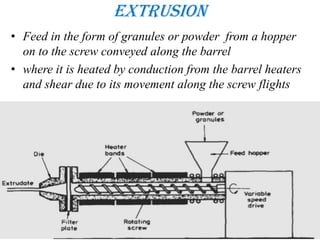
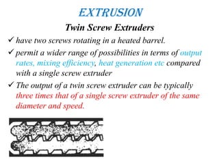
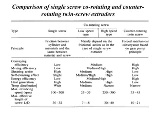
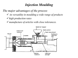
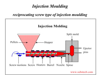
3. Introduction to plastic
engineering
• It would be difficult to imagine our modern world
without plastics
• Its integral part of everyone’s lifestyle with
applications varying from common place domestic
articles to sophisticated scientific and medical
instruments.
• Plastics offer advantages such as lightness,
resilience, resistance to corrosion, colour fastness,
transparency, ease of processing, etc.,
4. Introduction to plastic
engineering
• although they have their limitations, their exploitation is
limited only by the ingenuity of the designer
• Few designers would simply specify metal as the material for
a particular component so it would be equally unsatisfactory
just to recommend plastic.
• This analogy can be taken still further because in the same
way that there are different grades of steel there are also
different grades of, say, polypropylene.
• In both cases the good designer will recognize this and select
the most appropriate material and grade on the basis of
process ability, toughness, chemical resistance, etc
5.
6. Introduction to plastic
engineering
• The words polymers and plastics are often taken as
synonymous but in fact there is a distinction.
• polymer is the pure material which results from the process of
polymerisation and is usually taken as the family name for
materials which have long chain-like molecules.
• when additives are present that the term plastic is applied
• Polymers contain additives for a number of reasons…...
• Antistatic Agents: Most polymers, because they are poor
conductors of current, build up a charge of static electricity.
• Antistatic agents attract moisture from the air to the plastic
surface, improving its surface conductivity
7. Introduction to plastic
engineering
Coupling Agents: Coupling agents are added to improve
the bonding of the plastic to inorganic filler materials,
such as glass fibres. A variety of silanes and titanates are
used for this purpose.
Fillers: Some fillers, such as short fibres or flakes of
inorganic materials, improve the mechanical properties
of a plastic. Others, called extenders, permit a large
volume of a plastic to be produced with relatively little
actual resin. Calcium carbonate, silica and clay are
frequently used extenders.
8. Introduction to plastic
engineering
Flame Retardants: Most polymers, because they are
organic materials, are flammable.
• Additives that contain chlorine, bromine, phosphorous or
metallic salts reduce the likelihood that combustion will
occur or spread.
Lubricants: Lubricants such as wax or calcium stearate
reduce the viscosity of the molten plastic and improve
forming characteristics.
Pigments: Pigments are used to produce colours in
plastics.
9. Introduction to plastic
engineering
Reinforcement: The strength and stiffness of polymers are
improved by adding fibres of glass, carbon, etc.
Stabilisers: Stabilisers prevent deterioration of the polymer due
to environmental factors.
Antioxidants are added to ABS, polyethylene and polystyrene.
Heat stabilisers are required in processing polyvinyl chloride.
Stabilisers also prevent deterioration due to ultra-violet
radiation.
Plasticisers: Plasticisers are low molecular weight materials
which alter the properties and forming characteristics of the
plastic. An important example is the production of flexible
grades of polyvinyl chloride by the use of plasticisers.
10. PLASTIC PROCESSING
• One of the most outstanding features of plastics is the
ease with which they can be processed.
• The processing stages of heating, shaping and cooling
may be
continuous (eg production of pipe by extrusion) or
a repeated cycle of events (eg production of a
telephone housing by injection molding
11. Extrusion
In most cases the choice of method is based on the shape of the
component and plastic type (thermoplastic or thermosetting)
Screw used for plastic processing categorized as single screw and
multiple screw depending on the raw material used and product
type
General Features of Single Screw Extrusion
• One of the most common methods of processing plastics is
Extrusion using a screw inside a barrel
12. Extrusion
• Feed in the form of granules or powder from a hopper
on to the screw conveyed along the barrel
• where it is heated by conduction from the barrel heaters
and shear due to its movement along the screw flights
13. Extrusion
• At the end of the extruder the melt passes through a die to produce an
extrudate of the desired shape
• an extruder screw has three different zones
(a) Feed Zone: The function of this zone is to preheat the plastic and
convey it to the subsequent zones
• The design of this section is important since the constant screw depth
must supply sufficient material to the metering zone so as not to starve
it
• on the other hand supply so much material lead overrun to the
metering zone is
• optimum design is related to nature and shape of the feedstock
14. Extrusion
• frictional properties of the screw and barrel in relation to
the plastic should be considered
(b) Compression Zone: In this zone the screw depth
gradually decreases so as to compact the plastic
squeezing any trapped air pockets back into the feed zone
and improving the heat transfer through the reduced
thickness of material.
(c) Metering Zone : In this section the screw depth is again
constant but much less than the feed zone.
15. Extrusion
• in the metering zone the melt is homogenised so as to
supply at a constant rate, material of uniform
temperature and pressure to the die.
• The lengths of the zones on a particular screw depend on
the material to be extruded
16. Extrusion
venting zone: in Some extruders.
• This is principally because a number of plastics are
hygroscopic - they absorb moisture from the atmosphere.
• One possibility is to pre-dry the feedstock to the extruder
but this is expensive and can lead to contamination.
• Vented barrels were developed to overcome these
problems.
• in the first part of the screw the granules are taken in and
melted, compressed and homogenised in the usual way.
17. • The melt pressure is then reduced to atmospheric pressure in the
decompression zone.
• This allows the volatiles to escape from the melt
• then melt conveyed along the barrel to a second compression
zone which prevents air pockets from being trapped
18. Extrusion
gauze filter: after the screw and before the die. This
effectively filters out any inhomogeneous material which
might otherwise clog the die.
• normally filter the melt to 120-150 μm. However, even
smaller particles than this can initiate cracks in plastics
extrudates
19. Extrusion
Mechanism of Flow
• Initially a thin film of molten material is formed at the
barrel wall.
• As the screw rotates, it scrapes this film off and the
molten plastic moves down the front face of the screw
flight.
• When it reaches the core of the screw it sweep up again.
• As the screw rotates more and more solid material is
swept into the molten pool until eventually only melted
material exists between the screw flights.
20. Extrusion
Mechanism of Flow
• the movement of the plastic depend on whether or not it
adheres to the screw and barrel.
a) the material sticks to the screw only and therefore the screw
and material rotate as a solid cylinder inside the barrel.
b) the material slips on the screw and has a high resistance to
rotation inside the barrel.
• The external heating and cooling on the extruder also plays
an important part in the melting process.
• In all extruders, barrel cooling is essential at the feed pocket
to ensure an unrestricted supply of feedstock
21. Extrusion
Mechanism of Flow
• Extruders may be run without external heating or
cooling but they are not truly adiabatic since heat
losses will occur.
22. Extrusion
Twin Screw Extruders
have two screws rotating in a heated barrel.
permit a wider range of possibilities in terms of output
rates, mixing efficiency, heat generation etc compared
with a single screw extruder
The output of a twin screw extruder can be typically
three times that of a single screw extruder of the same
diameter and speed.
23. Comparison of single screw co-rotating and counter-
rotating twin-screw extruders
24. Extrusion
• Extrusion is an extremely versatile process in that it can
be adapted, by the use of appropriate dies, to produce a
wide range of products.
Some of the more common of these production techniques
(a) Granule Production/Compounding
In the extruder
feedstock is melted, homogenised and forced through a
capillary shaped die.
continuous lace (tie) formed then may be chopped into short
granules and packed into sacks.
It is more convenient for use in other processing methods, such
as injection moulding.
25. Extrusion
(b) Profile Production
the simple operation of a die change can provide a wide range
of profiled shapes such as
pipes, sheets, rods, curtain track, edging stsips, window frames,
etc
The successful manufacture of profiled sections depends to a
very large extent on good die design.
(c) Film Blowing
The molten plastic from the extruder passes through an
annular die and emerges as a thin tube.
A supply of air to the inside of the tube prevents it from
collapsing and indeed may be used to inflate it to a larger
diameter
26. Extrusion
(d) Blow Moulding
method for producing hollow plastic articles (such as bottles
and barrels)
Initially a molten tube of plastic called the Parison is extruded
through an annular die.
A mould then closes round the parison and a jet of gas inflates
it
During moulding, the inflation rate and pressure must be
carefully selected so that the parison does not burst.
27. The conventional extrusion blow moulding process may
be continuous or intermittent.
In most cases the mould assembly moves relative to the die. When the mould has
closed around the parison, a hot knife separates the latter from the extruder and the
mould moves away for inflation, cooling and ejection of the moulding. Meanwhile
the next parison will have been produced and this mould may move back to collect
it
28. Extrusion
(i) Co-Extrusion: it is Recent Developments in Extrusion
Technology
In co-extrusion two or more polymers are combined in a single
process to produce a multilayer film.
These co-extruded films can either be produced by a blown film
The main reason for producing multi-layer co-extruded films is
to get materials with better barrier properties - particularly in
regard to gas permeation.
30. Injection Moulding
it is a simple process. A thermoplastic, in the form of granules
or powder, passes from a feed hopper into the barrel where it is
heated so that it becomes soft.
It is then forced through a nozzle into a relatively cold mould
which is clamped tightly closed.
When the plastic has had sufficient time to become solid the
mould opens, the article is ejected and the cycle is repeated.
31. Injection Moulding
The major advantages of the process
its versatility in moulding a wide range of products
high production rates
manufacture of articles with close tolerances.
32. Injection Moulding
In order to split up the mass of material in the barrel and
improve the heat transfer, a torpedo is fitted in the barrel
moulding material drops from the feed hopper into the barrel.
The plunger then conveys the material along the barrel where
it is heated by conduction from the external heater.
The material is thus plasticised under pressure so that it may
be forced through the nozzle into the mould cavity.
33. Injection Moulding
Disadvantages
There is little mixing or homogenisation of the molten
plastic.
It is difficult to meter accurately the shot size.
the pressure at the nozzle can vary quite considerably
from cycle to cycle.
The presence of the torpedo causes a significant
pressure loss.
The flow properties of the melt are pressure sensitive
and since the pressure is erratic, this amplifies the
variability in mould filling.
34. Injection Moulding
reciprocating screw type of injection moulding
An extruder type screw in a heated barrel performs a
dual role.
it rotates in the normal way to transport, melt and
pressurize the material in the barrel
35. Injection Moulding
Screws
the most common L/D ratios are in the range 15 to 20
injecting the plastic at pressures up to 200 MN/m*2
important difference from an extruder screw is the
presence of a back-flow check valve at the end of the
screw
Barrels and Heaters
These are also similar to those in extruder
machines.
vented barrels have become available to facilitate the
moulding of water sensitive plastics without the need
for pre-drying.
37. Injection Moulding
Nozzles :The nozzle is screwed into the end of the barrel
and provides the means by which the melt can leave the
barrel and enter the mould
• Contact with the mould causes heat transfer from the
nozzle. in cases where this is excessive it is advisable to
withdraw the nozzle from the mould during the screw-
back part of the moulding cycle. Otherwise the plastic
may freeze off in the nozzle.
types of nozzle
• open nozzle
• shut-off nozzle(if the melt viscosity)
38. Injection Moulding
Clamping Systems: In order to keep the mould halves
tightly closed when the melt is being injected under high
pressures.
• (a) hydraulic
• (b) mechanical (toggle)
• In the hydraulic system, oil under pressure is introduced
behind a piston connected to the moving platen of the
machine
• The toggle is a mechanical device used to amplify force.
• Toggle mechanisms tend to be preferred for high speed
machines and where the clamping force is relatively
small.
39. Injection Moulding
Moulds
consists of two halves male and female
• the surfaces of the mould halves are accurately machined
so that no leakage of plastic can occur.
• The mould cavity is joined to the machine nozzle by
means of the sprue.
• The sprue is the channel along which the molten plastic
first enters the mould
• It delivers the melt from the nozzle to the runner system
• and ensuring that the moulded part remains on the
moving half of the mould, when the mould opens.
40. Injection Moulding
• For multi-cavity moulds the impressions are joined to the
sprue by runners - channels cut in one or both halves of
the mould through which the plastic will flow without
restriction
• The sprue is incorporated in a hardened steel bush which
has a seat designed to provide a good seal with the
nozzle.
• A narrow constriction between the runner and the cavity
allows the moulding to be easily separated from the
runner and sprue.
• This constriction is called the gate (small orifice which
connects the runner to the cavity).
• It has a number of functions.
41. Injection Moulding
• convenient weak link by which the moulding can be
broken off from the runner system.
• The gate also acts like a valve in that it allows molten
plastic to fill the mould but being small it usually freezes
off first.
• Runners: The runner is the flow path by which the
molten plastic travels from the sprue (i.e. the moulding
machine) to the gates (i.e. the cavity).
• To prevent the runner freezing off prematurely, its surface
area should be small
42. Injection Moulding
• so as to minimize heat transfer to the mould. However, the
cross sectional area of the runner should be large.
• so that it presents little resistance to the flow of the plastic
but not so large that the cycle time needs to be extended to
allow the runner to solidify for ejection.
• good indication of the efficiency of a runner is, therefore, the
ratio of its cross-sectional area to its surface area.
Venting: Before the plastic melt is injected, the cavity in the
closed mould contains air. When the melt enters the
mould, if the air cannot escape it become compressed.
43. Injection Moulding
• At worst this may affect the mould filling, but in any case
the sudden compression of the air causes considerable
heating.
• This may be sufficient to burn the plastic and the mould
surface at local hot spots.
• vents are machined into the mating surfaces of the mould
to allow the air to escape.
• The vent channel must be small so that molten plastic will
not flow along it and cause unsightly flash on the
moulded article.
.
44. Injection Moulding
• Typically a vent is about 0.025 mm deep and several
millimeters wide
• Away from the cavity the depth of the vent can be
increased so that there is minimum resistance to the flow
of the gases out of the mould.
• Mould Temperature Control: For efficient moulding, the
temperature of the mould should be controlled and this is
normally done by passing a fluid through a suitably
arranged channel in the mould.
• In most cases the mould temperatures used are a
compromise based on experience.
45. Injection Moulding
The rate at which the moulding cools affects
total cycle time
surface finish
tolerances
distortion and internal stresses of the moulded
article.
• High mould temperatures improve surface gloss and
tend to eliminate voids.
• However, the possibility of flashing is increased and
sink marks are likely to occur
• If the mould temperature is too low then the material
may freeze in the cavity before it is filled.
46. Injection Moulding
Mould Clamping Force:
• In order to prevent ‘flashing’ i.e. a thin film of plastic
escaping out of the mould cavity at the parting line
• it is necessary to keep the mould tightly closed during
injection of the molten plastic.
• Practical experience suggests that the clamping pressure
over the projected area of the moulding should be
between 10 and 50 MN/m2
depending on factors such as
shape,
thickness
type of material
47. the force on the shaded element is given by
Po is the pressure at the gate and m is a constant which is
usually between 0.3 and 0.75
Consider the moiilding of a disc which is centre gated
48. Injection Moulding
Gas Injection Moulding
• This offers many advantages including greater stiffness
weight ratios and reduced moulded-in stresses and
distortion.
• (caused by laminar flow and variation in pressure
throughout the moulding)
• The first stage of the cycle is the flow of molten polymer
into the mould cavity through a standard feed system.
• Before this flow of polymer is complete, the injection of a
predetermined quantity of gas into the melt begins
through a special nozzle located within the cavity or feed
system.
49. Injection Moulding
• the timing, pressure and speed of the gas injection is
critical
• By controlling the amount of gas injected into the hollow
core, the pressure on the cooling polymer is controlled
an maintained until the moulding is packed.
• The final stage is the withdrawal of the gas nozzle, prior
to mould opening, which allows the gas held in the
hollow core to vent.
50. Injection Moulding
Reaction Injection Moulding
• In Reaction Injection Moulding (RIM), liquid reactants are
brought together just prior to being injected into the mould.
• In-mould polymerisation then takes place which forms the
plastic at the same time as the moulding is being produced.
•
• In some cases reinforcing fillers are incorporated in one of
the reactants and this is referred to as Reinforced Reaction
Injection Moulding (RRIM)
• range of plastics lend themselves to the type of fast
polymerisation reaction which is required in this process -
polyesters, epoxies, nylons and vinyl monomers
51. •The components A and B are an isocyanate and a polyol
and these are kept circulating in their separate systems until
an injection shot is required.
•At this point the two reactants are brought together in the
mixing head and injected into the mould.
52. Injection Moulding
• Since the reactants have a low viscosity, the injection
pressures are relatively low in the RIM process.
• Thus, comparing a conventional injection moulding
machine with a RIM machine having the same clamp
force,
• the RIM machine could produce a moulding about 10
times greater projected area
• Therefore the RIM process is particularly suitable for
large area mouldings such as car bumpers and body
panels
53. Injection Moulding
Injection Blow Moulding
• Initially a preform is injection moulded. This is
subsequently inflated in a blow mould in order to produce
the bottle shape.
• In most cases the second stage inflation step occurs
Immediately after the injection moulding step.
• but in some cases the preforms are removed from the
injection moulding machine and subsequently re-heated
for inflation.
54.
55. Injection Moulding
The advantages of injection blow moulding
(i) the injection moulded parison may have a carefully
controlled wall.
thickness profile to ensure a uniform wall thickness in the
inflated bottle.
(ii) it is possible to have intricate detail in the bottle
neck.
(iii) there is no trimming or flash (compare with
extrusion blow moulding).
56. Thermoforming
• When a thermoplastic sheet is heated it becomes soft and
pliable and the techniques for shaping this sheet are
known as thermoforming.
• Some articles: Aircraft window reveals, refrigerator
liners, baths, switch panels, car bumpers, motorbike
fairings etc.
• thermoforming a process of shaping flat thermoplastic
sheet softening the sheet by heat, followed by forming it
in the mold cavity.
• Widely used in food packaging industry
57. Thermoforming
• Thermosets can not be formed by the thermoforming
because of their cross linked structure
• thermoforming’incoroporates a wide range of
possibilities for sheet forming but basically there are two
sub-divisions - vacuum forming and pressure forming.
(a) Vacuum Forming
• shaping a preheated thermoplastic sheet by means of
vacuum produced in the mold cavity
58. • In this processing method a sheet of thermoplastic
material is heated and then shaped by reducing the air
pressure between it and a mould
• A sheet of plastic, which may range in thickness from
0.025 mm to 6.5 mm, is clamped over the open mould.
• A heater panel is then placed above the sheet and when
sufficient softening has occurred the heater is removed
and the vacuum is applied. For the thicker sheets it is
essential to have heating from both sides.
59. Thermoforming
• Materials which can be vacuum formed satisfactorily
include polystyrene, ABS, PVC, acrylic, polycarbonate,
polypropylene and high and low density polyethylene
(b) Pressure Forming
• pressure is applied above the sheet rather than vacuum
below it.
• advantage of this is that higher pressures can be used to
form the sheet.
60. Thermoforming
• attractive as an alternative to injection moulding for
moulding large area articles such as machine housings.
61. Thermoforming
(c) Matched Die Forming
• does not involve gas pressure or vacuum is matched die
forming.
• The plastic sheet is heated and is the sandwiched between
two halves of a mould.
• Very precise detail can be reproduced
• the moulds need to be more robust than for the more
conventional process involving gas pressure or vacuum.
62. If a thermoplastic sheet is softened by heat and then
pressure is applied to one of the sides so as to generate a
freely blown surface found that the shape so formed has a
uniform thickness.
63. Thermoforming
volume balance between the original sheet and the final
shape could provide the wall thickness of the end
product.
where A = surface area, and h = wall thickness (‘i’and ‘f’
refer to initial and final conditions)
64. Recycling of plastic
What does recycling mean?
Recycling involves BOTH collecting a material, AND
having an economic incentive to convert it into a product
recycling of plastics has become paramount in preserving
the environment.
About 7% of all household waste is plastic.
Annually, 3 million tonnes of plastic rubbish are
produced.
57% of litter found on beaches is plastic.
In 2001 only 7% of all plastic was recycled.
65. Why recycle plastic?
Conservation of non-renewable fossil fuels - Plastic
production uses 8% of the world's oil production.
Reduced consumption of energy.
Reduced amounts of solid waste going to landfill.
Reduced emissions of carbon-dioxide (CO2), nitrogen-
oxide (NO) and sulphur-dioxide (SO2)
66. How are polymers recycled?
Mechanical recycling of plastics refers to processes
which involve the melting, shredding or granulation
of waste plastics.
Plastics must be sorted prior to mechanical recycling.
Avoid contamination. Contamination reduces the
value of a recycled product
At the moment in the UK most sorting for mechanical
recycling is done by trained staff who manually sort
the plastics into polymer type and/or colour.